
Mechanical Modeling of an Actuated Platform
for Precision Pointing Control
Via Finite-element Analysis and Normal Mode Analysis
Eric U. Diaz, Gerardo Zarate, Helen Boussalis and Khosrow Rad
NASA SPACE Center URC, California State University, Los Angeles, 5151 State University Dr., Los Angeles, U.S.A.
Keywords: Finite-element Analysis, Normal Mode Analysis, Space Telescope.
Abstract: A large, segmented space telescope requires high precision and accuracy in its mirror shape to obtain clear
images. The Structures, Propulsion, and Control Engineering (SPACE) telescope testbed at the NASA
sponsored University Research Center of excellence must maintain a pointing control accuracy of 2 arc
seconds. A Peripheral Pointing Architecture (PPA) has been designed to demonstrate the Testbed’s pointing
accuracy. A Finite Element Analysis (FEA) model of the PPA is developed. Normal mode analysis is
performed to establish the PPA’s natural frequencies, mode shapes, and the mass and stiffness matrices.
Utilizing the H-infinity controllers developed to achieve figure maintenance, the pointing control of the
Testbed structure is achieved.
1 INTRODUCTION
Due to an ever increasing need to “see” further into
space, a new generation of space telescopes is
needed. Younger objects, receding from us at an
ever-faster rate, are red-shifted into the near infrared
where Hubble loses sensitivity (Stockman, 1997).
To meet this requirement the National
Aeronautics and Space Administration (NASA) will
replace the Hubble Space Telescope with the James
Webb Space Telescope (JWST), previously known
as the Next Generation Space Telescope (NGST).
This telescope consists of a very large light-
gathering primary mirror capable of detecting faint
signals from the first billion years, the period when
galaxies have been formed. The JWST will be
capable of detecting radiation whose wavelength lies
in the range of 0.6 to 20 mm. Furthermore, the
JWST will be able to see objects 400 times fainter
than those currently studied with large ground-based
infrared telescopes such as the Keck Observatory.
Due to the size and weight limitations associated
with current launch vehicles, the Next Generation
Space Telescopes will employ segmented reflectors.
Although multiple-mirror designs have many
advantages, a number of major difficulties are
associated with this technique. Due to atmospheric
disturbances, the mirrors can be easily misaligned
and figure maintenance, as well as, precision
pointing of the telescope cannot be achieved.
Therefore, to accomplish figure maintenance and
precision pointing of the large segmented structure,
design of sophisticated controllers is necessary to
study the control of such large segmented optical
systems, in 1994, NASA established the SPACE
Laboratory at California State University, Los
Angeles (CSULA). One of the major goals of this
Laboratory is to design and fabricate a testbed that
resembles the complex dynamic behavior of a
segmented space telescope, (Boussalis et al., 1995),
(Boussalis, 1994), (Boussalis et al., 1996). The
SPACE center team of students and faculty work on
the development of control algorithms which will
accomplish the figure maintenance and precision
pointing of the control oriented SPACE testbed,
(Boussalis, 2002). Due to the symmetry of the
structure and the nature of the interconnections
among its subsystems, decentralized control
techniques are utilized.
The SPACE testbed utilizes an actuated laser
platform to demonstrate accomplishment of the
precision pointing and figure maintenance of the
complex structure, (Boussalis, 2005). Previous work
has shown the achievement of 1 micron RMS figure
maintenance of the segmented reflector. To
accomplish this requirement, a decentralized H-
infinity controller has been developed, (Morales et
al., 1999), and (Lim, 2011). To achieve the pointing
595
U. Diaz E., Zarate G., Boussalis H. and Rad K..
Mechanical Modeling of an Actuated Platform for Precision Pointing Control - Via Finite-element Analysis and Normal Mode Analysis.
DOI: 10.5220/0004030305950599
In Proceedings of the 9th International Conference on Informatics in Control, Automation and Robotics (ICINCO-2012), pages 595-599
ISBN: 978-989-8565-21-1
Copyright
c
2012 SCITEPRESS (Science and Technology Publications, Lda.)
of the SPACE testbed with accuracy of 2 arc
seconds, the team is investigating the use of the
already established controllers (Morales et al.,
1999), (Lim, 2011). To utilize the existing control
law, first, the actuated laser platform is modeled
using finite element techniques.
2 BACKGROUND
2.1 SPACE Testbed
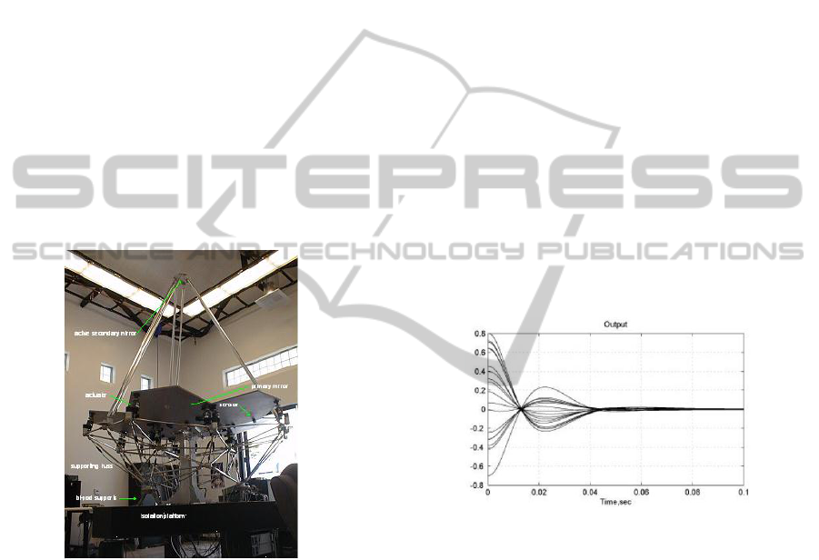
The SPACE testbed shown in Fig. 1 emulates a
Cassegrain telescope of 2.4-meter focal length with
performance comparable to an actual space-borne
system. The system's top-level requirements include
figure maintenance of the primary mirror to within 1
micron RMS distortion with respect to a nominal
shape of the primary mirror, and precision pointing
with accuracy of 2 arc seconds, (Boussalis et al.,
1996), (Boussalis, 2005), (Desai et al., 2011).
Figure 1: SPACE Testbed.
The SPACE testbed consists of a primary mirror,
a secondary mirror and a lightweight flexible truss
structure. The primary mirror (mounted on the
support truss) consists of seven hexagonal panels,
each 101 cm in diameter. The six peripheral panels
are actively controlled in the three degrees-of-
freedom by 18 linear electromagnetic actuators (3
actuators per active panel), and the seventh panel is
used as a reference. A set of 18 edge sensors are
used to provide measurements of relative
displacement and angle of the panels (3 sensors per
active panel). The Testbed’s active secondary mirror
is a six-sided pyramidal mirror used to reflect the
light from the primary mirror to the central plane
and is attached to the primary by a tripod. The entire
Testbed is supported by a triangular isolation
platform made of aluminum honeycomb core with
stainless steel top and bottom skin, (Morales, 2001).
2.1.1 Figure Maintenance
Unlike a monolithic primary mirror, a segmented
reflector, such as the JWST or the SPACE testbed,
requires an active control system to maintain the
desired optical performance. Active control of the
Testbed reflector panels was achieved using a set of
decentralized H-infinity controllers. Fig. 2 shows the
closed loop response results, (Morales et al., 1999),
using this control scheme under decentralized
control. It is anticipated that system model being
developed will allow the development of a new H-
infinity controller for pointing precision that can be
incorporated with the current figure maintenance
controller as a 7
th
local subcontroller to demonstrate
both figure maintenance and pointing precision
simultaneously.
It is evident that figure maintenance is achieved
using the decentralized control scheme described in
(Boussalis et al., 1996), (Boussalis, 2002), (Lim,
2011).
Figure 2: Closed loop response.
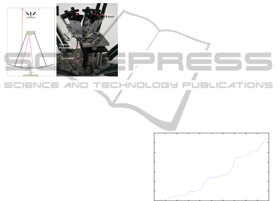
2.1.2 Peripheral Pointing Architecture
The SPACE telescope testbed is required to perform
precision pointing while maintaining the parabolic
shape of the primary mirror. In order to achieve
precision pointing of the Testbed with accuracy of 2
arc seconds, a Peripheral Pointing Architecture
(PPA) has been designed. The PPA structure is
shown in Fig. 3 (left).
The PPA uses an assembly of six lasers as shown
in Fig. 3 (right) to simulate the object of study. Each
laser corresponds to its own separate panel and
optical detector. The laser assembly sits on a
motorized tip/tilt platform and the laser source
coincides with the rotation, or gimbal, point of the
platform.
Since the laser source lies on the rotation point of
the platform, there is no translation or displacement
ICINCO 2012 - 9th International Conference on Informatics in Control, Automation and Robotics
596
of the source. When the motorized platform is tipped
or tilted, the source is stationary, while only the laser
beams direction are affected.
Using the distance from the platform’s rotation
point to each actuator, (a
x
and a
y
for the actuator on
each respective axis), and the actuator displacement,
it is calculated that the platform moves an angle θ
from its zero position on the y-axis. The platform’s
normal vector also moves the same angle θ from the
positive z-axis.
Figure 3: SPACE Testbed PPA Laser Path (left) and
physical assembly (right).
3 FINITE ELEMENT MODEL
DEVELOPMENT
3.1 SolidWorks Model
A geometric model of the PPA is developed using
SolidWorks. The PPA structure is composed of six
lasers, six laser holders, a hexagonal plate, the top
platform, the Newport 37 platform, two Newport
linear actuators, and nine supporting rods.
The PPA is composed of two main parts which
consist of a controllable and a fixed part. The
controllable part is the top half section of the
structure where the actuators push upwards in a
linear fashion and where the Newport 37 platform
has its gimbal point. For simplicity and ease of
computation the fixed part of the PPA structure was
removed. To develop the PPA model, first the model
for each component is developed. The designed
geometry is saved as a parasolid file and imported
into Finite Element Modeling and Post Processing
(FEMAP).
3.2 FEMAP Model
Subsequently, a mesh analysis is performed by
importing the SolidWorks model into FEMAP. The
analysis performed on the model resulted with
250000 nodes and 150000 elements. The minimum
number of nodes and elements achieved while
keeping reasonably accurate results using solid
elements is 146000 nodes and 91000 elements..
In using plate and beam elements, as opposed to
solid elements, the number of nodes and elements of
the model can are reduced significantly. Using plate
elements and increasing the growth ratio and mesh
density the model is reduced to 5795 nodes and 4993
elements.
The PPA model is constrained at three points.
Two points for the linear actuators are constrained in
the x-axis and y-axis for translation and in the x, y,
and z axes for rotation. The gimbal point has a
pinned constraint meaning that it is cannot translate.
4 RESULTS
An initial analysis shows the frequency range for the
first 100 modes ranged from 56.7 Hz to 13.017 kHz
as shown in Fig. 4. A second analysis yielded similar
results, but were truncated to the first 20 modes
(approximately 1 kHz), to reduce the size of the
eventual state-space model, since it was determined
that higher frequencies would not be within the
operational range.
0 10 20 30 40 50 60 70 80 90 100
0
2000
4000
6000
8000
10000
12000
14000
Mode #
Frequency (Hz)
Frequency vs 100 Modes
Figure 4: Frequency of first 100 modes of platform.
The first group of mode shapes corresponds to
deformations of the laser holders followed by the
deformation of the platform. The deformations of
mode 4 at 126.2326 Hz and mode 10 at 261.7744 Hz
are shown in Fig. 5. This figure shows the
deformations of the laser holders in the first group of
frequencies followed by the more rigid platform at
higher frequencies.
Mechanical Modeling of an Actuated Platform for Precision Pointing Control - Via Finite-element Analysis and Normal
Mode Analysis
597

(a) (b)
Figure 5: Mode 4, 126.23 Hz (a). Mode 10, 261.77 Hz (b).
5 CONTROL DESIGN
Consider the linear time-invariant system given by
the following state equations,
v
i
ii
uBAxx
1
NixCy
ii
,,1,
(1)
Where
n
x
,
i
m
i
u
and
i
p
i
y
represent
the state, input and output respectively of the ith
local control station. A, B
i
and C
i
are real, constant
matrices. The results of the modal analysis are used
to determine the matrices A, B
i
and C
i
that will
describe the dynamics of the PPA structure.
For decentralized control, it is necessary to
determine n local feedback control laws that will
dynamically compensate for (1) in order to stabilize
the control loop, generating the following feedback
controllers:
iiii
yGzFz
NivyKzHu
iiiiii
,,1,
(2)
where
i
n
i
z
and
i
m
i
v
are the ith
subcontroller and local external input and F
i
, G
i
, H
i
,
and K
i
are real, constant matrices. The standard two-
block mixed-sensitivity H-infinity technique,
(Morales et al., 1999), will be applied to accomplish
a pointing accuracy of 2 arc seconds to the final
reduced and validated state-space model.
6 CONCLUSIONS
An FEA model of an actuated laser platform used
for pointing control of a segmented telescope testbed
is developed. Modal analysis is performed on the
FEA model which calculates the natural frequencies,
mode shapes, degrees of freedom, and eigenvalues
of the structure. Further research is to be undertaken
to define which nodes are desirable and which nodes
are unnecessary in order to be able to perform
Guyan Reduction to reduce the size of the model for
practical implementation. The process described
here streamlines the process of modeling a
motorized platform from mechanical model (CAD,
SolidWorks, etc) to a preliminary, albeit enormous,
state-space model for the implementation of
controllers.
REFERENCES
H. S. Stockman, 1997. “The Next Generation Space
Telescope Visiting a Time When Galaxies Were
Young”.
H. Boussalis, Z. Wei, and M. Mirmirani, 1995. “Dynamic
Performance Modeling and Decentralization of A
Segmented Reflector Telescope,” IASTED Conference
on Modeling and Simulation, Mexico.
H. Boussalis, 1994. “Decentralization of Large
Spaceborne Telescopes”, Proc. 1994 SPIE Symposium
on Astronomical Telescopes, Hawaii.
H. Boussalis, M. Mirmirani, A. Chassiakos, K. Rad, 1996.
“The Use of Decentralized Control in Design of a
Large Segmented Space Reflector”, Control and
Structures Research Laboratory, California State
University, Los Angeles, Final Report.
H. Boussalis, 2002. “The Use of Decentralized Control in
Design of A Large Segmented Space Reflector”,
Structure Pointing and Control Laboratory, California
State University, Los Angeles, Final Technical Report.
H. Boussalis, K. Rad, A. Khosafian, Y. Komandyan, 2005.
“Pointing Control Testbed for Segmented Reflectors”.
A. Desai, J. Alvarenga, H. Tarsaria, K. Rad, H. Boussalis,
2011. “Ray Tracing Visualization Using LabVIEW
for Precision Pointing Architecture of a Segmented
Reflector Testbed,” MED 2011, Corfu, Greece.
M. J. Morales, 2001. “Design and modeling of the SPACE
Tesbted,” M.S. Thesis, Department of Electrical
Engineering, California State University, Los Angeles,
Los Angeles, CA, USA.
M.J. Morales, M. Mirmirani, H. Boussalis, 1999. “Design,
Simulation & Control of a Segmented Reflector Test-
bed,” MED 1999, Haifa, Israel.
K. Lim, 2011. “Modelling and Overlapping Decentralized
Control of a Large Segmented Telescope Test-Bed,”
PhD Dissertation, University of Southern California,
Los Angeles, CA, USA.
K. J. Bathe, and E. L. Wilson, 1976. Numerical Methods
in Finite Element Analysis, 2nd Ed., John Wiley and
Sons.
C. H. Ih, H. C. Briggs, S. J. Wang, 1990. “3D Dynamic
Modeling and Simulation of a Precision Segmented
Reflector Telescope”, Proceedings of the 21st Annual
Pittsburgh Conference.
H. Ryaciotaki-Boussalis, H. C. Briggs, and C. H. Ih, 1991.
“Dynamic Performance Modeling and Stability
Analysis of a Segmented Reflector Telescope,”
Proceedings of the 1991 Automatic Control
Conference.
ICINCO 2012 - 9th International Conference on Informatics in Control, Automation and Robotics
598

A. C. Carrier, 1990. “Modeling and Shape control of a
Segmented-Mirror Telescope,” Ph.D. dissertation,
Dept. Aeronautics and Astronautics, Stanford Univ.,
Stanford, CA.
R. D. Cook, 1981. Concepts and Applications in Finite
Element Analysis, 2nd Ed., John Wiley and Sons.
R. Bishop, and D. C. Johnson, 1981. The Mechanics of
Vibration, Cambridge University Press.
Mechanical Modeling of an Actuated Platform for Precision Pointing Control - Via Finite-element Analysis and Normal
Mode Analysis
599
