
Observer-based Adaptive Sliding Mode Control for a Pneumatic
Servo System
Kuo-Ming Chang
1
and Tien-Tsai Kung
2
1
Department of Mechanical Engineering, National Kaohsiung University of Applied Sciences,
415 Chien-Kung Rd., Kaohsiung, Taiwan
2
Institute of Mechanical and Precision Engineering, National Kaohsiung University of Applied Sciences,
415 Chien-Kung Rd., Kaohsiung, Taiwan
Keywords: Pneumatic Servo System, Adaptive Sliding Mode Control, Extended State Observer, Dead-Zone.
Abstract: This paper combines an extended state observer (ESO) and adaptive sliding mode control to deal with the
problem of nonlinear input dead-zone, unkonw system function, external distrubance and system states
unmeasured in a pneumatic servo system. Firstly, an extended state observer is applied to estimate system
state variables and uknown system nonlinear function contained the external disturbance, and an adaptive
law is used to estimate unknown dead-zone parameters. Then, an observer-based adaptive sliding mode
control can be derived for such a uncertain pneumatic servo system. Furturemore, the proposed control
scheme in this paper is applied to a pneumatic positioning control experimental equipment and it is shown
that the positioning accuracy with less than 0.05
m
can be obtained.
1 INTRODUCTION
In recent year, pneumatic servo system has been
widely used in automation industry with low cost,
fast, and long stroke, but owing to the
compressibility of air, the friction force of the
contact surface, and the nonlinear input dead-zone of
servo valve, the pneumatic servo system can not
reach high precision positioning accuracy. In order
to improve the positioning performance of
pneumatic servo system, many control methods have
been proposed, such as sliding mode control (Song
and Ishida, 1997; Korondi and Gyeviki, 2006),
neural network control (Gross and Rattan, 1998),
fuzzy PWM control (Shih and Ma, 1998) and the
control scheme of the pneumatic system combined
with piezoelectric actuator (Liu et al., 2004; Chiang
et al., 2005).
In this paper, based on the extended state
observer, sliding mode control, and adaptive dead-
zone inverse techniques, a robust observer-based
adaptive sliding mode control scheme is developed
to achieve the high positioning performance for a
pneumatic servo positioning system. Furthermore, it
is proven that the proposed control scheme can
obtain the positioning accuracy with less than
0.05
m
in an experimental pneumatic servo control
system.
2 PNEUMATIC SERVO SYSTEM
In this paper, the dynamic equation of pneumatic
system can be constructed as:
applied
F
dt
dx
η
dt
xd
m
1
2
1
2
(1)
where
m
: mass of sliding table
: damping coefficient
applied
F
: force of pneumatic cylinder
)(
1
tx
: displacement of sliding table
Eq. (1) is a second-order linear differential
equation, but owing to characteristics of air
compression and nonlinear friction, it will be
difficult to represent the pneumatic servo system
with a linear system actually. Therefore, considering
the nonlinear characteristics of pneumatic system,
Eq. (1) can be rewritten by
m
F
td
m
xxfxf
dt
xd
appliedPf
)(
),()(
111
2
1
2
(2)
600
Chang K. and Kung T..
Observer-based Adaptive Sliding Mode Control for a Pneumatic Servo System.
DOI: 10.5220/0004032806000604
In Proceedings of the 9th International Conference on Informatics in Control, Automation and Robotics (ICINCO-2012), pages 600-604
ISBN: 978-989-8565-21-1
Copyright
c
2012 SCITEPRESS (Science and Technology Publications, Lda.)

where
)(
1
xf
f
: nonlinear function of friction
),(
11
xxf
P
: nonlinear function of air compression
)(td
: external disturbance and system unmodeled
error.
In a pneumatic servo system, the nonlinear dead-
zone phenomenon is usually caused by proportional
valve and nonlinear friction. Concerning about the
dead-zone phenomenon, Eq. (2) can be further
rewritten in the state-space representation
)()()()(),(
2
21
tauwtgtdtxfx
xx
(3)
where
T
21
])( )([)( tx txtx
is the system state vector,
m
xxfxf
txf
Pf
),()(
),(
111
is the unknown system
nonlinear function,
)(tg
is the unknown control
gain,
)(tu
is the control input,
)(uw
is the output
of unknown dead-zone expressed as
lll
rl
rrr
bubtum
bub
bubtum
uw
if,))((
if, 0
if,))((
)(
(4)
where
0
l
m
and
0
r
m
are the slopes of dead-zone
on both sides,
0
l
b
and
0
r
b
are the breaking
points of dead-zone on both sides. In addition,
regarding to
)(td
and
)(ta
of in Eq. (3) and
parameters in Eq. (4), this paper has the following
assumptions:
Assumption 1: External disturbance of system is a
bounded function, such as
|)(| td
,
is positive
constant.
Assumption 2:
)(ta
is continuously differentiable
with time and its time derivative is bounded.
Assumption 3:
r
m
,
l
m
,
r
b
, and
l
b
are four
unknown positive constants, which are bounded by
maxmin r rr
mmm
,
maxmin l ll
mmm
,
maxmin r rr
bbb
, and
maxmin l ll
bbb
.
3 OBSERVER-BASED ADAPTIVE
SLIDING MODE CONTROL
Owing to pneumatic servo system is a nonlinear and
time-varying system, traditional control methods are
usually difficult to achieve a better positioning
performance. Among the modern controls, the
sliding mode control is less dependent on exact
mathematical model of system and has a good
robustness with respect to system uncertainty. For
designing the sliding mode control, a sliding surface
constituted with stage displacement and its
derivative with respect to time is firstly constructed,
but the derivative of displacement is not easy to
measure. Therefore, in this paper, extended state
observer will be applied to estimate displacement
derivative and system uncertainty. Then, an
observer-based adaptive sliding mode control
techniques is developed to achieve a high
positioning performance for a pneumatic servo
system.
3.1 Extended State Observer
Eq. (3) shows that system state variables are
1
x
and
2
x
. Let us expand
13
xx
as another system state.
Then, we have
)(
)(
3
32
21
tax
taxx
xx
(5)
Follows the work (Han, 1995), the structure of ESO
is given as
)
ˆ
(
ˆ
)
ˆ
(
ˆˆ
)
ˆ
(
ˆˆ
1133
11232
11121
xxkx
xxkxx
xxkxx
(6)
Define the estimated state errors as
)(-
ˆ
-
ˆ
Δ
-
ˆ
Δ
-
ˆ
Δ
3333
222
111
taxxxx
xxx
xxx
(7)
Then, from Eq. (7), we can obtain the dynamic
equation of estimated state error in the following
form:
)(
0
0
Δ
Δ
Δ
00
10
01
Δ
Δ
Δ
3
2
1
3
2
1
3
2
1
tax
x
x
k
k
k
x
x
x
(8)
Parameters
1
k
,
2
k
, and
3
k
are chosen such that
the dynamical system in Eq. (8) is asymptotic stable.
3.2 Observer-based Adaptive Sliding
Mode Control
For designing a sliding mode control, the first step is
to construct a sliding surface. The sliding surface is
Observer-based Adaptive Sliding Mode Control for a Pneumatic Servo System
601

set as
)(
112 d
xxcxs
(9)
where
1
c
is a positive constant and
d
x
is a desired
reference signal. Then, we have
)(
112 d
xxcxs
)Δ
ˆ
()Δ
ˆ
(
11122 d
xxxcxx
112112
ΔΔ)
ˆ
(
ˆ
xcxxxcx
d
(10)
where
1112
ΔΔ
xcx
,
0
1
.
Define an almost sliding surface
s
ˆ
as
)
ˆ
(
ˆˆ
112 d
xxcxs
(11)
From Eq. (11), Eq. (10) can be expressed as
112
ΔΔ
ˆ
xcxss
(12)
From Eq. (12), we can obtain
1
ˆ
ss
(13)
Differentiating
s
ˆ
with respect to time, we have
11012
ˆ
Δ
ˆ
xcwgdfxs
(14)
where
wggwdd
01
.
From Eq. (14), let
0
ˆ
s
and
0Δ
2
x
, an equivalent
nonlinear control input can be obtained as
0
111
ˆ
)(
g
xcdf
w
eq
(15)
In addition to the equivalent nonlinear control input,
a nonlinear switching control input is given as
)
ˆ
(
ˆ
s
satkskw
ds
(16)
where
is a sufficiently small positive constant,
d
k
and
k
are two positive constants which must satisfy
the condition
kk
d
2
,
0
2
.
From Eqs. (7) and (16), nonliner control input
d
w
can be obtained as
seqd
www
)
ˆ
(
ˆ
ˆ
)(
0
111
s
ksatsk
g
xcdf
d
(17)
Considering Eqs. (3) and (10),
)(
1
df
can be repla
ced by
wgx
02
ˆ
and then
w
is replaced by a filter
signal
d
w
ˆ
given from the following equation
ddd
www
ˆˆ
where
is a positive constant and the filter can let
d
w
ˆ
have the property,
ww
d
t
ˆ
limlim
.
Therefore, Eq. (17) can be rewritten as
)
ˆ
(
ˆ
ˆˆˆ
0
1102
s
ksatsk
g
xcwgx
w
d
d
d
(18)
Because function
w
and dead-zone parameters are
unknown, the control input is given by
d
l
lld
d
d
r
rrd
ee
m
bmw
ee
ee
m
bmw
u
1
1
1
if,
ˆ
||if, 0
if,
ˆ
(19)
Define parameter vectors as
lr
nnN
(20)
T
lr
mmM
(21)
T
llrr
bmbm
(22)
With
otherwise, 0
if,1
1 d
r
ee
n
(23)
otherwise,0
if,1
1 d
l
ee
n
(24)
It follows that estimated paramter vectors as
T
ˆˆ
ˆ
lr
mmM
(25)
T
T
]
ˆˆ
[
ˆ
llrrlr
bmbm
(26)
and the paramter error vector as
ˆ
~
(27)
Define the dead-zone and the estimated dead-zone
slope ratios as
T
T
T
11
l
l
r
r
lr
m
m
m
m
(28)
and
T
T
ˆˆ
ˆˆˆ
l
l
r
r
lr
m
m
m
m
(29)
Define
ˆ
~
(30)
Finally, the control input can be designed in the
︿
︿
︿
︿
ICINCO 2012 - 9th International Conference on Informatics in Control, Automation and Robotics
602
following form
)
ˆ
(
ˆ
1
Nw
MN
u
d
(31)
ˆ
can be obtained from the following adaptive law
T
ˆ
Ns
(32)
where
)
ˆ
(
ˆ
s
satss
and
is a positive constant.
M
ˆ
can be obtained from the following equations
njnjnj
mm
,,1,
ˆ
ˆ
ˆ
(33)
T
ˆ
Ns
(34)
where
ˆ
Nw
d
and
is a positive constant.
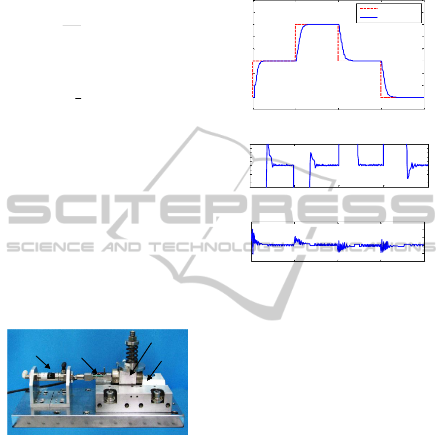
3 EXPERIMENTAL RESULTS
To illustrate and validate the positioning control
performance, the proposed control scheme is applied
in a pneumatic servo sytem shown in Fig. 1. Fig. 2
illustrates the positioning control experimental
results of pneumatic servo system. From Fig 2 (b), it
is shown that the positioning error is less than
0.05
m
when sliding table moves forward or
backward.
Pneumatic cylinder
PZT
Sliding table
V groove
Figure 1: Photograph of the experimental equipment.
4 CONCLUSIONS
In this paper, an observer-based adaptive sliding
mode control is developed for a pneumatic servo
control system with nonlinear dead-zone and system
uncertainty according to extended state observer,
sliding mode control, and adaptive dead-zone
inverse techniques. The proposed control scheme is
also applied to a pneumatic positioning control
experiment and from experimental results, it is
shown that the positioning accuracy with less than
0.05 can be obtained.
0 5 10 15 20
-1
0
1
2
3
4
5
6
7
8
Time (s)
Displacement (mm)
Reference Input
(a) Displacement
0 5 10 15 20
-0.5
-0.4
-0.3
-0.2
-0.1
0
0.1
0.2
0.3
0.4
0.5
Time (s)
Error (
m)
(b) Displacement error
0 5 10 15 20
4.5
4.6
4.7
4.8
4.9
5
Time (s)
Voltage (V)
(c) Control voltage
Figure 2: Pneumatic positioning control.
ACKNOWLEDGEMENTS
The authors would like to acknowledge the support
from National Science Council, Taiwan, Republic of
China for this work, under Grant NSC 100-2221-E-
151-006.
REFERENCES
Chiang, M. H., Chen, C. C., Tsou, T. N., 2005. Large
Stroke and High Precision Pneumatic-Piezoelectric
Hybrid Positioning Control Using Adaptive Discrete
Variable Structure Control. Mechatronics, Vol. 15, pp.
523-545.
Gross, D. C, Rattan, K. S., 1998. An Adaptive Multilayer
Neural Network for Trajectory Tracking Control of A
Pneumatic Cylinder. Proceedings of IEEE
International Conference on Systems, Man, and
Cybernetics, Vol. 2, pp. 1662–1667.
Han, J., 1995. Extended State Observer for A Class of
Uncertain Plants. Control Decis., Vol. 10, No. 1, pp
85-88.
Korondi, P., Gyeviki, J., 2006. Robust Position Control for
a Pneumatic Cylinder. 12
th
Power Electronics and
Motion Control Conference, pp. 513-518.
1
x
Observer-based Adaptive Sliding Mode Control for a Pneumatic Servo System
603

Liu, Y. T., Lee, C. H., Fung, R. F., 2004. A Pneumatic
Positioning Device Coupled with Piezoelectric Self-
Moving Mechanism. Asian Journal of Control, Vol. 6,
No. 2, pp. 199-207, 2004.
Shih, M. C., Ma, M. A., 1998. Position Control of A
Pneumatic Cylinder Using Fuzzy PWM Control
Method. Journal of Mechatronics, Vol. 8, No. 3, pp.
241-253.
Song, J., Ishida, Y., 1997. A Roboust Sliding Mode
Control for Pneumatic Servo Systems. International
Journal of Engineering Science, Vol. 35, No. 8, pp.
711-723.
ICINCO 2012 - 9th International Conference on Informatics in Control, Automation and Robotics
604
