
Wave Vibration Analysis of Classical Multi-story Planar Frames
C. Mei
Department of Mechanical Engineering, The University of Michigan - Dearborn,
4901 Evergreen Road, Dearborn, MI 48128, U.S.A.
Keywords: Wave Vibration, Multi-story Frame, Bending Vibration, Longitudinal Vibration.
Abstract: This paper concerns free vibration analysis of in-plane vibrations in classical multi-story planar frame
structures. An exact analytical solution is obtained using wave vibration approach. The coupling effects
between bending and longitudinal vibrations in frames are taken into account. Classical beam theories are
applied in modeling the flexural and longitudinal vibrations. Reflection matrices at “sliding” and “rolling”
boundaries, as well as reflection and transmission matrices at the “L” and “T” joints are obtained.
Numerical examples are presented along with comparisons to results available in literature.
1 INTRODUCTION
Due to their complexity, vibrations in multi-story
planar frame structures are often analyzed either
based on approximated discrete models such as
lumped mass/elasticity models, or using numerical
approach such as the Finite Element Analysis (FEA)
approach. There are very limited analytical studies
based on distributed models found in the literature.
Lumped mass/elasticity may be suitable for
finding the fundamental frequency of a multi-story
frame, but they are prone to large errors and are
therefore not suitable for identifying higher modes
of vibration. The FEA approach is usually applied in
modeling multi-story frames (Vertes, 1985, and
Meirovitch, 2001), its accuracy is dependent upon
the number of meshes or nodes per structural
element. In general, higher modes demand more
nodes, consequently the FEA approach is only
suitable for relatively low frequencies. A branch
mode method was developed for studying in-plane
vibrations in multi-story frames (Gladwell, 1964)
with longitudinal vibrations neglected in the
analysis.
In this paper, vibrations in multi-story planar
frame structures are obtained analytically from wave
vibration standpoint (Graff, 1975; Cremer et. al.,
1987, and Doyle, 1989). Reflection matrices at
“sliding” and “rolling” boundaries, as well as
reflection and transmission matrices at the “L” and
“T” joints are discussed. The coupling effects of
flexural and longitudinal motions at joints are taken
into account. This study is based on the classical
vibration theories, as a result, it is suitable to
relatively low frequencies.
2 EQUATION OF MOTION AND
WAVE PROPAGATION
Consider the forces and moments acting on a
uniform element of a beam lying along the x-axis.
When applying classical beam/rod related theories,
the equations of motion for bending and longitudinal
vibrations are (Inman, 1994; and Ginsberg, 2001)
),(
),(),(
2
2
4
4
txq
t
txy
A
x
txy
EI
,
(1a)
),(
),(),(
2
2
2
2
txp
x
txu
EA
t
txu
A
,
(1b)
where x is the position along the beam axis, t is time,
),( txy
and
),( txu
are the transverse and
longitudinal deflections of the centerline of the
beam;
),( txq
and
),( txp
are the externally applied
transverse and longitudinal forces; E and
are the
Young’s modulus and mass density; respectively. I
is the area moment of inertia of cross section, A is
the cross-sectional area.
The shear force
),( txV
, bending moment
),( txM
, and longitudinal force
),( txF
at any
section of the beam are related to the transverse
488
Mei C..
Wave Vibration Analysis of Classical Multi-story Planar Frames.
DOI: 10.5220/0004035204880493
In Proceedings of the 9th International Conference on Informatics in Control, Automation and Robotics (ICINCO-2012), pages 488-493
ISBN: 978-989-8565-21-1
Copyright
c
2012 SCITEPRESS (Science and Technology Publications, Lda.)

deflection
),( txy
, bending slope
),( tx
, and
longitudinal deflection
),( txu
by
,
),(
3
3
x
txy
EIV
,
),(
x
tx
EIM
,
),(
x
txu
EAF
(2)
where
x
txy
),(
according to the classical Euler-
Bernoulli beam theory.
2.1 Free Wave Propagation
First, consider the free bending vibration problem
when no external force is applied to the beam.
Assuming time harmonic motion and using
separation of variables, the solution to Eq. (1a) can
be written in the form
tiikx
eeytxy
0
),(
, where
is frequency and k is the wavenumber. A set of
bending wavenumbers is found as
EIAk
22
.
(3)
Now consider the free longitudinal vibration
problem when no external force is applied to the
beam. Again assuming time harmonic motion and
using separation of variables, the solution to Eq. (1b)
can be written in the form
.),(
0
tiikx
eeutxu
The longitudinal wavenumber is found as
Ek
.
(4)
2.2 Propagation Matrix
Consider two points A and B on a uniform beam a
distance x apart. Waves propagate from one point to
the other, with the propagation being determined by
the appropriate wavenumber. Denoting the positive
and negative going wave vectors at points A and B
as
a
and
a
and
b
and
b
, respectively, they are
related by
bfa )(x
;
afb )(x
(5)
where
)(xf
is the propagation matrix for a distance
x.
3 REFLECTION AND
TRANSMISSION OF COUPLED
BENDING AND
LONGITUDINAL WAVES
Waves incident upon discontinuities (such as
boundaries and joints) are reflected and transmitted.
In this section, reflection matrices at “sliding” and
“rolling” boundaries, and reflection and transmission
matrices at “L” and “T” joints are studied.
3.1 Wave Reflection at Boundaries
An incident wave is reflected at a boundary, as
shown in Figure 1. The incident wave
a
and the
reflected wave
a
are related through the reflection
matrix
r
by
raa
,
(6)
where r can be determined by considering
equilibrium at the boundary.
For “sliding” boundary, the equilibrium
conditions at the boundary are
0
,
,0),( txV
.0),( txu
(7)
The equilibrium conditions at a “rolling” boundary
are
,0),( txy
,0),( txM
.0),( txF
(8)
The reflection matrices at classical boundaries such
as clamped and free boundaries are derived in (Mei,
2010).
3.2 Wave Reflection and Transmission
at an “L” Joint
Wave transmission and reflection at an angle joint in
general introduce wave mode conversion. At an “L”
joint, for example, an incident bending wave induces
reflected and transmitted bending and axial waves in
the members attached to the joint. This is evident
from the coupled equilibrium and continuity
relations below.
Figure 2 shows the free body diagram of an “L”
joint in planar motion. The equilibrium conditions
are
J
ymVF
..
12
(9)
J
umFV
..
12
J
J
h
V
h
VMM
..
1
2
2
112
22
where F is the axial force in the beam and h the
beam thickness. Subscripts 1 and 2 refer to beam 1
and beam 2,
J
u
,
J
y
, and
J
are the displacements
and rotation of the joint as indicated in the figure.
The first two of these equations include the mass of
the joint, while the third includes the moment of
inertia of the joint and the moments induced by the
off-set shear forces.
Wave Vibration Analysis of Classical Multi-story Planar Frames
489

Figure 1: Sliding (a) and rolling (b) boundaries.
The continuity equations at the joint are
J
uu
1
,
J
yu
2
,
JJ
h
yy
2
2
1
,
JJ
h
uy
2
1
2
,
J
1
,
J
2
(10)
A set of positive going waves
a
incident upon the
L-joint from one beam gives rise to transmitted and
reflected waves
b
and
b
, which are related to the
incident waves through the transmission and
reflection matrices t and r by
Tab
,
Raa
.
(11)
The transmission and reflection matrices
12
T
and
11
R
corresponding to an incident wave from beam 1
and the transmission and reflection matrices
21
T
and
22
R
corresponding to an incident wave from Beam 2
can be obtained from solving Eqs. (9) to (11).
3.2 Wave Reflection and Transmission
at a “T” Joint
Similarly, wave transmission and reflection at a “T”
joint also introduce wave mode conversion. The
transmission and reflection matrices are obtained
from considering the continuity and equilibrium
conditions at the joint. The free body diagram of a
“T” joint in planar motion is shown in Figure 3. The
continuity equations at the joint are
,
1 J
uu
,
2 J
yu
,
3 J
uu
,2
21
hyy
JJ
,2
12
huy
JJ
,2
33
hyy
JJ
,
1 J
,
2 J
.
3 J
(12)
The equilibrium conditions are
,
..
123
J
ymVFV
,
..
123
J
umFVF
(13)
.
222
..
1
2
2
1
2
3123
J
J
h
V
h
V
h
VMMM
There exist three sets of reflection and trans- mission
relations, corresponding to incident waves from each
of the three beam elements respectively. The
reflection and transmission relations can be found
from Eqs. (12) and (13). More details can be found
in (Mei, 2010).
4 WAVE VIBRATION ANALYSIS
OF A MULTISTORY FRAME
For a multi-story frame that is symmetrical about a
vertical line through the centers of the spans, the
vibration modes are either symmetrical or anti-
symmetrical. It has been shown that vibrating in
symmetrical modes, the mid-points of the cross-
members behave as sliding ends; while vibrating in
anti-symmetrical modes, the mid-points of the cross-
members behave as rolling ends (pinned vertically
but allowing translational motion in the horizontal
direction). As a result, when the frame is vibrating in
a symmetrical mode, each half of it will have the
same modal form as the isolated half frame shown in
Figure 4(a); and when it is vibrating in one of its
anti-symmetrical modes, each half of it can be
treated as if it is an isolated half-frame having the
form shown in Figure 4(b) (Gladwell, 1964, and
Bishop and Johnsona, 1960).
4.1 Free Wave Vibration Analysis
From wave vibration standpoint, vibrations
propagate along a uniform waveguide (or structural
element), and are reflected and transmitted at
discontinuities (such as joints and boundaries).
Assembling these propagation, reflection, and
transmission matrices offers a concise and
systematic approach for analyzing coupled bending
and longitudinal vibrations in a multi-story frame
structure.
Figure 4(a) illustrates an n-story frame vibrating
at its symmetrical modes. The half frame model
consists of n horizontal and n vertical beam
elements. And the discontinuities in the half frame
model include one “L” joint, (n-1) “T” joints, one
classical boundary, and n sliding boundaries.
The n pairs of propagation relations along the
uniform vertical beam elements are
1
)(
ii
L Afa
,
ii
L afA )(
1
,
(14a)
where i = 1, 2, ..., n.
ICINCO 2012 - 9th International Conference on Informatics in Control, Automation and Robotics
490

Figure 2: Free body diagram of an “L” joint.
The n pairs of propagation relations along the
uniform horizontal beam elements are
LiHRi
L cfc )2(
,
RiHLi
L cfc )2(
,
(14b)
where i = 1, 2, ..., n.
The reflection and transmission relations of the
waves at “T” joints are
Liiii
ctAtara
213111
,
Liiii
ctatArA
231333
,
13221222
Atatcrc
LiLi
,
(15c)
where i = 1, 2, ..., n-1.
The reflection and transmission relations of the
waves at “L” joint are
nLnLn
aTcRc
1222
,
.
2111
Lnnn
cTaRa
(15d)
The reflection relations at the sliding boundaries
are
RislidingRi
crc
,
(15e)
where i = 1, 2, ..., n.
The reflection at the classical boundary is
.
000
ArA
(15f)
Writing Eqs. (13) in matrix form gives
0Az
,
(16)
where A is a (24n) by (24n) coefficient matrix and z
is a 24n wave component vector. Setting the
determinant of the coefficient matrix A to zero gives
the natural frequencies of the multi-story frame.
Figure 4(b) illustrates an n-story frame vibrating
at its anti-symmetrical modes. The analysis follows
Figure 3: Free body diagram of a “T” joint.
a similar procedure, the only difference is that the n
sliding boundaries are replaced by n rolling
boundaries.
4.2 Numerical Examples
Two example multi-story frame structures are
studied, one being a three-story frame and the other
a two-story frame. For comparison purpose, the
physical properties of the three-story frame are
chosen to be the same as those in (Vertes, 1985) and
they are as follows: Lengths of vertical and
horizontal beams are 6.0m and 8.0m respectively,
cross sectional area
2
3.0 mA
, area moment of
inertia
4
01.0 mI
, Young’s modulus
2
210 mGNE
,
and mass density
3
25 mkN
. The physical
properties of the two-story frame are chosen to be
the same as those in (Petyt, 1990) and they are as
follows: Lengths of vertical and horizontal beams
are 22.86cm and 45.72cm respectively, the cross
section of the beam elements is 0.3175cm by
1.27cm, Young’s modulus E is
2
84.206 mGN
, and
mass density
is
3
7830 mkg
. The boundary
conditions are clamped-clamped.
The natural frequencies of the two example
frames are listed in Tables 1 and 2, with
comparisons to the related references respectively.
The examples show good agreement with the results
presented in the available literature.
5 CONCLUSIONS
In this paper, in-plane vibrations in multi-story
planar frames are analyzed using the wave approach.
The vibrations are modeled using classical vibration
theories. The coupling effect between bending and
Wave Vibration Analysis of Classical Multi-story Planar Frames
491
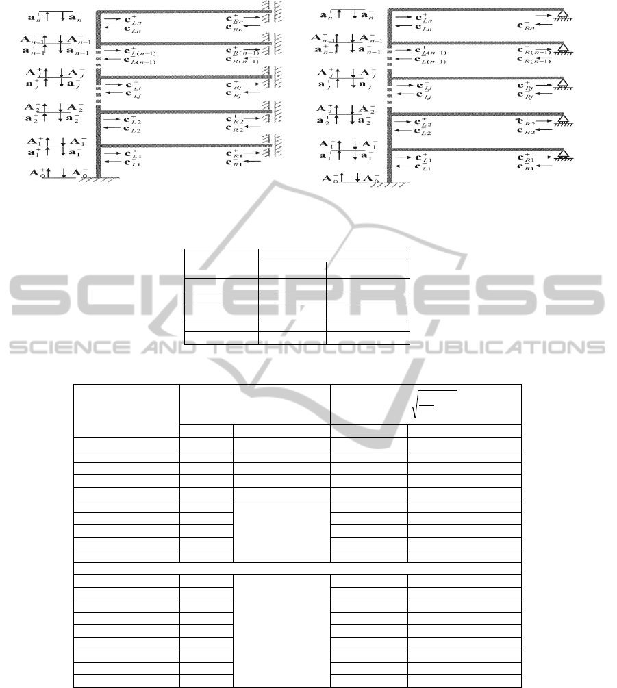
Figure 4: Half frames for symmetrical (a), and anti-symmetrical (b) mode analysis.
Table 1: Natural frequencies of the 3-story frame. (superscript a denotes anti-symmetrical modes).
Modes
Natural frequencies (rad/s)
Present
(Vertes,1985)
1
11.7
a
11.7
2
39.4
a
39.4
3
73.1
a
73.2
4
104.0
N/A
5
121.8
121.0
Table 2: Natural frequencies of the 2-story frame.
Modes
Natural frequencies (Hz)
2
4
2
L
EI
A
Present
(Petyt, 1990)
Present
(Gladwell, 1964)
Anti-symmetrical
15.1421
15.14
1.0554
1.0554
53.3183
53.32
3.7164
3.7165
155.3018
155.48
10.8248
10.8262
186.1038
186.51
12.9717
12.9819
270.0581
270.85
18.8235
18.8256
345.8450
N/A
24.1060
24.1133
590.5131
41.1597
41.2266
652.7439
45.4973
45.5200
794.7385
55.3946
55.4848
905.8716
63.1407
N/A
Symmetrical
56.1226
N/A
3.9118
3.9124
67.2203
4.6854
4.6866
212.5325
14.8139
14.8186
291.5674
20.3227
20.3441
381.6300
26.6002
26.6516
410.3624
28.6029
28.6143
699.3279
48.7443
48.7989
834.6623
58.1773
58.3556
986.1119
68.7336
68.9144
longitudinal vibrations is taken into account.
Reflection matrices at “sliding” and “rolling”
boundaries, as well as reflection and transmission
matrices at the “L” and “T” joints are discussed.
With the availability of the propagation, reflection,
and transmission matrices, vibration analysis of
multi-story planar frames becomes systematic and
concise: it involves a simple assembly of the
involved matrices. The procedures are illustrated
using two numerical examples, both show good
agreement with the results presented in the available
literature.
ACKNOWLEDGEMENTS
The author gratefully acknowledges the support on
ICINCO 2012 - 9th International Conference on Informatics in Control, Automation and Robotics
492

this project from the CMMI Division of the NSF
through Grant #0825761.
REFERENCES
Bishop R. E. D. and Johnson D. C., 1960, The Mechanics
of Vibration, Cambridge University Press, Great
Britain.
Cremer L., Heckl M. and Ungar E. E., 1987, Structure-
Borne Sound, Berlin: Springer-Verlag.
Doyle J. F., 1989, Wave Propagation in Structures, New
York: Spring – Verlag.
Ginsberg J. H., 2001, Mechanical and Structural
Vibrations, New York: John Wiley and Sons, Inc.
Gladwell G. M. L., 1964, “The Vibration of Frames,”
Journal of Sound and Vibration, 4, pp. 402-465.
Graff K. F., 1975, Wave Motion in Elastic Solids, Ohio
State University Press.
Inman D. J., 1994, Engineering Vibrations, New Jersey:
Prentice-Hall, Inc.
Mei C., 2010, “In-plane vibrations of classical planar
frame structures – an exact wave-based analytical
solution,” Journal of Vibration and Control, 16(9), pp.
1265-1285.
Meirovitch L., 2001, Fundamentals of Vibrations,
McGraw Hill, New York.
Petyt M., 1990, Introduction to Finite Element Vibration
Analysis, Cambridge University Press, Great Britain.
Vertes G., 1985, Structural Dynamics, Elsevier Science
Publishers B.V., The Netherlands.
Wave Vibration Analysis of Classical Multi-story Planar Frames
493
