
Parametric Study of Complex Liquid Flow in a Centrifugal Pump
Consisting of an Impeller, a Volute and a Diffuser
Guyh Dituba Ngoma, Walid Ghie, Nicolas La Roche-Carrier
University of Quebec in Abitibi-Témiscamingue, School of Engineering’s Department, 445, Boulevard de l’Université,
Rouyn-Noranda, Quebec, J9X 5E4, Canada
Keywords: Centrifugal Pump, Impeller, Volute, Diffuser, Turbulence, CFD, Modeling and Simulation.
Abstract: In this work, the numerical investigation of the complex liquid flow in a centrifugal pump modelconsisting
of an impeller, a diffuser and a volute was done to analyze the effects that the blade height, the diffuser
blade number, and the volute size had on the pump performance. The continuity and Navier-Stokes
equations with the k-ε turbulence model and the standard wall functions based on the logarithmic law were
used by mean of ANSYS-CFX code. The results achieved reveal that the selected key design parameters
have an impact on the pump head, the brake horsepower and the overall efficiency.
1 INTRODUCTION
Centrifugal pumps are widely used in industrial and
mining enterprises. One of the most important
components of a centrifugal pump is the impeller
(Peng, 2008). The performance characteristics
related to the pump comprising the head, the brake
horsepower and the overall efficiency rely a great
deal on the impeller. To achieve better performance
for a centrifugal pump, design parameters must be
accurately determined, due to the complex liquid
flow through a centrifugal pump. It is therefore
important to be aware of the liquid flow’s behavior
when passing through an impeller. This can be done
by accounting for the impeller, the diffuser and the
volute in the planning, design, and optimization
phases at conditions of design and off-design. Many
experimental and numerical studies have been
carried out on the liquid flow through a centrifugal
pump (Cheah et al., 2007; Djerroud et al., 2011;
Ozturk A. et al., 2009). The analysis of previous
works clearly demonstrated that research results
obtained are specific to the centrifugal pump design
parameter values and thus cannot be generalized. In
this work therefore a numerical study was performed
using a finite volume method according to the CFX
code (Ansys inc., 2008) to gain further insight into
the characteristics of the turbulent liquid flow
through a centrifugal pump consisting of an
impeller, a diffuser and a volute, while also
considering various flow conditions and pump
design parameters: blade height, blade number, and
volute size.
2 GOVERNING EQUATIONS
Fig. 1 shows the fluid domain of the considered
centrifugal pump model.
Figure 2: Centrifugal pump fluid domain.
The theoretical analysis of the liquid (water)
flow in the considered centrifugal pump model was
based on the continuity and Navier-Stokes equations
(Ansys inc., 2008). Thus, the continuity equations
are expressed by:
0U. =∇
r
,
(1)
and the Navier–Stokes equations are given by:
B))U(U.(p)UU.(
T
eff
+∇+∇∇μ+−∇=⊗∇ρ
r
r
r
r
(2)
where
(
)
(
)
(
)
(
)
z,y,xw,z,y,xv,z,y,xuUU
r
r
= is the liquid flow
Volute
Diffuser
Impeller
343
Dituba Ngoma G., Ghie W. and La Roche-Carrier N..
Parametric Study of Complex Liquid Flow in a Centrifugal Pump Consisting of an Impeller, a Volute and a Diffuser.
DOI: 10.5220/0004035503430346
In Proceedings of the 2nd International Conference on Simulation and Modeling Methodologies, Technologies and Applications (SIMULTECH-2012),
pages 343-346
ISBN: 978-989-8565-20-4
Copyright
c
2012 SCITEPRESS (Science and Technology Publications, Lda.)
velocity vector, p is the pressure, ρ is the density
(997 kg/m³), μ
eff
is the effective viscosity accounting
for turbulence, ⊗ is a tensor product and B is the
source term. More particularly, for flows in an
impeller rotating at a constant speed ω, the source
term can be written as follows:
()
(
)
rxxUx2B
r
r
r
r
r
ωω+ωρ−=
(3)
where
r
r
is the location vector.
In addition, μ
eff
is defined as:
teff
μ+μ=μ
(4)
where μ is the dynamic viscosity (8.899 x 10
-4
Pas)
and μ
t
is the turbulence viscosity (Ansys inc., 2008).
The actual pump head rise is given by:
⎟
⎟
⎠
⎞
⎜
⎜
⎝
⎛
β
−
⎟
⎟
⎠
⎞
⎜
⎜
⎝
⎛
μη=
2b2
2
2
sh
tanA
Q
U
g
U
H
(5)
where η
h
is the hydraulic efficiency, μ
s
is the slip
factor (Peng, 2008), U
2
is the outlet tangential
velocity U
2
, β
b2
is the outlet blade angles and Q is
the volume flow rate. It is given by Q = V
r2
A
2
with
A
2
as the outlet flow passage area normal to the
meridional direction.
The overall efficiency of a centrifugal pump can be
formulated as:
s
h
P
P
=η
(6)
where P
h
is the centrifugal pump horsepower. It is
expressed as
QgHP
h
ρ=
and P
s
is the pump brake
horsepower (Peng, 2008).
To solve Eqs. 1 and 2 numerically while accounting
for the boundary conditions and the turbulence
model k-ε, the ANSYS-CFX code, based on the
finite volume method, was used to obtain the liquid
flow velocity and the pressure distributions.
3 RESULTS AND DISCUSSION
The main data for the reference impeller were: inlet
diameter = 145 mm; outlet diameter = 320 mm; inlet
blade angle = 11.69 °; outlet blade angle = 28°; inlet
blade width = 12 mm; blade thickness = 4 mm;
number of blades = 7; and rotating speed = 1800 rpm.
For the reference diffuser, the main data were:
inlet diameter = 320 mm; outlet diameter = 455 mm;
blade width = 12 mm; blade thickness = 3.401 mm;
inlet blade angle = 11.07°; outlet blade angle =
39.42 °; number of blades = 9.
Concerning the size of the volute, it was
characterized by the volute angle as a function of the
volute radius (255.17 mm for 0° and 350.35 mm for
360°).
For highest accuracy of numerical simulation
results, the convergence criteria based on a RMS
(Root Mean Square) residual value of 10
-4
was used
and mesh-independent solution tests were conducted
in each case study by finding the number of mesh
elements to achieve mesh-independent results.
3.1 Effect of Blade Height
To investigate the impeller and diffuser blade
height’s effect on the pump performance, the blade
heights of 0.012 m, 0.020 m and 0.028 m were
selected, while the other parameters were keep
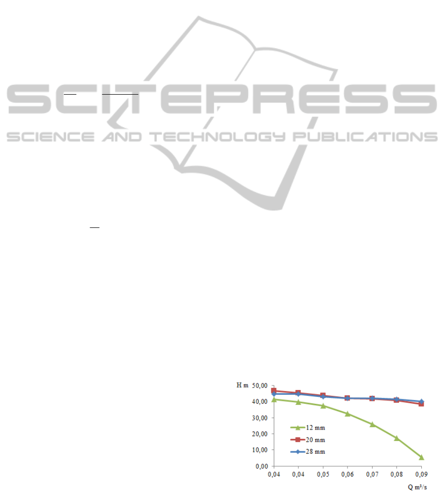
constant. Fig. 2 shows the pump head as a function
of the volume flow rate with the outlet blade height
as a parameter. There, it is observed that the pump
head increases with increasing blade height until a
certain value of the blade height. This can be
explained by the fact that when the volume flow rate
is kept constant, the increased outlet blade height
leads to the decreasing meridional velocity, which
increases the pump head since the outlet tangential
velocity and the outlet blade angle remain constant.
But when the meridional velocity becomes too small
or zero with increasing blade height, its influence to
the pump head is negligible.
The curves expressing the pump brake
horsepower as a function of the volume flow rate are
shown in Fig. 3, illustrating that the brake
horsepower increases relative to the increased blade
height due to the requested increase in pump shaft
torque relative to the increased blade height.
Moreover, Fig. 4 shows the overall efficiency
curves as a function of the volume flow rate. It can
be seen that the overall efficiency for b
2
= 12 mm
decreases rapidly to the right of the best efficiency
point (BEP). The overall efficiency curves for b
2
=
20 mm and 28 mm increase with increasing volume
flow rate.
Figure 2: Pump head versus volume flow rate.
SIMULTECH2012-2ndInternationalConferenceonSimulationandModelingMethodologies,Technologiesand
Applications
344
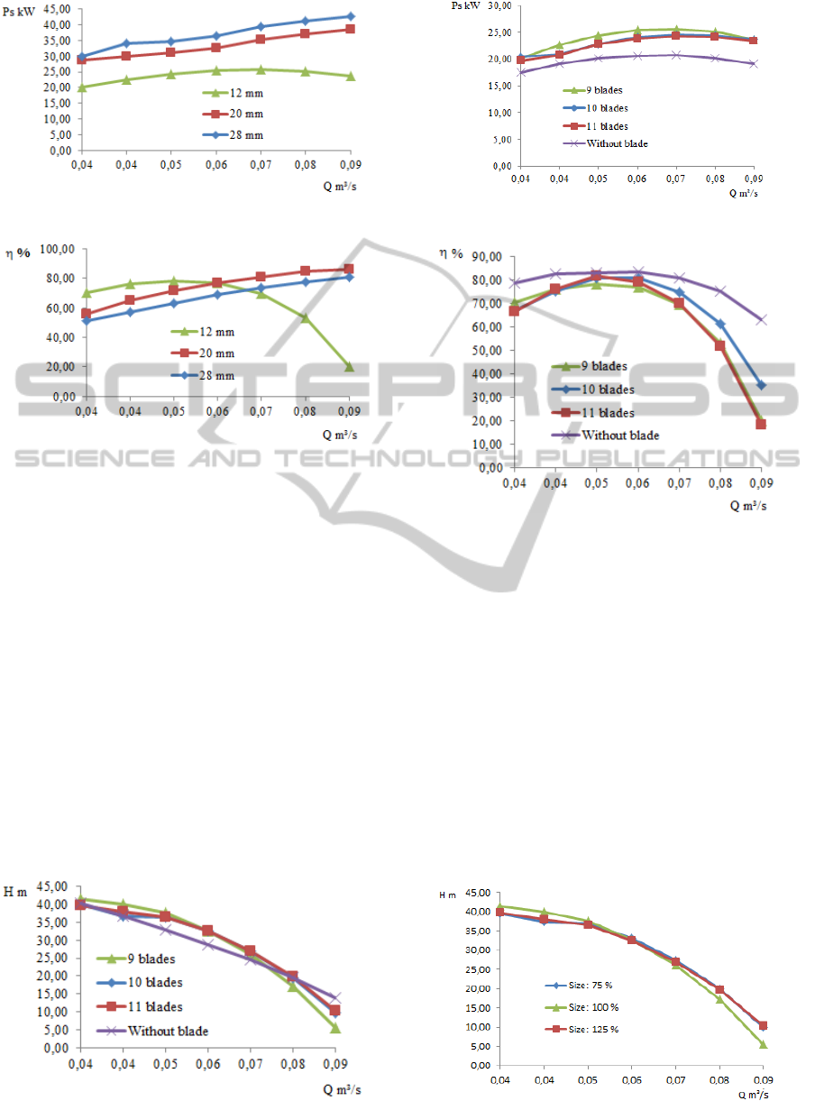
Figure 3: Brake horsepower versus volume flow rate.
Figure 4: Overall efficiency versus volume flow rate.
3.2 Effect of Diffuser Blade Number
To analyze the effect of the diffuser blade number
on the pump performance, a diffuser model without
blade and three other diffuser models with blade
numbers of 9, 10 and 11 were selected, while the
other parameters were kept constant. Fig. 5 shows
the pump head as a function of the volume flow rate,
where it is observed that the impact of the diffuser
blade number on the pump head is small. In
addition, Fig. 6 shows that the brake horsepower for
the case of a diffuser with blades is higher than the
case of a diffuser without blade. This can be
explained by the fact that the flow restriction due the
blades leads to a higher requested impeller shaft
torque. Furthermore, Fig. 7 shows that for the low
and the high volume flow rates, the overall
efficiency for the diffuser without blade is highest.
Figure 5: Pump head versus volume flow rate.
Figure 6: Brake horsepower versus volume flow rate.
Figure 7: Overall efficiency versus volume flow rate.
3.3 Effect of Volute Size
To investigate the effect of the volute size on the
pump performance, three values of 75 %, 100% and
125 % were selected for the volute size, while the
other parameters were kept constant. The value of
100% was considered as the volute size reference.
Fig. 8 indicates the pump head as a function of the
volume flow rate, illustrating that the influence of
the volute size on the pump head is small. The
corresponding curves for the brake horsepower and
the overall efficient are shown in Figs. 9 and 10
respectively, there it can be observed that the pump
with a volute size of 75 % requests lowest impeller
shaft torque and its overall efficiency is highest.
Figure 8: Pump head versus volume flow rate.
ParametricStudyofComplexLiquidFlowinaCentrifugalPumpConsistingofanImpeller,aVoluteandaDiffuser
345
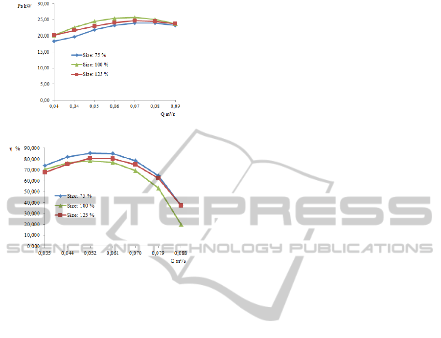
Figure 9: Brake horsepower versus volume flow rate.
Figure 10: Overall efficiency versus blade number.
4 CONCLUSIONS
In this study, a complex liquid flow model in a
centrifugal pump consisting of an impeller, a
diffuser and a volute was developed to analyze the
effects of the blade height, the diffuser blade
number, and the volute size on the pump head, the
brake horsepower and the overall efficiency. The
obtained results for considered value ranges
demonstrate, among others, that the pump head and
the brake horsepower increase with increasing blade
height. The pump performance is influenced by the
variation in volute size. Additionally, the results
comparison between the pump model having a
diffuser with blades and the pump model with a
diffuser without blade reveals that, for the case of a
diffuser without blade, the requested impeller shaft
torque is lower and the overall efficiency is higher
that the case of a pump having a diffuser with
blades. Further research work is planned to complete
this study comparing numerical simulation results
with various experimental values obtained from a
pump manufacturer, and optimizing the developed
model.
ACKNOWLEDGEMENTS
The authors are grateful to the Foundation of
University of Quebec in Abitibi-Temiscamingue
(FUQAT) and the company Technosub inc.
REFERENCES
Peng, W, 2008. Fundamentals of turbomachinery.
Hoboken, New Jersey, John Wiley and Sons.
Cheah, K. W, Lee, T. S., S. H. Winoto, and Z. M. Zhao,
2007. Numerical Flow Simulation in a Centrifugal
Pump at Design and Off-Design Conditions. Hindawi
Publishing Corporation International Journal of
Rotating Machinery, Volume 2007, Article ID 83641,
8 pages.
Djerroud, M., Dituba Ngoma, G., and Ghie, W., 2011.
Numerical Identification of Key Design Parameters
Enhancing the Centrifugal Pump Performance:
Impeller, Impeller-Volute, and Impeller-Diffuser,
ISRN Mechanical Engineering, vol. 2011, Article ID
794341, 16 pages, 2011. doi:10.5402/2011/794341.
Ozturk A., Aydin, K., Sahin, B., and Pinarbasi, A., 2009.
Effect of impeller-diffuser radial gap ratio in a
centrifugal pump. Journal of Scientific and Industrial
Research, Vol. 68, 203-213.
Ansys inc., 2008. ANSYS-CFX, User Manual USA.
SIMULTECH2012-2ndInternationalConferenceonSimulationandModelingMethodologies,Technologiesand
Applications
346
