Simultaneous Control of Translational and Rotational Motion
for Autonomous Omnidirectional Mobile Robot
2
nd
Report: Robot Model Considering Moving Parts
and Evaluation of Movable Area by Heights
Ayanori Yorozu, Takafumi Suzuki, Matsumura Tetsuya and Masaki Takahashi
Department of System Design Engineering, Keio University, 3-14-1 Hiyoshi, Kohoku-ku, Yokohama 223-8522, Japan
Keywords: Service Robot, Obstacle Avoidance, Omnidirectional Platform, Fuzzy Potential Method.
Abstract: This paper presents a real time collision avoidance method for an autonomous omnidirectional mobile robot
considering shape of the robot and movable area by heights based on simultaneous control of translational
and rotational motion. Service robots which have been developed in recent years have arms to work and
execute tasks. In these robots, the size of width is sometimes not equal to that of length by heights. In order
to avoid obstacles considering safety and mobility for the robots, it is necessary to evaluate shape of the
robot and movable area by heights. To evaluate them, the robot model is defined in heights of each moving
part. Evaluating of the robot model and the movable area for each height, if the robot is unable to move
keeping a safe distance from the obstacles, the robot determines the suitable orientation angle considering
the minimum length from the center of the robot model to that outer shape. In this paper, the novel control
method based on the Fuzzy Potential Method is presented. To verify the effectiveness of the proposed
method, several numerical simulations are carried out.
1 INTRODUCTION
Recently, autonomous mobile robots work in human
living space have been studied and developed. Some
cases of these robots installation to public facilities
have been reported (Tiejun et al., 2005). These
robots sometimes have two arms so these robots can
be used for manipulation and human-robot
interaction (Kuindersma et al., 1999), (Mehling et al.,
2007). In these robots, the size of width is not equal
to that of depth by heights. In order to avoid
obstacles considering safety and mobility, it is
necessary to consider moving parts and evaluate
shape of the robot and movable area by heights.
Various obstacle avoidance methods and their
availabilities for mobile robots have described
(Borenstein and Koren, 1991), (Minguez and
Montano, 2004). Most of these studies regard the
robots as points or circles and control methods of the
translational movements in two-dimensional plane
are discussed. However, depending on the shape of
the robot, this approach reduces and wastes available
free space and can decrease the possibility that the
robot reaches the goal. To enable wide robots to
avoid obstacles safely and efficiently, it is necessary
to control not only a translational motion but also a
rotational motion. Several studies have focused on
the orientation angle of the robot (Kavraki, 1995),
(Wang and Chirikjian, 2000). However, these
methods require an environmental map and the
studies have not shown the effectiveness for
avoidance of unknown obstacles by autonomous
mobile robots. Therefore, in our current research, to
avoid unknown obstacles reactively for wide robots,
simultaneous translational and rotational motion
control method is presented (Suzuki and Takahashi,
2011). In addition, there are obstacles of various
heights in the human living space and the relation
between the robot and the surrounding environment
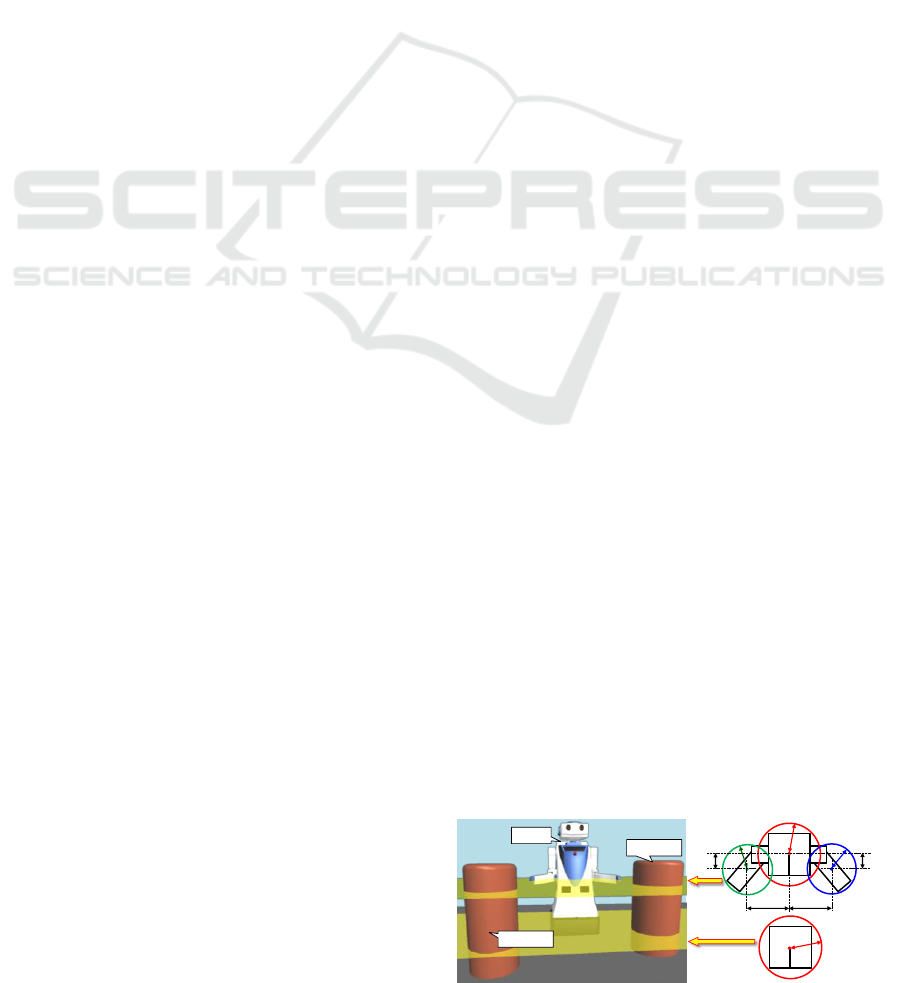
Figure 1: Proposed robot model considering moving parts.
Robot
Obstacle
Obstacle
C
Or
C
Or
C
Lr
P
O
P
O
P
L
P
R
C
Rd
C
Rw
C
Ld
C
Lw
C
Rr
451
Yorozu A., Suzuki T., Tetsuya M. and Takahashi M..
Simultaneous Control of Translational and Rotational Motion for Autonomous Omnidirectional Mobile Robot - 2nd Report: Robot Model Considering
Moving Parts and Evaluation of Movable Area by Heights.
DOI: 10.5220/0004035804510454
In Proceedings of the 9th International Conference on Informatics in Control, Automation and Robotics (ICINCO-2012), pages 451-454
ISBN: 978-989-8565-22-8
Copyright
c
2012 SCITEPRESS (Science and Technology Publications, Lda.)
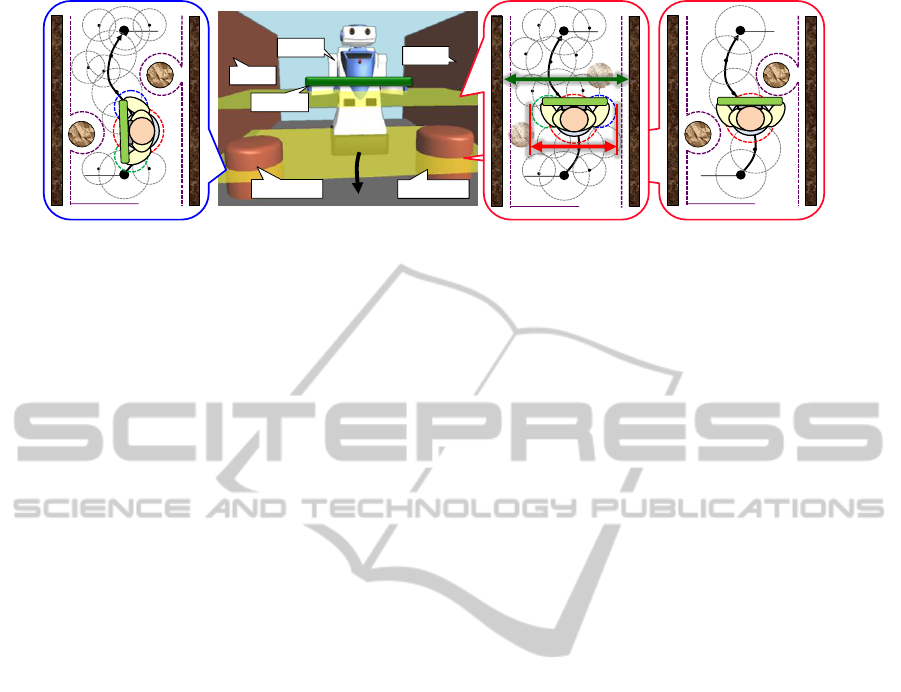
Figure 2: Trajectory of the robot with two motion control method: (left) considering footprint at the height of wheeled
platform, (right) evaluating shape of the robot and movable area by heights with robot model considering moving parts.
changes depending on shape of the robot. Therefore,
in order to avoid obstacles more safely and
efficiently, it is necessary to evaluate shape of the
robot and movable area by heights. Moreover, the
relation between the robot and the surrounding
environment is changed depending on the shape of
the robot by moving parts. Consequently, this study
proposes the following two points.
Robot model considering moving parts.
Simultaneous control of translational and
rotational motion considering shape of the
robot and movable area by heights.
With the proposed method, if the robot is unable to
move keeping a safe distance from the obstacles, the
robot determines the suitable orientation angle
considering the minimum length from the center of
the robot to that outer shape in real time. To verify
the effectiveness of the proposed method, several
simulations are carried out.
2 CONCEPT
For the robot which the size of width is not equal to
that of depth by heights according to moving parts,
in order to achieve obstacle avoidance considering
safety and mobility, it is necessary to evaluate shape
of the robot and movable area by heights.
2.1 Robot Model
To consider the changes of the shape of the robot by
moving parts, a new robot model with multi-circle
shown in Figure 1 is proposed. The modeling
method is as follows.
The model is defined at the heights that the
occupied area of each moving part is
maximum.
The robot body is enclosed by a circle.
The moving parts are enclosed in each circle.
With proposed robot model, changing the position of
the moving parts, the relation between the robot and
the environment is changed. Thus, performing the
motion control considering that point, as well as
translational and rotational motion control, the robot
can respond flexibly to various situations.
2.2 Motion Control Considering Shape
of the Robot and Movable Area by
Heights
Evaluating of the shape of the robot and the movable
area by heights, if the robot is unable to move
keeping a safe distance from the obstacles, the robot
determines the suitable orientation angle considering
the minimum length from the center of the robot to
that outer shape. Then, evaluation of the shape of the
robot and the movable area is used the width of the
robot model and the movable area measured with
range sensor like Laser Range Finder (LRF) by
heights. Considering the orientation angle in real
time based on the evaluation of the shape of the
robot and the movable area by heights, the robot can
move smoothly without unnecessary rotational
motion keeping a safe distance from obstacles like
Figure 2 (right).
In this study, the novel control method based on
the fuzzy potential method (FPM) (Tsuzaki and
Yoshida, 2003) is proposed. In the FPM, element
actions are represented as potential membership
functions (PMFs). The vertical axis of PMF
indicates the grade for the direction of the robot. The
PMFs for translational and rotational motion are
respectively designed by evaluating the shape of the
robot and movable area by heights. Finally,
translational and rotational velocity commands,
which are calculated by defuzzification of PMFs, are
realized by an omnidirectional drive system. (Suzuki
and Takahashi, 2011).
Robot
Obstacle
Obstacle
Wall
Wall
Safety area
Goal
Safety area
Start
Goal
Start
Safety area
Goal
Baggage
Start
ICINCO 2012 - 9th International Conference on Informatics in Control, Automation and Robotics
452
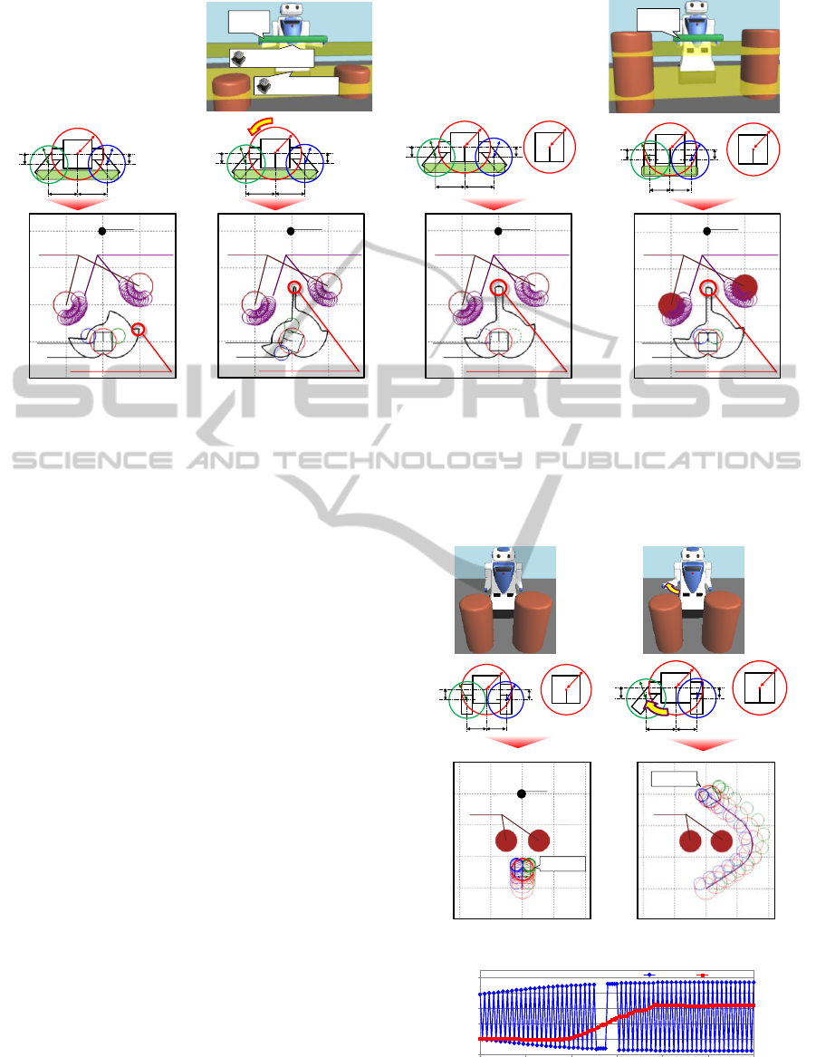
(a) Situation A
(b) Situation B
(c) Situation C
(d) Situation D
Figure 3: Aspects of the translational PMF and the traveling direction depending on the robot model and rotational motion.
3 SIMULATION
The robot has an omnidirectional drive system, and
can measure 4.0 m in
120deg
range at 0.23 m
height of the wheel platform and 0.60 m height of
arms with two LRFs. A safe distance for obstacles is
0.20 m. In situations A-D, the positions of two
obstacles that radius is 0.35 m were immobilized at
each point (-1.0 m, 1.0 m) and (1.0 m, 1.5 m) and
the robot transports baggage with arms, as shown in
Figure 3. On the other hand, in situations E and F,
the obstacles were immobilized (-0.5 m, 1.5 m) and
(0.5 m, 1.5 m) and the robot can open the forearms
at the height 2, as shown in Figure 4.
3.1 Effectiveness of Evaluation Shape
of the Robot and Movable Area by
Heights
In situations A-C, the height of obstacles is lower
than the robot arms. In situation A shown in Figure
(a), the robot cannot go through between the
obstacles keeping the safe distance from the
obstacles. As the result, the robot selected the
traveling direction toward the outside of the
obstacles to the goal. In situation B shown in Figure
3 (b), the rotational motion of the robot changes the
relation between the robot and the environment from
situation A. As the result, the robot can select the
traveling direction to go through between the
obstacles keeping the safe distance from the
obstacles. In situation C shown in Figure 3(c),
(a) Situation E
(b) Situation F
(c) Time history of the traveling direction.
Figure 4: Verification of the effectiveness of the proposed
robot model in a symmetrical environment.
Baggage
(1.0 m)
Height 1 (0.60 m)
Height 2 (0.23 m)
Baggage
(0.60 m)
Height 2
0.20 m
0.40 m
0.20 m
0.35 m
0.40 m
0.15 m0.15 m
Height 2
0.20 m
0.40 m
0.20 m
0.35 m
0.40 m
0.15 m0.15 m
70 deg
Height 1
Height 2
0.35 m
0.20 m
0.40 m
0.20 m
0.35 m
0.40 m
0.15 m0.15 m
Height 1 Height 2
0.35 m
0.20 m
0.20 m
0.20 m
0.35 m
0.20 m
0.15 m
0.15 m
1.0
-1.0
2.0-2.0
0.0
3.0
-1.0
0.0
1.0
2.0
x-coordinate [m]
y-coordinate [m]
Goal
PMF
Robot
Selected direction
Obstacle Obstacle margin
1.0
-1.0
2.0-2.0
0.0
3.0
-1.0
0.0
1.0
2.0
x-coordinate [m]
y-coordinate [m]
Goal
PMF
Robot
Selected direction
Obstacle Obstacle margin
1.0
-1.0
2.0-2.0
0.0
3.0
-1.0
0.0
1.0
2.0
x-coordinate [m]
y-coordinate [m]
Goal
PMF
Robot
Selected direction
Obstacle Obstacle margin
1.0
-1.0
2.0-2.0
0.0
3.0
-1.0
0.0
1.0
2.0
x-coordinate [m]
y-coordinate [m]
Goal
PMF
Robot
Selected direction
Obstacle Obstacle margin
Height 1 Height 2
0.35 m
0.20 m
0.20 m
0.20 m
0.35 m
0.20 m
0.15 m
0.15 m
Height 1
Height 2
0.35 m
0.20 m
0.40 m
0.20 m
0.35 m
0.20 m
0.15 m
0.15 m
1.0
-1.0
2.0-2.0
0.0
3.0
4.0
-1.0
0.0
1.0
2.0
x-coordinate [m]
y-coordinate [m]
Goal
t = 12.4 s
Obstacle
1.0
-1.0
2.0-2.0
0.0
3.0
4.0
-1.0
0.0
1.0
2.0
x-coordinate [m]
y-coordinate [m]
t = 12.4 s
Obstacle
-100
-60
-20
20
60
100
0.0 2.0 4.0 6.0 8.0 10.0 12.0
Traveling direction [deg]
Time [s]
Situation E Situation F
Simultaneous Control of Translational and Rotational Motion for Autonomous Omnidirectional Mobile Robot - 2nd Report:
Robot Model Considering Moving Parts and Evaluation of Movable Area by Heights
453

evaluating the shape of the robot and the movable
area by heights, the robot can select the traveling
direction to go through between the obstacles
keeping the safe distance from the obstacles without
unnecessary rotational motion like situation B. In
situation D shown in Figure 3(d), the height of
obstacles is higher than that of the robot arms. If the
shape of the robot at the height 1 is horizontally long
according to the baggage, the robot can go through
between the obstacles by rotational motion as well
as situation B. By contrast, in situation D that the
robot closes arms according to the size of the
baggage, the robot can select the traveling direction
to go through between the obstacles without
unnecessary rotational motion keeping the safe
distance from obstacles by evaluating the shape of
the robot by heights.
These results showed that it is possible for the
robot to select the traveling direction that makes a
short route to the goal keeping the safe distance from
obstacles by the evaluation of the shape of the robot
and the movable area by heights.
3.2 Effectiveness of Consideration of
Moving Parts
In situation E shown in Figures 4(a) and 4(c), the
robot cannot get to the goal because it is difficult to
determine the traveling direction uniquely only
using reactive motion control method in situation
that the surrounding environment of the robot is
completely symmetrical. By contrast, in situation F,
the robot changed the position of the moving part.
As shown in Figures 4(b) and 4(c), the robot can
deal with this problem by changing the relation
between the robot and the surrounding environment
depending on the position of the moving parts.
These results show that the robot becomes
possible to respond flexibly to various situations by
the proposed robot model because the choices of
method for motion control to change the relation
between the robot and the environment increase.
4 CONCLUSIONS
In this paper, toward the realization of motion
control for autonomous mobile robots that can be
flexible in various situations, the robot model
considering moving parts has been proposed. In
addition to translational and rotational motion, using
this robot model, it was verified that the changes of
the moving parts can change the relation between
the robot and the environment. Furthermore, the real
time collision avoidance method based on the fuzzy
potential method considering the shape of the robot
and the movable area by heights has been proposed.
Evaluating of the robot and the movable area for
each height, if the robot is unable to move keeping a
safe distance from the obstacles, the robot
determines the suitable orientation angle considering
the minimum length from the center of the robot
model to that outer shape. The effectiveness has
been verified by numerical simulations. It has been
shown that the robot becomes possible to respond
flexibly to various situations by proposed robot
model and control method.
REFERENCES
Tiejun, Z., Dalong, T. and Mingyang, Z. (2005). The
Development of a Mobile Humanoid Robot with
Varying Joint Stiffness Waist, Proceedings of the
IEEE International Conference on Mechatronics and
Automation, Vol. 3, pp.1402-1407.
Kuindersma, S., Hannigan, E., Ruiken, D. and Grupen, R.
(1999). MINERVA: Dexterous Mobility with the
uBot-5 Mobile Manipulator, Proceedings of the IEEE
International Conference on Robotics and Automa-
tion, Vol. 3, pp. 1999-2005.
Mehling, J. S., Strawser, P., Bridgwater, L., Verdeyen, W.
K. and Rovekamp, R. (2007). Centaur: NASA’s
Mobile Humanoid Designed for Field Work, IEEE
International Conference on Robotics and Automa-
tion, pp. 2928-2933.
Borenstein, J. and Koren, Y. (1991). The Vector Field
Histogram Fast Obstacle Avoidance for Mobile
Robots, IEEE Transactions on Robotics and Automa-
tion, Vol.7, No.3, pp.278-288.
Fox, D., Burgard, W. and Thrun, S. (1997). The Dynamic
Window Approach to Collision Avoidance, IEEE
Robotics and Automation, Vol. 4, No. 1, pp.1-23.
Minguez, J. and Montano, L. (2004). Nearness diagram
(ND) Navigation: Collision Avoidance in Trouble-
some Scenarios, IEEE Transactions on Robotics and
Automation, Vol. 20, No. 1, pp. 45-59.
Kavraki, L. (1995). Computation of Configuration Space
Obstacles Using the Fast Fourier Transform, IEEE
Transactions on Robotics and Automation, Vol. 11,
No. 3, pp. 408-413.
Wang, Y. and Chirikjian, G. S. (2000). A New Potential
Field Method for Robot Path Planning, Proceedings
IEEE International Conference on Robotics and Auto-
mation, San Francisco, CA, pp. 977-982.
Suzuki, T. and Takahashi, M. (2011). Translational and
Rotational Motion Control Considering Width for
Autonomous Mobile Robots Using Fuzzy Interence,
Numerical Analysis – Theory and Application, InTech
Book, ISBN 978-953-307-389-7.
Tsuzaki, R. and Yoshida, K. (2003). Motion Control
Based on Fuzzy Potential Method for
AutonomousMobile Robot with Omnidirectional
Vision. Journal of the Robotics Society of Japan,
Vol.21, No.6, pp.656-662.
ICINCO 2012 - 9th International Conference on Informatics in Control, Automation and Robotics
454
