
A Novel Approach to Measure under Water Vehicle Disturbance
Force for Station Keeping Control
J. Manecius Selvakumar and T. Asokan
Department of Engineering Design, Indian Institute of Technology, Chennai, 600 036, India
Keywords: Under Water Vehicles, Sensor Beam, Strain Gauge, Feedback Mechanism, Disturbance Force, Station
Keeping.
Abstract: Maintenance of target position and/or orientation is essential for underwater vehicles (UWV) to successfully
complete a mission. However, in the case of work class vehicles, station keeping becomes an important
issue due to the presence of disturbance forces and requires effective feedback mechanism to maintain the
pose. Conventionally, the changes in position due to disturbance force is monitored and fed back to the
station keeping controller to make necessary corrections. This introduces unnecessary delay in response and
continuous variations in vehicle position. In this paper, an attempt has been made to develop a disturbance
force measurement setup using strain gauges which will directly measure the disturbance forces which can
be used for predicting the vehicle pose disturbance and make necessary corrections even before the vehicle
starts responding to the disturbance forces. The methodology adopted for force measurement is presented
and experimental analysis has shown promising results. This approach can be used as an alternative
feedback mechanism for station keeping control of underwater Vehicles.
1 INTRODUCTION
Station keeping is the process by which an
underwater vehicle (UWV) is held in its desired
position resisting the external forces acting on it.
Ocean medium is subjected to deep sea currents
arising due to the changes in temperature and other
factors and hence it becomes difficult to control the
undesired movements of vehicles (Eric Conrado and
Maruyama, 2007).
For station keeping control of underwater
vehicles, the feedback information about the
disturbance acting on them is very essential (Woods,
et al., 1998). However, the delay in vehicle response
and feedback cause undesired movement of vehicle
before it is controlled (Antonelli, et. al., 2001). One
way to reduce this pose disturbance is to predict the
UWV motion from the disturbance forces acting and
then generate necessary control forces to nullify the
effects of the disturbance. This will facilitate an
UWV with faster position keeping capability. In this
paper, we propose a feed-forward station keeping
control using direct measurement of disturbance
forces. Since strain gauges are widely used in
underwater applications for force measurements
(McLain and Rocky, 1992), specially designed
measurement beams with strain-gauge sensors are
proposed here for the force measurement. The
design, analysis, and experimental details of the
force sensing system are presented in this paper. The
paper is organised in the following way. The station
keeping control strategy and its simulation results
are briefly described in section 2. Section 3 and 4
describes the disturbance velocity measurement
setup. Experimentations details are covered in
section 5. The results of the sensor beam testing are
discussed in section 6.
2 CONTROL STRATEGY
The proposed control strategy is to equip the UWV
with sensors to measure the disturbance forces
acting on it and predict the resultant velocity to use
this as a feed-forward data for control. Assuming
that the disturbance forces due to underwater current
are negligible in the vertical direction, a planar
station keeping strategy is proposed. Force sensors
are attached to the UWV on all four sides and the
disturbance force is measured and sent to the
controller. Using the dynamic model of the vehicle,
the resulting velocity of the vehicle due to the
460
Manecius Selvakumar J. and Asokan T..
A Novel Approach to Measure under Water Vehicle Disturbance Force for Station Keeping Control.
DOI: 10.5220/0004036704600463
In Proceedings of the 9th International Conference on Informatics in Control, Automation and Robotics (ICINCO-2012), pages 460-463
ISBN: 978-989-8565-22-8
Copyright
c
2012 SCITEPRESS (Science and Technology Publications, Lda.)
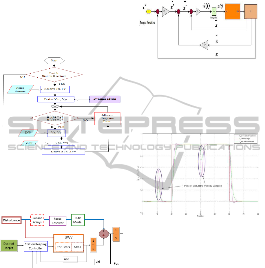
disturbance is predicted and fed to the controller as a
feed forward data. Control action is initiated by the
controller to overcome the effects of vehicle velocity
resulting from the disturbance force. Figure 1 shows
the flow chart for the above strategy. If needed, in
addition to the predicted response of the vehicle,
actual pose of the vehicle can also be used for
generating the control forces.
Figure 1: Control Scheme using Disturbance Force data.
Figure 2 shows the proposed station keeping
control methodology using the measured force. To
execute the correction in account of vehicle’s
dynamics, the conventional motion reference unit
(MRU) data is used.
Figure 2: Proposed Control Method.
The motion control algorithm based on Inverse
Dynamic Task theory (Krut’ko., 1989) is
represented in figure 3. This algorithm drives the
control function using the vehicle’s motion
parameters and is used in the station keeping control
task.
The performance of the developed control
method has been analyzed. The following is the
sample result of the simulation. Figure 4 shows the
desired position, actual position without feed
forward and with feed forward controller in x-axis.
The simulation was done for the disturbing current
Figure 3: Vehicle motion controller.
velocity which changes its magnitude and direction
at 10 sec and 40 sec. It is inferred that with the feed
forward method, the deviation from desired target
and the settling time are reduced to 50% than the
original case of performance without feed forward
loop. The simulation result reveals that the existence
of feed forward loop improves the position control
action.
Figure 4: Controller Response.
3 DISTURBANCE VELOCITY
MEASUREMENT
A prototype vehicle designed for laboratory level
experimental studies is used here for verification of
the strategy. Force sensors are arranged on the
vehicle as shown in figure 5. As a first step, the
measurement of disturbances forces arising out of
the currents is measured using this setup. The solid
model of the Experimental Underwater Vehicle
(EUWV) with its major subcomponents is shown in
figure 5.
Since measurement of disturbance force is a
major consideration in this method, the optimal
orientation and position of the sensor beam is
essential and will be decided based on the results of
the performance test of the EUWV with sensor
beam.
EUWV
MRU
A Novel Approach to Measure under Water Vehicle Disturbance Force for Station Keeping Control
461
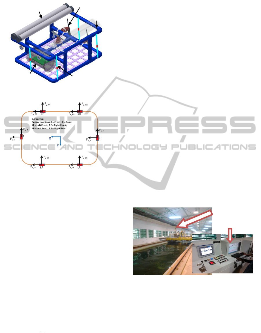
Figure 5: Solid Model of EUWV with sensor setup.
Figure 6: Sensor Beams and Forces.
Locations of sensor beams with their significant
measurement axis and force components are
indicated in figure 6. Since, the orientation of sensor
beams F and R are perpendicular to X axis, the F
y_F
and F
y_R
are insignificant. Similarly, F
x_LF
, F
x_LR
,
F
x_RF
and F
x_RR
are also insignificant. The resultant
force in x and y axis is calculated by averaging the
force measured by the number of significant sensors
in the respective axis.
4 MEASUREMENT SETUP
The sensor beam of dimension: length (L) 300 mm,
breadth (b) 20 mm, and thickness (t) 3 mm has been
designed and used in testing.
The theoretical strain resulting from the forces
acting on the UWV is calculated as follows:
Drag force on the beam due to the current
velocity is given as (Blevins and Robert, 2003)
dd
CAVF
2
2
1
(N)
(1)
where, density of water, ρ = 1000 kg/m
3
V – Speed of the object relative to the fluid (m/s)
A – Area of the object = L x b (m
2
)
C
d
– Coefficient of drag = 1.28 (Source: “Shape
Effect on Drag” at Glenn Research Centre,
NASA)
The pressure on the beam P = F
d
/A (N/m
2
) and
load per unit length w = P *b (N/m) is calculated and
the strain is calculated using Hooks law as:
ε.E = σ
b
(2)
where, ε is the strain acting on the beam, σ
b
is the
stress and E is young’s modulus of acrylic material
(Johnson and Devenport, 2007).
Confirmation of appropriate thickness, width and
the strength of the acrylic sensor beam are done by
analysis and analytical calculation. Two metal foil
strain gauges of Gauge factor (GF) 2.09 (placed on
the opposing sides and connected to half bridge
circuitry) are used for measurement of the actual
forces acting on the beam. (Hoffmann, 1889)
(Kleckers, 2004) (Schäfer, 2004).
5 TESTING OF SENSOR BEAM
Deflection members made up of Aluminium,
Stainless Steel and Acrylic were fabricated and
calibrated by the laboratory standard method
(William A. Lokos and Rick Stauf, 2004). Based on
the results of this, acrylic was chosen as the material
for sensor beam.
Figure 7: Towing Tank Facility.
Testing of the developed sensor beam was
carried out in towing tank of Ocean Engineering
Department at the Indian Institute of Technology
Madras. The carriage used for the tests has
dimension of 85 m x 3.2 m x 2.5 m and has variable
carriage speed from 0 m/s to maximum 5 m/s.
(figure 7).
In the above said towing tank testing, two
identical sensor beams as shown in Figure 8, were
fixed on the carriage and interfaced with the
instrumentation amplifier.
Data Logger PC and
Trolley Control
Panel
Electronic Housing
Thruster
Additional Buoyancy
Main Frame (PVC)
Sensor Beam
ICINCO 2012 - 9th International Conference on Informatics in Control, Automation and Robotics
462
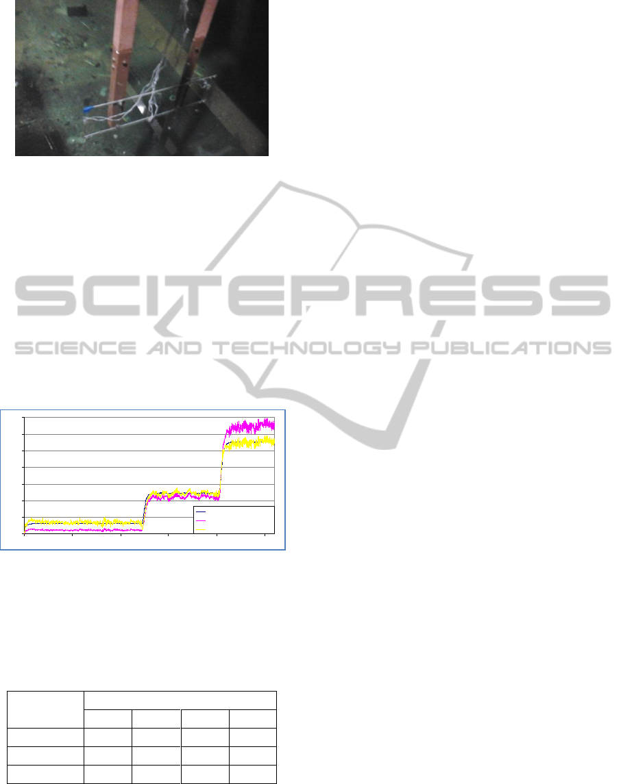
Figure 8: Test Setup – Three Sensor Beams.
6 RESULTS AND DISCUSSION
The experiments were carried out by varying the
speed of towing trolley from 0 knot to 1 knot with
the step increase of 0.5 knot (0.25 m/s).
The result for one of the tests is shown in Figure
9, which shows the comparison of theoretical strain
and the measured strain on the 50 mm width beam
(the graphs in this section are plotted based on the
data points, however, one can easily identify the
speed increase from 0.5 knot to 1 knot and then to
1.5 knots from the graphs).
Figure 9: Results_50 mm Sensor Beam 1.
As the measured strain has constant offset from
actual, we propose to use correction factors as listed
in table 1 to use while using the output of sensor
beam for control of the EUWV.
Table 1: Correction Factors of Sensor Beams.
Width Speed
(m/s)
Correction Factor
20 mm
30 mm
40 mm
50 mm
0.25
2.5
2.05
2
3
0.5
1.25
1.4
1.4
1
0.75
0.625
1.025
1.125
0.825
Using the conventional relationship of force and
strain, the disturbing current velocity is derived
using the strain measured from the sensor beams.
7 CONCLUSIONS
Development of a disturbance velocity measurement
setup using strain gauges is presented in this paper.
Feed forward control strategy and simulation study
showing performance of the proposed control
scheme are presented. Study on the performance of
developed sensor setup of varying thickness and
width has been carried out. Acrylic sensor beam
having 2 mm thickness is selected to use for
implementation and experimental validation of
proposed control scheme. Derived correction factors
for the sensor beams will be used during further
experiments. This method of disturbance force
measurements can be effectively used for station
keeping control of AUVs.
REFERENCES
André Schäfer, Dr.-Ing, 2004, Force, Strain and Pressure
transducers based on foil type strain gauges, HBM
GmbH, Darmstadt, Germany.
Antonelli G., Chiaverini S., Sarkar N. & West M., 2001,
Adaptive control of an autonomous underwater
vehicle: experimental results on ODIN, In
Transactions on Control Systems Technology, IEEE,
Sep 2001.
Blevins, Robert D., 2003, Applied Fluid Dynamics
Handbook. Krieger Publishing Co.
Eric Conrado De Souza, Newton Maruyama, 2007,
Intelligent UUVs: Some Issues on ROV Dynamic
Positioning, In IEEE Transactions on Aerospace and
Electronic Systems.
Eric R. Johnson and William J. Devenport, 2007, Static
Response of a Beam, in experimental manual.
Hoffmann K., 1889, An introduction to measurements
using strain gauges, Hottinger Baldwin Messtechnik
Publisher.
Krut’ko. P. D., 1989, Inverse problems of control system
dynamics: nonlinear models, Nauka Phys. & Math
Publisher, Moscow.
McLain T. W., Rocky S. M., 1992, Experimental
Measurement of ROV Tether Tension, In Proceedings
of ROV, San Diego, CA.
Thomas Kleckers, 2004, Important characteristics of force
transducers, HBM GmbH, Darmstadt, Germany
William A. Lokos, Rick Stauf, 2004, Strain-Gauge Loads
Calibration Parametric Study, In Technical Report of
NASA Centre for Aero Space Information (CASI).
Woods A. J., Penrose J. D., Duncan A. J., Koch R., Clark
D., 1998, Improving the Operability of Remotely
Operated Vehicles, In Appea Journal, pp 849 – 854.
Strain_50 mm Sensor Beam 1
0
200
400
600
800
1000
1200
1400
0 500 1000 1500 2000 2500
Data Points
Strain (MicroStrain)
50_SB1_Theory
50_SB1_Experiment
50_SB1_Exp. With CF
A Novel Approach to Measure under Water Vehicle Disturbance Force for Station Keeping Control
463
