
Integral Sliding Mode and Second Order Sliding Mode Attitude and
Altitude Tracking of a Quadrotor System
Theory and Experiment
Mouloud Bouchoucha, Abdessamed Boudane, Kamel Ali
and Sofiane Seghour
Laboratoire de Côntrole & Commande (LCC), Ecole Militaire Polytechnique(EMP),
Bordj-El-Bahri, Algiers, 16111, Algeria
Keywords: dsPIC, Dynamic Modeling, Embedded Control System, IMU, Integral Sliding Mode, Quadrotor, Second
Order Sliding Mode, Super- Twisting , UAV, C.
Abstract: In this paper Attitude and Altitude tracking control design of the four rotors helicopter will be considered.
Two robust control algorithms will be designed for the case of stabilization and tacking of attitude and
altitude system’s outputs. The attitude controller is realized using an inertial measurement unit (IMU) based
on MEMS sensors. The altitude control algorithm uses a sonar sensor output. The control algorithms
designed are implemented on an embedded control system based on a dsPIC C. The obtained experimental
results demonstrate high performance of both controllers and robustness against disturbances.
1 INTRODUCTION
Unmanned Aerial Vehicles (UAVs) have been
designed in the military field since more than one
half century. The main objective was to replace
human pilot in a painful tasks and when the
environment became hostile where the security of
pilots is not assured such as: intervention in hostile
environment, management of the natural risks,
exploration of high buildings or contaminated
tunnels, surveillance, rescue missions, movie filming,
which were not possible before.
Nowadays, researches in this field know a very
big progress with the advance development of
electronic and digital systems. This progress has
given birth to low cost very small and accurate
electronic components, a powerful calculators, and
sensors. All these, aimed to product a small
embedded, autonomous and intelligent systems, able
to perform missions with more effectiveness and
reliability.
Miniature Vertical Takeoff and landing (VTOL)
unmanned aerial vehicles (UAV's) offer challenging
benchmark control problems and have been the
focus for many researchers in the past few years
(Brisset, 2004), (Bouabdallah, 2007). The VTOL
UAV four rotor helicopter named X4, OS4, or
known commonly as a quadrotor shown in Figure
1, is a mini-aircraft with four propellers.
Many researches addressed the modeling, the
control, and the design of the quadrotor system
(Bouabdallah, 2007), (Bouabdallah et al., 2004),
(Escareño et al., 2006), (Osmani et al., 2010),
(Hoffmann et al., 2007), (Kroo and Prinz, 2000),
(Derafa, 2006), (Hanford, 2005), (Hamel et al.,
2002), (McGilvray, 2004), (Bouadi et al., 2007),
(Bouchoucha et al., 2008).
Generally speaking, improving the performance
requires a good knowledge of the model as it is the
case with the almost previous aforementioned works.
Nevertheless it is still possible to achieve robustness
and a highly efficient dynamics using a control
techniques that does not need a good knowledge of
the model; this is the case especially where some
dynamics are neglected, the system parameters are
variable or not known exactly (inertia, thrust and
drag coefficients), or the system is subject to a
disturbance like the wind guest. To overcome to that,
robust control techniques have been proposed
(Bouchoucha et al., 2008), (Waslander et al., 2006),
(Bouabdallah et al., 2005), (Bouchoucha et al.,
2011), (Seghour et al. 2011)..etc. Almost the
designed techniques use sliding mode control
technique and/or they implement only the attitude
dynamics.
In this work, two control techniques are designed
266
Bouchoucha M., Boudane A., Ali K. and Seghour S..
Integral Sliding Mode and Second Order Sliding Mode Attitude and Altitude Tracking of a Quadrotor System - Theory and Experiment.
DOI: 10.5220/0004038002660273
In Proceedings of the 9th International Conference on Informatics in Control, Automation and Robotics (ICINCO-2012), pages 266-273
ISBN: 978-989-8565-22-8
Copyright
c
2012 SCITEPRESS (Science and Technology Publications, Lda.)
for the stabilization and the tracking of the attitude
and the altitude of the quadrotor system; the integral
sliding mode (ISM) and the second order sliding
mode (SOSM). The benefit is to demonstrate the
ability of both techniques to stabilize the system and
the ability of the second order technique to eliminate
the chattering phenomena while preserving the
performance comparing with the classical sliding
mode. The algorithms of both techniques are
implemented in real time on a developed embedded
control system based on a dsPIC µC to a quadrotor
platform (a modified version of the Draganflyer of
RCTOYS (Figure1)).
The rest of the paper is organized as follows: in
section 2, a mathematic model of the quadrotor is
presented. Section 3 is devoted to the design of both
control approaches for the attitude and the altitude
system’s outputs. Real time implementation results
of both control algorithms are presented in section 4.
Finally, conclusions are made in section 5.
2 DEFINITION AND
DYNAMICAL MODEL
A Quadrotor is an aircraft that is propelled by four
rotors. This model of rotary wing vehicles is very
interesting since the characteristic of taking-off and
landing so the space of their maneuvers is very
limited while comparing with fixed- wing aircraft.
The motion of this vehicle is controlled by
varying the rotating speed of the four rotors to
change the thrust and torques produced by each one.
The front and rear motors rotate counter clockwise,
while the two other motors rotate clockwise in order
to counter the yaw torque produced at the movement
of the aircraft (McGilvray, 2004), (Tayebi and
McGilvray, 2004). The main thrust derives from the
sum of thrusts of each rotor; it creates the vertical
motion of the platform. The pitch and roll torques
are derived respectively from the differences
and
, while
is the thrust force
of the rotor “i”. The roll and pitch inclination create
the translational motion along X and Y axis
respectively.
The yaw torque is the sum of the reaction torques
of each rotor produced by the shaft acceleration and
the blade’s drag
with
,
is the drag coefficient and
is the
propeller speed of the motor i (Osmani et al., 2010),
(Hanford, 2005).
The force
produced by the rotor “i” is
proportional to the square of the propeller speed,
(a)
(b)
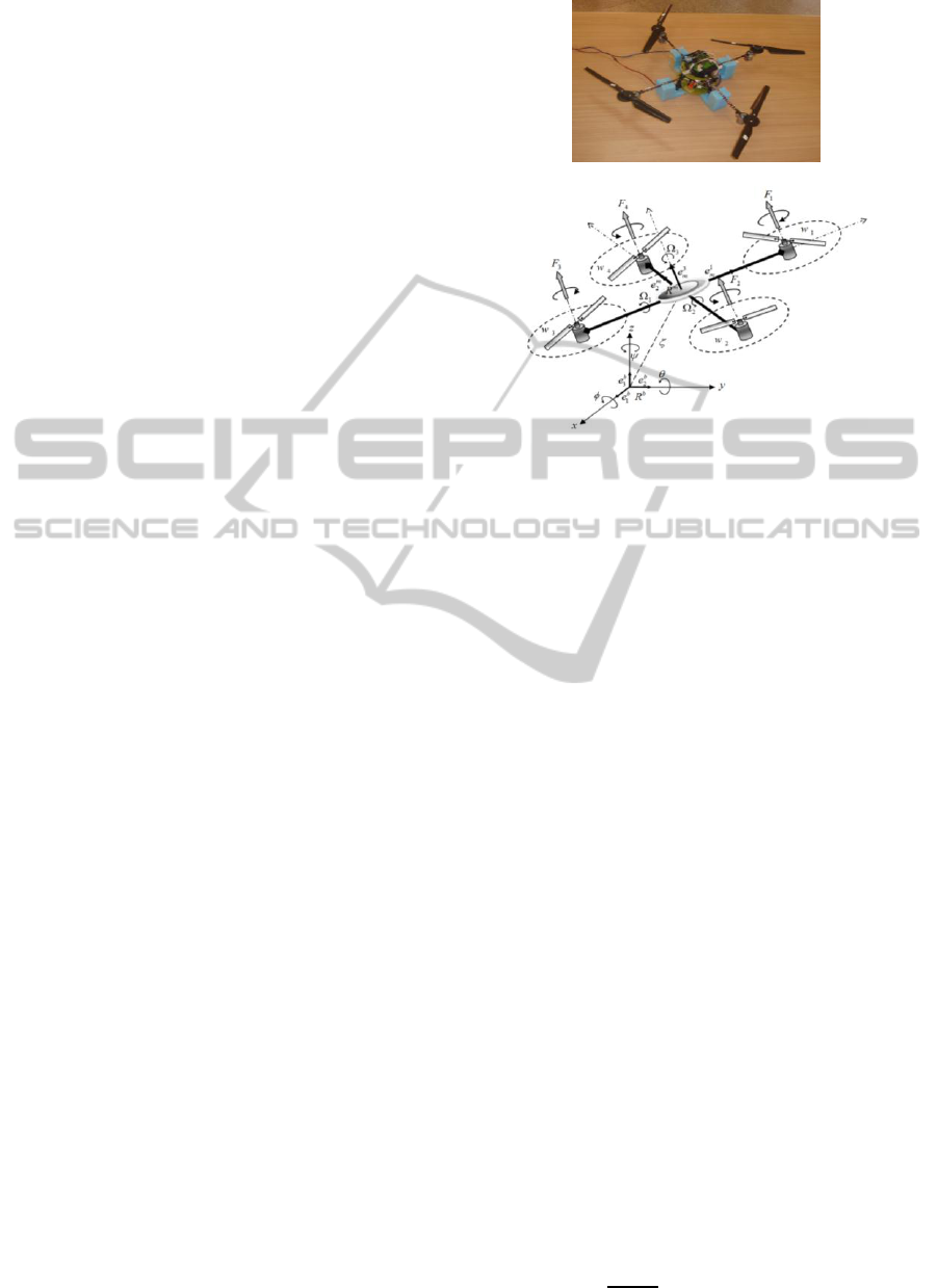
Figure 1: (a) Quadrotor helicopter of the LCC laboratory
(EMP), (b) Quadrotor configuration and principles.
with the proportionality constant of the
thrust force.
The dynamics of the quadrotor is described in the
space by six degrees of freedom according to the
fixed inertial frame related to the ground.
To derive the dynamic model of the quadrotor,
the Newton Euler formalism will be used on both
translation and rotation motions; therefore to obtain
the following equations (Hamel et al., 2002),
(Bouabdallah et al., 2004), (McGilvray, 2004),
(Derafa, 2006).
JJ
mFFF
v
gaf
gdtf
(1)
In this work we mainly focus our interest to the
attitude and the altitude dynamics and we consider
the state space model of reduced dynamical model to
simplify the control design as follows (Bouabdallah
et al., 2004), (Derafa, 2006), (Boudane and Kamel,
2011):
(2)
Integral Sliding Mode and Second Order Sliding Mode Attitude and Altitude Tracking of a Quadrotor System - Theory and
Experiment
267

Where
.
And the control inputs:
(3)
and
are the roll, the
pitch, the yaw, the altitude and their variations
respectively.
The parameters
depend on the mass
and the inertia of the system, the inertia of the rotors,
the aerodynamic friction coefficients, the drag
coefficients of translation.
The parameters
depend on the inertia of the
system and the distance between the center of the
system and the center of the rotor; and the parameter
depend on the inertia of the system.
is the total mass of the quadrotor and is the
gravitational acceleration.
S and C represent the Sinus and Co-sinus
functions respectively.
The rotors are driven by DC-motors with the well
known equations (McGilvray, 2004), (Bouabdallah
et al., 2004):
(4)
Where R
a
, I
a
, k
m,
L,
mi
and τ
i
are the motor
resistance, armature current, motor constant,
armature inductance, motor speed and the rotor
torque respectively.
3 CONTROL LAWS DESIGN
This section is focused to the design of both control
techniques proposed in this work i.e. the integral
sliding mode and the second order sliding mode for
the stabilization of the attitude and the altitude
outputs of the quadrotor system.
Before presenting the design of both controls
which is considered as an external loop we will
present the control of each rotor i.e the propeller
speed (internal loop).
The control torque developed by motor is a
proportional controller with compensation of the
drag torque resulting of the rotation of the propeller
(McGilvray, 2004).
3.1 Control Design of the Quadrotor
Dynamic
In order to stabilize the attitude and the altitude of
the qaudrotor system, two robust control approaches
will be designed: the integral sliding mode and the
second order sliding mode. The benefit within the
use of the integral term in the integral sliding mode
is to improve the tracking errors.
To simplifier the demonstration of the design of
both control approaches, the model of the qaudrotor
presented in (2) can be rewritten as:
(5)
With
and
3.2 Integral Sliding-mode Control
Approach
In this section we use Backstepping technique to
design the integral sliding mode control. The benefit
is the systematic choice of the Lyapunov function in
the stability demonstration. The Backstepping
control technique is designed for a system in
triangular feedback form which is the case for the
dynamic model of the quadrotor. In this technique
the control design pass by several steps, in each step
the actual state is controlled by the next state as a
virtual control, until the last state which is controlled
by the real control. The integral sliding mode
(Skjetne and Fossen, 2004) is the well known sliding
mode robust control (Utkin, 1978) augmented by an
integral term to improve the tracking errors.
However this approach suffers from the chattering
phenomena that limit its realization.
The integral sliding mode will be designed for
the stabilization of the attitude and the altitude of the
qaudrotor model (5) in two steps.
The first step in this design is similar to the one
for the Backstepping approach.
The most common way to include integral action
in Backstepping is to use parameter adaptation.
Another method is to augment the plant dynamics
with the integral state
(Skjetne and
Fossen, 2004). The resulting system is still in strict
feedback form; however, the vector relative degree
is increased to 3.
(6)
ICINCO 2012 - 9th International Conference on Informatics in Control, Automation and Robotics
268

Step 1: in this step we consider the subsystem:
And one define a new state
such as:
, and we introduce the first Lyapunov
function candidate :
Its time derivative is give by:
If we apply the Lyapunov theorem, i.e. by
imposing
condition, the stabilization of
and
can be obtained by introducing a new virtual
control input
where:
with
Step 2: Here we define the sliding surface
(Surface) [15]:
(7)
And we consider the augmented Lyapunov
function:
(8)
The chosen law for the attractive surface is the
time derivative of
satisfying (
):
(9)
In the other hand we have:
As for the Backstepping approach, the control
is extracted as follow:
(10)
And the resulting control laws are given by:
(11)
In the implementation, the sign (signe) function is
replaced by the Sat function in a boundary Layer
(Slotine, 1985) to reduce the chattering problem.
3.3 Second Order Sliding Mode Control
(Super-Twisting Algorithm)
The attitude and the altitude dynamic of the
quadrotor in (2 model) or (5) have relative degree
one with respect to the sliding surface defined in
(12) (the control input appears in the first derivative
of the sliding surface (14)). To remedy of the
chattering phenomena in classical integral sliding
mode, the second order sliding mode by using the
super-twisting algorithm will be applied (Levant,
1997), (Emelyanov et al., 1986), (Emelyanov et al.,
1996), (Fridman and Levant, 1996), (Nollet et al.,
2008).
Let us define here a new sliding surface
of
the system based on the model of the form (6)
without the first equation:
, with
(12)
Its time derivative is given by:
(13)
Replacing
by its equation given in (5) or (6),
become:
(14)
Using the principle of second order sliding mode by
the super-twisting algorithm (Bouchoucha et al.,
2011), (Nollet et al., 2008) the control input
is
given by:
(15)
With
With the super-twisting controls
are
given by:
(16)
(17)
Finally the control inputs
are given by:
(18)
Choosing the values of
and
sufficiently large,
allow to the tracking errors
and
to tend to zero
in finite time. The robustness to the parametric
uncertainties can be ensured by increasing the gains
and
(Slotine, 1985).
4 REAL TIME
IMPLEMENTATION
4.1 Experimental Setup
In order to validate the control laws developed in the
Integral Sliding Mode and Second Order Sliding Mode Attitude and Altitude Tracking of a Quadrotor System - Theory and
Experiment
269
previous section, we implemented the controllers on
the embedded control unit based on a dsPIC µC. The
attitude outputs are measured using the IMU 3DM-
GX1 of microstrain and the altitude is measured by
the ultrasonic sensor SRF08. The propellers speeds
are measured using a Hall Effect sensor combined
with little magnets mounted under the main rotor
gear. The sampling period is 30ms for the attitude
motion and 65ms for the altitude motion (the
ultrasonic sensor give the output each 65ms). We are
made for both control laws two experiment. In the
first experiment the attitude motion is stabilized with
a fixed trust U1=2.6N and the system is mounted on
fixed base knee-joint. In the second experiment
where we will give it a great interest we have
liberated the system to stabilize its altitude with
attitude is stabilized around an equilibrium point
zero. The controller’s parameters for both controllers
were tuned by trial and error, until obtaining a better
responses performance of the system.
4.2 Attitude Motion
For both control law and for the case of stabilization
around the equilibrium point and for more
convenience the initial values for the roll, pitch, and
yaw angles are taken almost the same for both
controllers.
The results obtained for both controllers are
shown in the figure.2
The following graphs show the obtained
performances:
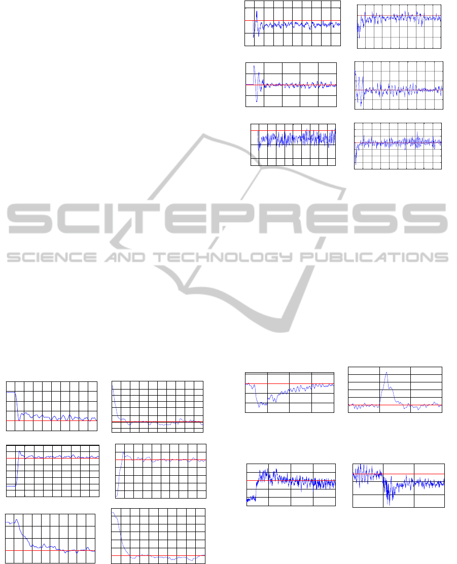
Figure 2: Attitude stabilization :(left) integral sliding mode
(ISM), (right) second order sliding mode (SOSM).
The results obtained demonstrate the stabilization
of all the system outputs for both controllers.
Figure 3: Control inputs: (left) ISM, (right) SOSM.
However the second order sliding mode
demonstrates more superiority in term of
performance (settling time and accuracy).
To test the robustness of both approaches two
experiments have been performed.
In the first experiment the robustness test have
been realized to deal with the external load
disturbance and for more convenience, we have
maintained the same work conditions; a mass of 50 g
is fixed on the end of the system axis. The test is
made for the roll and the pitch axis and because the
symmetrical nature of the system we will present
only the results of the roll axis.
Figure 4: Roll response with disturbance: (Left) ISM,
(Right) SOSM.
Figure 5: Control inputs with disturbance: (Left) ISM,
(Right) SOSM.
The results obtained (Fig.4) show the ability of
both controllers to handle the effects of disturbance.
However, the integral sliding mode take more time
(13 seconds) to reject the disturbance effect than the
second order sliding mode (4 seconds) which
confirm the invariance property of SOSM to
eliminate the chattering while keeping the system
0 1 2 3 4 5 6 7 8 9 10
-5
0
5
10
15
20
Times (sec)
Roll(degrees)
0 1 2 3 4 5 6 7 8 9 10
-5
-3
0
3
7
10
13
16
20
Times (sec)
Roll(degrees)
0 1 2 3 4 5 6 7 8 9 10
-30
-25
-20
-15
-10
-5
0
5
10
Times (sec)
Pitch (degrees)
0 1 2 3 4 5 6 7 8 9 10
-20
-15
-10
-5
0
5
10
Times (sec)
Pitch (degrees)
0 1 2 3 4 5 6 7 8 9 10
-5
0
5
10
15
Times (sec)
Yaw(degrees)
0 1 2 3 4 5 6 7 8 9 10
-5
0
5
10
15
20
25
30
Times (sec)
Yaw(degrees)
0 1 2 3 4 5 6 7 8 9 10
-1
-0.5
0
0.5
Time(sec)
U2 (N.m)
0 1 2 3 4 5 6 7 8 9 10
-1.5
-1
-0.5
0
0.5
Times (sec)
Uroll(N.m)
0 1 2 3 4 5
-1
-0.5
0
0.5
1
Time(sec)
U3 (N.m)
0 1 2 3 4 5 6 7 8 9 10
-1
-0.5
0
0.5
1
1.5
Times (sec)
Upitch(N.m)
0 1 2 3 4 5 6 7 8 9 10
-0.04
-0.02
0
Time(sec)
U4 (N.m)
0 1 2 3 4 5 6 7 8 9 10
-0.2
-0.15
-0.1
-0.05
0
0.05
0.1
0.15
Times (sec)
Uyaw(N.m)
0 5 10 15 20
-15
-10
-5
0
5
Time (sec)
Roll(degrees)
0 5 10 15
-4
0
4
8
12
16
20
Time(sec)
Roll(degrees)
0 5 10 15 20
-0.4
-0.2
0
0.2
0.4
Time (sec)
U2(N.m)
0 5 10 15
-1.3
-0.8
-0.3
0
0.4
Time (sec)
U2 (N.m)
ICINCO 2012 - 9th International Conference on Informatics in Control, Automation and Robotics
270
performance comparing with integral sliding mode
with a boundary layer even with an integral term.
The second experiment, both controllers are
tested to a desired trajectories tracking. For that a
hybrid cycloid and sinusoidal reference are used.
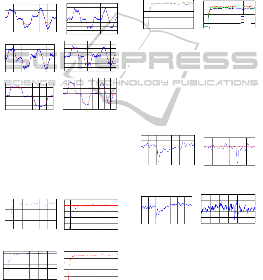
The results obtained (Fig.6) show that both
controllers ensure the trajectories tracking. However,
the SOSM controller demonstrates better behavior in
term of accuracy, settling time and overshoot
comparing with the ISM controller.
Figure 6: Desired Angles (Red) and real Angles outputs
(Blue): (left) ISM, (right) SOSM.
4.3 Altitude Motion
The altitude of the quadrotor will be considered here
for the case of stabilization and robustness to
external disturbances and desired trajectory tracking.
For the stabilization case, the system is
controlled to stabilize the altitude around 40cm as a
set point. The results obtained for both controllers
are shown in the figure 7, 8 and 9.
Figure 7: Altitude stabilization: (left) ISM, (right) SOSM.
Figure 8: Altitude control input (Trust U1): (left) ISM,
(right) SOSM.
The results obtained (fig.7, fig.8, fig.9) show the
stabilization of the altitude of the two controllers
with a superiority of the SOSM controller in relation
to the ISM controller in term of accuracy, settling
time and overshoot.
To verify the robustness of the proposed
approaches for the altitude output; external
disturbance rejection and trajectory tracking tests are
realized.
Figure 9: Propellers speeds (Trust U1): (left) ISM, (right)
SOSM.
The external disturbance realized by adding a
15% of the value of the actual control input U1 to its
next value.
The results obtained (fig.10 and fig.11) show that
even the deviation of the altitude output from its
stable value in the instance of the application of the
disturbance; both controllers damp the effect of the
disturbance in finite time. However and like it seems
clearly the SOSM controller is largely better in term
of the time (4sec) take it to handle the effect of the
disturbance than the ISM (15 sec) controller.
Figure 10: Altitude response with disturbance: (Left) ISM,
(Right) SOSM.
Figure 11: Altitude control input (Trust U1) with
disturbance: (Left) ISM, (Right) SOSM.
In the second robustness test, the system is
submitted to a cycloidal reference trajectory. The
altitude outputs and the corresponding control inputs
U1 of the quadrotor for the both controllers are
given in the figure 12 and 13 respectively.
0 20 40 60 80 100 120
-10
0
10
Time (sec)
Roll (degrees)
0 20 40 60 80
-16
-12
-8
-4
0
4
8
12
16
Times (sec)
Roll(degrees)
0 20 40 60 80 100 120
-10
0
10
Time (sec)
Pitch (degrees)
0 20 40 60 80
-16
-12
-8
-4
0
4
8
12
16
Times (sec)
Roll(degrees)
0 10 20 30 40 50 60 70
-20
0
20
Time (sec)
Yaw (degrees)
0 10 20 30 40 50 60 70 80 90
-30
-20
-10
0
10
20
30
Times (sec)
Yaw(degrees)
5 10 15 20 25 30
0
10
20
30
40
Time (sec)
Altitude z (cm)
0 5 10 15 20
0
10
20
30
40
50
Time(sec)
Altitude z(cm)
5 10 15 20 25 30
0
1
2
3
4
5
6
7
Time (sec)
Trust U1 (N)
0 5 10 15 20
0
1
2
3
4
5
6
7
8
Time(sec)
Trust U1(N)
0 10 20 30
100
120
140
160
180
190
200
Time (sec)
Propellers speeds (rd/s)
0 5 10 15 20
100
120
140
160
180
200
220
Time (sec)
Propellers speeds (rd/s)
rotor1
rotor2
rotor3
rotor4
0 5 10 15 20 25 30 35
20
25
30
35
40
45
50
Time (sec)
Altitude z (cm)
0 5 10 15 20 25 30
20
30
40
50
Time(sec)
Altitude z(cm)
0 5 10 15 20 25 30 35
5.5
6
6.5
7
7.5
Time (sec)
Trust U1(N )
0 5 10 15 20 25 30
6
6.5
7
7.5
8
8.5
Time(sec)
Trust U1(N)
Integral Sliding Mode and Second Order Sliding Mode Attitude and Altitude Tracking of a Quadrotor System - Theory and
Experiment
271
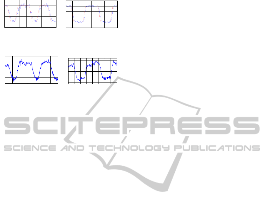
Figure 12: Desired Altitude (Red) and real Altitude (Blue):
(left) ISM, (right) SOSM.
Figure 13: Control inputs: (left) ISM, (right) SOSM.
These results show that both approaches ensure the
tracking of the cycloidal reference trajectory.
However the SOSM approach shows better tracking
performance than the ISM approach.
5 CONCLUSIONS
This paper presents the real time implementation of
two robust controllers on a realized embedded
control system for the stabilization and the tracking
of the quadrotor system. The embedded control
system is based on a dsPIC C. A 3DM-GX1 IMU,
SRF08 sonar and Hall Effect sensors with a little
magnet are used to measure the attitude, the altitude
and the propellers speeds of the quadrotor
respectively. The robust approaches used are the
integral sliding mode with a boundary layer method
and the second order sliding mode. The
experimental results obtained demonstrate the
superiority of the SOSM controller comparing with
ISM controller in term of performance (accuracy,
settling time and overshoot) for the case of
stabilization and tracking and robustness to external
disturbances while cancelling the chattering
phenomena. These results validate theoretical results
and confirm that the SOSM keep the invariance
property in term of performance while reducing the
effect of the chattering which is not the case of the
sliding mode (with a boundary layer method) even
with additional integral term.
REFERENCES
Brisset, P., 2004. Drones civils Perspectives et réalités.
Ecole Nationale de l’Aviation Civile, France.
Bouabdallah, S., 2007. Design and Control of Quadrotors
with Application to Autonomous Flying. PHD thesis,
ASL, EPFL, Lausanne, Suisse.
Bouabdallah, S., Murrieri, P., Siegwart, R., 2004. Design
and control of an indoor micro quadrotor. In
Proceeding of the 2004 IEEE International
Conference on Robotics & Automations New Orleans,
LA.
Escareño J., Salazar-Cruz, S., Lozano, R., 2006.
Embedded control of a four-rotor UAV. In
Proceedings of the 2006 American Control
Conference Minneapolis, Minnesota, USA.
Osmani, H., Bouchoucha, M., Bouri, M., 2010. Design of
an embedded control system for an UAV quadrotor
system. In Proc. of the IFAC 9
th
Portuguese
conference on automatic control (CONTROLO’2010),
Coimbra, Portugal.
Hoffmann, G., M., Huang, H., Waslander, S., L., Tomlin,
C., J., 2007 Quadrotor Helicopter Flight Dynamics and
Control:Theory and Experiment. In AIAA Guidance,
Navigation and Control Conference, Hilton Head,
South Carolina.
Kroo, I., Prinz, F., 2000. The Mesicopter: A miniature
rotorcraft concept –phase ii interim report. Stanford
university, USA.
Derafa, L., Madani, T., Benallegue, A., 2006. Dynamic
modelling and experimental identification of four rotor
helicopter parameters. In IEEE-I CIT, Mumbai, India.
Hanford, S., D., 2005. A small semi-autonomous rotary-
wing unmanned air vehicle. The Pennsylvania State
University The Graduate School, A Thesis in
Aerospace Engineering.
Hamel, T., Mahony, R., Lozano, R., Ostrowski, J., 2002.
Dynamic modelling and configuration stabilization for
an X4-flyer. In Proc. IFAC World Congress.
Barcelona, Spain.
McGilvray, S., J., 2004. Attitude stabilization of a
quadrotor aircraft. A thesis submitted in partial
fulfillment of the requirements for the degree of
Master Science, in control Engineering, Lakhead
University, Thunder Bay, Ontario, Canada.
Bouadi, H., Bouchoucha, M., Tadjine, M., 2007.
Modelling and stabilizing control laws design based
on backstepping for an uav type-quadrotor. In Proc. Of
IAV conference, IFAC, Toulouse France.
Bouchoucha, M., Tadjine, M., Tayebi, A., Müllhaupt, P.,
2008. Bacstepping Based Nonlinear PI for Attitude
Stabilisation of a Four-Rotor Mini-Aircraft: From
Theory to Experiment. In Proc. of IROS/RSJ IEEE,
Nice, France.
Waslander, S., L., Hoffmann, G., M., Jang, J., S., Tomlin,
C. J., 2006. Multi-Agent Quadrotor Testbed Control
Design: Integral Sliding Mode vs. Reinforcement
Learning. In Proceedings of IEEE/RSJ International
Conference on Intelligent Robots and Systems,
Edmonton, Alberta, Canada.
Bouabdallah, S., Siegwart, R., 2005. Backstepping and
Sliding Mode Techniques Applied to an Indoor Micro
Quadrotor. In Proc. of the 2005 IEEE, International
Conference on Robotics and Automation, Barcelona,
Spain.
0 20 40 60 80 100 120 140
0
10
20
30
40
50
Time (sec)
Trust U1 (N)
0 20 40 60 80 100 120 140 160
0
10
20
30
40
50
Time (sec)
Altitude z (cm)
0 20 40 60 80 100 120 140
5.5
6
6.5
7
7.5
Time (sec)
Trust U1(N)
0 20 40 60 80 100 120 140 160
5.5
6
6.5
7
7.5
Time (sec)
Trust U1(N)
ICINCO 2012 - 9th International Conference on Informatics in Control, Automation and Robotics
272

Bouchoucha, M., Seghour, S., Tadjine, M., 2011. Classical
and Second Order Sliding Mode Control Solution to
an Attitude Stabilization of a Four Rotors Helicopter:
from Theory to Experiment. In International
Conference on Mechatronics (ICM 2011), Istanbul,
Turkey.
Seghour, S., Bouchoucha, M., Osmani, H., 2011. From
Integral Backstepping to Integral Sliding Mode
Attitude Stabilization of a Quadrotor System: Real
Time Implementation on an Embedded Control
System Based on a dsPIC µC. In International
Conference on Mechatronics (ICM 2011), Istanbul,
Turkey.
Tayebi, A., Gilvray, S., 2004. Attitude stabilization of a
four-rotor aerial robot. In 43rd IEEE Conference on
Decision and Control, pages 1216 – 1221, Atlantis,
Bahamas.
Boudane, A., Kamel, A., 2011. Commande d’un
Quadrotor basée sur la fusion de donnée d’une
centrale inertielle et d’un système de vision. Projet de
fin d’étude d’ingénieur, Ecole Militaire Polytechnique,
Algiers, Algeria.
Skjetne, R., Fossen, T., I., 2004. On Integral Control in
Backstepping Analysis of Different Techniques. In
Proceeding of the 2004 American Control Conference,
Boston, Massachusetts, USA.
Utkin, V., 1978. Sliding Modes and Their Application in
Variable Structure Systems. Mir, Moscow, Nauka.
Slotine, J. J. E., 1985. The robust control of robot
manipulators. Int . J. Robotics. Res. Vol 4, 10.2, pp 49-
64.
Levant, A., 1997. Higher order sliding: collection of
design tools. In Proceedings of the 4
th
European
Control Conference, Bruxelles, Belgique.
Emelyanov, S., V., Korovin, S., V., Levantovsky, L., V.,
1986. Higher Order Sliding Modes in the Binary
Control System. Soviet Physics, Vol. 31, No 4, pp.
291-293.
Emelyanov, S., V., Korovin, S., V., Levant, A., 1996.
High order sliding mode in control systems.
Computational mathematics and modelling, Vol. 29,
No. 3, pp. 294-318.
Fridman, L., Levant, A., 1996. Sliding modes of higher
order as a natural phenomenon in control theory. F.
Garofalo, L. Glielmo (Eds). Robust Control via
Variable Structure and Lyapunov Techniques, Lecture
Notes in Control and Information Sciences 217,
Sringer Verlag, pp. 107-133.
Nollet, F., Floquet, T., Perruquetti, W., 2008. Observer-
based second order sliding mode control laws for
stepper motors. Control Engineering Practice, Vol. 16,
No. 4, pp. 429-443.
Integral Sliding Mode and Second Order Sliding Mode Attitude and Altitude Tracking of a Quadrotor System - Theory and
Experiment
273
