
Kinematic Analysis of Lower Mobility Cooperative Arms by Screw
Theory
Philip Long, Wisama Khalil and St´ephane Caro
Institut de Recherche en Communications et Cybern´etique de Nantes, UMR CNRS n
◦
6597
´
Ecole Centrale de Nantes, 1 Rue de la No¨e, 44321 Nantes, France
Keywords:
Cooperative Manipulators, Humanoid Robots, Screw Theory.
Abstract:
This paper studies the kinematic modeling and analysis of a system with two cooperative manipulators, work-
ing together on a common task. The task is defined as the transportation of an object in space. The cooperative
system is the dual armed humanoid Nao robot, where the serial architecture of each arm has five degrees of
freedom. The mobility of the closed loop system is analyzed and the nature of the possible motion explored.
The serial singular configurations of the system are considered. Furthermore the parallel singularities of the
closed loop system associated with each actuation scheme are analyzed.
1 INTRODUCTION
The capability of dual independent arms when pro-
cessing parts reduces the need for custom fixtures and
permits the use of a simpler end effector. The system
can then execute sophisticated tasks that may be diffi-
cult for a single arm system. For example, rather than
using a large serial robot a cooperative system dis-
tributes a heavy load among several smaller robots.
Similarly if the object is of an unwieldy, non-rigid
or awkward composition, the single arm robot may
struggle to manipulate it.
By using a cooperative system of two or more ma-
nipulators, both the location and the internal forces
of the object can be controlled. The two principal
approaches that avail of force sensors on the robot
are: hybrid position/force control (Uchiyama and
Dauchez, 1988) and impedance control (Sadati and
Ghaffarkhah, 2008), (Caccavale et al., 2008).
Another approach is to formulate kinematic rela-
tions that create a task space describing the multi-arm
system while grasping an object. The main meth-
ods are known as Symmetric formulation (Uchiyama
and Dauchez, 1988) and Task orientated formulation
(Chiacchio et al., 1996; Caccavale et al., 2000). Both
create a cooperative task space of velocity variables,
describing the object motion in space and the relative
motion between the end effectors (i.e forces applied
on object). On the other hand, the system can also be
viewed as a redundantly actuated parallel manipula-
tor. In this case kinematic constraint equations are de-
rived that establish a relationship between the chosen
independent and dependent joint variables (Yeo et al.,
1999; Liu et al., 1999; Cheng et al., 2003;
¨
Ozkan and
¨
Ozg¨oren, 2001). The dependent joint variables adopt
values that ensure loop closure at each instant.
Most of the preceding work has been carried out
with dual arm systems, where both arms are either
of 3-DOF or 6-DOF spatial composition. Thus away
from singularities, the grasped object has a mobility
of 3 or 6 respectively. On the other hand the study
of lower mobility cooperative manipulators has been
limited. In (Yeo et al., 1999) the cooperation be-
tween a 5-DOF and 4-DOF robot is used in conjunc-
tion with a passive joint in order to execute a 4-DOF
position/force task. In (Zielinski and Szynkiewicz,
1996) admissible path planning for two 5-DOF robots
is explored. In (Bicchi et al., 1995) a generalized
method based on the Jacobian matrix of each arm,
and their constraint relations with the object, is for-
mulated. Analysis of these matrices permits the cal-
culation of the mobility and possible first order differ-
ential motions of general multiple limb robots.
Lower mobility systems suffer from three types of
singularities, limb (serial) singularities, actuation and
constraint (parallel) singularities (Amine et al., 2011).
In (Liu et al., 1999) the presence of parallel singu-
larities of a cooperative system with passive joints is
explored. The issue of a valid selection of actuators
is addressed in (
¨
Ozkan and
¨
Ozg¨oren, 2001). In both
cases an analysis of the Jacobian matrix is carried out.
Conversely screw theory can be used to locate and un-
280
Long P., Khalil W. and Caro S..
Kinematic Analysis of Lower Mobility Cooperative Arms by Screw Theory.
DOI: 10.5220/0004039202800285
In Proceedings of the 9th International Conference on Informatics in Control, Automation and Robotics (ICINCO-2012), pages 280-285
ISBN: 978-989-8565-22-8
Copyright
c
2012 SCITEPRESS (Science and Technology Publications, Lda.)

derstand parallel singularities in closed chain mecha-
nisms (Zlatanov et al., 2002).
In this paper the cooperative system, defined by
the two arms of Aldebaran NAO T14 humanoid robot
and a grasped object, is examined. The system has
been modeled as a closed chain mechanism (Sec-
tions 2 and 3). The originality of this paper lies in the
use of screw theorytechniques to analyze the system’s
mobility, singularities and motion type. The benefit of
this approach is that special configurations such as the
loss of stiffness, loss of DOF etc., can be determined
without the complex derivation of the Jacobian matri-
ces (or their inverses) (Sections 4 and 5).
2 SYSTEM DESCRIPTION
The system is described by the Modified Denavit-
Hartenberg (MDH) notation (Khalil and Kleinfinger,
1986),in Table 1. The right arm consists of joints 1-5
and the left arm consists of joints 6-10. The transfor-
mation matrix
a( j)
T
j
, from frame a( j), the antecedent
of j, to frame j is the 4× 4 matrix given by:
a( j)
T
j
= rot
z
(γ
j
) · trans
z
(b
j
) · rot
x
(α
j
) ·
trans
x
(d
j
) · rot
zj
(θ
j
) · trans
z
(r
j
) (1)
where rot
i
(θ) indicates a rotation of θ radians about
the ith axis and trans
i
(l) a translation of l meters
along the ith axis. It should be noted that γ
j
= b
j
= 0
when x
(a( j))
is perpendicular to z
j
. Once the object is
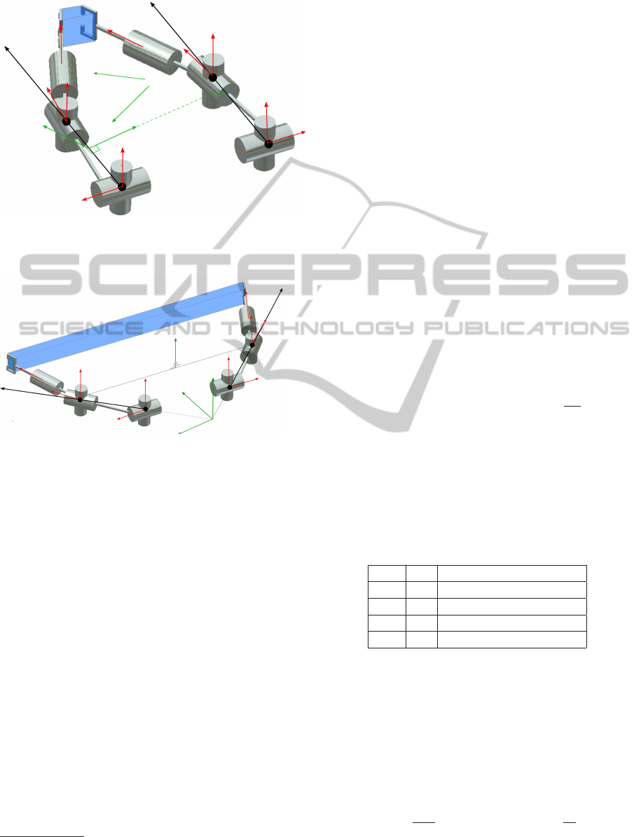
grasped a closed loop is formed. As shown in Fig. 1,
link 5 of the closed chain is composed of link 5, link
10 of the open chain and the object. Frame 10 is fixed
on link 5. We introduce frame 11, which is equiva-
lent to frame 10, but its antecedent is frame 5. The
parameters of frame 11 are defined once the robot has
grasped the object. The system has, in this case, only
nine bodies. Hence joint 10 is denoted as the cut joint.
0
Chain 1
Chain 2
LINK 5
Figure 1: Closed Loop Formulation.
Table 1: MDH Parameters of the closed loop chain.
j a( j) γ b d α θ r
1 0 0 b
1
0 −
π
2
θ
1
-r
1
2 1 0 0 0
π
2
θ
2
0
3 2 0 0 -d
3
π
2
θ
3
r
3
4 3 0 0 0
−π
2
θ
4
0
5 4 0 0 0
π
2
θ
5
r
5
6 0 0 b
1
0
−π
2
θ
6
r
1
7 6 0 0 0
π
2
θ
7
0
8 7 0 0 d
3
π
2
θ
8
r
3
9 8 0 0 0
−π
2
θ
9
0
10 9 0 0 0
π
2
θ
10
r
5
11 5 γ
11
b
11
d
11
α
11
θ
11
r
11
3 KINEMATIC CONSTRAINTS
The location and velocity of the cut joint frame must
be equivalent when calculated via either chain. This
ensures a constant object grasp throughout the trajec-
tory. In the closed loop formulation, joints are des-
ignated either as actuated or passive. q
a
contains the
joint variables that are actuated, q
p
contains the pas-
sive joint variables and q
c
contains the joints that are
cut. The passive and cut joint variables can be ob-
tained in terms of the active joint variables using the
following geometric constraint equations:
0
T
1
1
T
2
2
T
3
3
T
4
4
T
5
5
T
11
=
0
T
6
6
T
7
7
T
8
8
T
9
9
T
10
(2)
Similarly, the kinematic constraints are given by:
ω
11
v
11
=
ω
10
v
10
(3)
By substituting in the joint velocity vectors:
0
J
11
˙
q
r
=
0
J
10
˙
q
l
(4)
where
˙
q
r
and
˙
q
l
contain the joint velocities of the
right arm and the left arm, respectively.
0
v
j
is the lin-
ear velocity and
0
ω
j
the angular velocity of frame j in
frame 0,
0
J
j
is the 6× 5 kinematic Jacobian matrix of
frame j w.r.t. frame 0. By rearranging the rows and
columns of (4), a relationship is obtained between the
passive joint velocities and the actuated joint veloci-
ties
G
a
G
p
0
G
ac
G
pc
G
c
˙
q
a
˙
q
p
˙
q
c
= 0 (5)
From (5), we obtain:
˙
q
p
= −G
−1
p
G
a
˙
q
a
(6)
˙
q
c
= −G
−1
c
G
ac
− G
pc
G
−1
p
G
a
˙
q
a
(7)
KinematicAnalysisofLowerMobilityCooperativeArmsbyScrewTheory
281

The mobility from section 4 is found to be equal
to 4, hence the dimension of G
a
is 5× 4 , G
p
is 5× 5
,G
c
is a scalar (4, 5, 1 being the number of active,
passive and cut joints respectively). G
p
degenerates at
configurations corresponding to parallel singularities
as seen in section 5.2.
4 MOBILITY ANALYSIS
The degree of freedom (DOF) of the system, is equal
to the number of independent coordinates required to
define the pose of the end-effector. The DOF can be
obtained by several methods for example Chebychev-
Gr¨ubler-Kutzbach, or Gogu’s Method (Gogu, 2007).
In order to elucidate the motion type, screw theory is
used. In summary, each serial arm has 5-DOF how-
ever once the object is firmly grasped by each arm, a
closed chain is formed and the object DOF becomes
four.
4.1 Screw Theory
4.1.1 Mobility Analysis based on Screw Theory
Screw theory can be used to analyze the instantaneous
motions of complex mechanisms (Hunt, 1978; Ball,
1900). A screw of pitch λ is defined as:
$
λ
=
s
s× r+ λs
(8)
s is the unit vector of the rotational axis of the screw.
r is the vector from any point on the axis to the ori-
gin. A zero-pitch screw and an infinite-pitch screw
are given respectively by:
$
0
=
s
s× r
, $
∞
=
0
3×1
s
(9)
For every screw system, consisting of n linearly inde-
pendentscrews, there exists a reciprocal screw system
of dimension 6− n. Two screws $
1
and $
2
are recip-
rocal if their instantaneous power is zero, namely,
0
3×3
I
3
I
3
0
3×3
$
1
T
$
2
= 0 (10)
The following reciprocity conditions are defined
from (10):
1. $
0
is reciprocal to $
∞
if their axes ⊥;
2. $
∞
is always reciprocal to another $
∞
;
3. Two $
0
are reciprocal if their axes are coplanar;
A zero-pitch twist ε
0
corresponds to a pure rotation
about its axis. An ∞-pitch twist ε
∞
corresponds to a
pure translation along its axis. A zero-pitch wrench
ζ
0
corresponds to a pure force along its axis. An ∞-
pitch wrench ζ
∞
corresponds to a pure moment about
its axis. The twist system T
i
and the wrench system W
i
of a serial kinematic chain i composed of f joints are
given by:
T
i
=
f
⊕
j=1
T
j
, W
i
=
f
\
j=1
W
j
(11)
The twist system T and the wrench system W of a par-
allel kinematic chain composed of m serial chains are
given by:
T =
m
\
i=1
T
i
, W =
m
⊕
i=1
W
i
(12)
A =
f
⊕
j=1
B
j
means A is spanned by vectors B
1··· f
while
A =
f
T
j=1
B
j
means A is intersection of vectors of B
1··· f
Table 1 shows that NAO T14 is composed of five
revolute joints. From (11), the twist systems T
r
and T
l
of its right and left arms are defined as
1
:
T
r
= span(ε
01
, ε
02
, ε
03
, ε
04
, ε
05
) (13)
T
l
= span(ε
06
, ε
07
, ε
08
, ε
09
, ε
010
) (14)
The first two joints of each arm intersect and consti-
tute a universal (U)-joint. The last three joints also
intersect and are equivalent to a spherical (S)-joint.
Since the twist system of each arm is a 5-system,
its reciprocal wrench system is a 1-system. By reci-
procity condition 3, it can be shown that each arm ap-
plies one pure force (a zero-pitch wrench ζ
0i
, i = 1, 2)
to the object along an axis intersecting the U- and S-
joint axes. Thus, the wrench systems of the two arms
are defined as:
W
r
= ζ
01
, W
l
= ζ
02
(15)
From (12), the constraint wrench system applied to
the object is a 2-system given by:
W
c
= W
r
⊕ W
l
= span(ζ
01
, ζ
02
) (16)
The object twist system is reciprocal to W
c
. Thus, it is
a 4-system and the object has four DOF.
4.1.2 Motion Analysis based on Screw Theory
When the constraint forces are parallel, i.e., ζ
01
k ζ
02
,
reciprocity condition 1 states that there are two inde-
pendent ∞-pitch twists, ε
∞1
and ε
∞2
, reciprocal (nor-
mal) to ζ
01
and ζ
02
. Reciprocity condition 3 states
1
r and l stand for right and left.
ICINCO2012-9thInternationalConferenceonInformaticsinControl,AutomationandRobotics
282
s
1
s
2
s
3
s
4
s
5
s
6
s
7
s
8
s
9
s
10
ζ
01
ζ
02
ε
01
ε
02
ε
∞1
ε
∞2
object
Figure 2: Reciprocal twists to parallel constraint forces
(2T2R motion mode).
s
2
s
1
s
4
s
3
s
5
s
7
s
6
s
8
s
9
s
10
ζ
01
ζ
02
ε
∞
ε
01
ε
02
ε
03
object
Figure 3: Reciprocal twists to intersecting constraint forces
(1T3R motion mode).
that there are also two independent zero-pitch twists,
ε
01
and ε
02
, reciprocal (coplanar) to ζ
01
and ζ
02
as
shown in Fig. 2. Therefore, the corresponding motion
mode is 2T2R
2
.
When ζ
01
∦ ζ
02
, reciprocity condition 1 states
there is one ∞-pitch twist ε
∞1
reciprocal (normal) to
both ζ
01
and ζ
02
and condition 3 states there are three
independent zero-pitch twists, ε
01
, ε
02
and ε
03
, re-
ciprocal (coplanar) to both ζ
01
and ζ
02
as shown in
Fig. 3. Consequently, the correspondingmotion mode
is 1T3R.
5 SINGULARITY ANALYSIS
This section deals with the singularity analysis of the
NAO 14 when it firmly grasps an object. Limb sin-
gularities can be characterized by a loss of DOF of
the limb, while a gain of DOF or a lack of stiffness
is known as a parallel singular configuration (Amine
et al., 2011; Amine et al., 2012).
2
T and R stand for Translation and Rotation, respectively.
5.1 Limb Singularities
A limb singularity is similar to the singularity of a
serial manipulator. It occurs for the dual-arm system
when the limb kinematic screw system (twist system)
degenerates. Consequently, the grasped object loses
one or more DOF in such a configuration. From (9)
and (13) the kinematic Jacobian matrix of the right
arm can be written as:
J
r
=
s
1
s
2
s
3
s
4
s
5
s
1
× r
1
s
2
× r
2
s
3
× r
3
s
4
× r
4
s
5
× r
5
(17)
Let the wrist center be the origin of the frame where
vectors r
i
, i = 1, . . . , 5 are expressed. Equation (17)
becomes
J
r
=
s
1
s
2
s
3
s
4
s
5
s
1
× r
1
s
2
× r
2
0
3
0
3
0
3
(18)
The right arm reaches a limb singularity when J
r
is rank deficient. The relations leading to rank de-
ficiency can be examined. Since s
1
⊥ s
2
, s
3
⊥ s
4
and
s
4
⊥ s
5
these degeneracies can be eliminated. Further-
more, the architecture of the arm means the S-joint
cannot lie on s
2
, leaving two singular configurations.
Firstly when s
3
k s
5
obtained at q
4
= 0 ± π , secondly
when s
1
× r
1
= 0
3
obtained at q
2
= atan
−r
3
d
3
.
5.2 Parallel Singularities
The loss of stiffness due to a parallel singularity can
be characterizedby a degeneracyof screw system rep-
resenting the wrenches. Examples are given in Ta-
ble 2 (Hunt, 1978).
Table 2: Linear Dependence of Screws.
No. ζ
λ
Condition
≥ 2 ζ
0
collinear axes
≥ 2 ζ
∞
parallel axes
> 3 ζ
0
intersect the same point
≥ 6 ζ
0
intersect the same line
5.2.1 Constraint Singularities
A constraint singularity occurs when the constraint
wrench system (16) degenerates, i.e., when ζ
01
and
ζ
02
are linearly dependent (condition 1 in Table 2).
The closed loop system reaches such a configuration
when the two S-joint centers lie on s
1
and s
6
, from the
geometric model:
q
2
= atan
−r
3
d
3
and q
7
= atan
r
3
d
3
(19)
KinematicAnalysisofLowerMobilityCooperativeArmsbyScrewTheory
283
From section 5.1 it is noted that when the closed
loop system reaches a constraint singularity, both
arms reach a limb singularity. Four wrenches form-
ing a 3-system as described in Fig. 4 are applied on
the object: the constraint wrenches ζ
01
and ζ
02
and
the wrenches due to the serial singularity of each arm
ζ
0s1
and ζ
0s2
. As a consequence, the object has 3-
DOF in this configuration.
ζ
01
ζ
02
ζ
0s1
ζ
0s2
Figure 4: Constraint singularity of the dual arm system.
5.2.2 Actuation Singularities
In this section a selection criterion is given for suitable
actuated joints. Once an actuator is locked, it imposes
a wrench on the object. The actuator wrench for joint
i is denoted as ζ
a
λj
. This wrench is reciprocal to all
the twists of the arm except the actuator twist itself
and furthermore it should not lie in W
c
. The actuation
wrench system W
a
applied on the object is the span of
actuation wrenches from both arms, namely,
W
a
= span(W
a
r
, W
a
l
) (20)
The constraint wrenches and actuation wrenches of
both arms should form a 6-system. This system is
denoted as the global wrench system and is defined
as:
W = W
c
⊕ W
a
(21)
An actuation singularity occurs when (21) degener-
ates while (16) does not. Since it is possible to ac-
tuate any four of the ten joints there are
10!
4!(10−4)!
= 210 possible actuation schemes. By excluding
non-symmetrical actuation schemes, 110 actuation
schemes remain. It should be noted that since all the
joints in the arm can be actuated, a redundant actua-
tion scheme can decrease the likelihood of actuation
singularities.
Example 1: q
a
= [q
1
q
2
q
6
q
7
]. Since it is generally
preferable to actuate joints close to the base, the case
when the base U-joints are actuated is examined. The
global wrench system is derived:
• A pure force ζ
a
01
k s
2
and intersecting s
3
, s
4
, s
5
is
coplanar to all twists except that generated by q
1
• A pure force ζ
a
02
k s
1
and intersecting s
3
, s
4
, s
5
is
coplanar to all twists except that generated by q
2
• A pure force ζ
a
06
k s
6
and intersecting s
8
, s
9
, s
10
is
coplanar to all twists except that generated by q
6
• A pure force ζ
a
07
, k s
7
and intersecting s
8
, s
9
, s
10
is
coplanar to all twists except that generated by q
7
The global wrench system as illustrated in Fig. 5,
is given by W = span(ζ
01
ζ
02
ζ
a
01
ζ
a
02
ζ
a
06
ζ
a
07
). A line
between point A and point B (the S-Joints centers of
either arm) can be drawn which is intersected by all
constraint forces regardless of the configuration of the
robot. Thus this actuation scheme is not admissible,
for any configuration the global wrench system de-
generates, i.e. rank(W) = 5, rank(W
c
) = 2, rank(W
a
) =
4, resulting in an uncontrollable closed chain mecha-
nism.
s
2
s
1
s
4
s
3
s
5
s
6
s
7
s
8
s
9
s
10
ζ
01
ζ
02
ζ
a
01
k s
2
ζ
a
02
k s
1
ζ
a
06
k s
7
ζ
a
07
k s
6
A
B
Figure 5: Non-admissible actuation scheme.
Example 2: q
a
= [q
1
q
2
q
3
q
7
]. To find the ac-
tuation wrench applied by q
3
, the planes Π
12
, Π
45
spanned by (s
1
, s
2
) and (s
4
, s
5
) respectively, are ex-
amined:
1. if Π
12
∦ Π
45
, there is a pure force ζ
a
03
acting along
the line formed by the two planes
2. if Π
12
k Π
45
, there is a pure moment ζ
a
∞3
acting
around the line normal to both two planes
The global wrench system for case 1 is shown in
Fig.6, W = span(ζ
01
ζ
02
ζ
a
01
ζ
a
02
ζ
a
03
ζ
a
07
). An actuation
singularity occurs when the line ζ
a
03
contains points A
or B. Other singularities can be obtained by observ-
ing when the wrench system formed by two or more
wrenches degenerates(Table 2), for instance when ζ
a
02
and ζ
a
07
become collinear.
6 CONCLUSIONS
This work has presented a study of the NAO robot’s
two arms engaged in a cooperative task. The DOF of
an object, simultaneously grasped by both arms, was
explored. The serial singularities are straightforward,
ICINCO2012-9thInternationalConferenceonInformaticsinControl,AutomationandRobotics
284

s
2
s
1
s
4
s
3
s
5
s
6
s
7
s
8
s
9
s
10
Π
45
Π
12
ζ
01
ζ
02
ζ
a
01
k s
2
ζ
a
02
k s
1
ζ
a
03
ζ
a
07
k s
6
A
B
Figure 6: Admissible actuation scheme.
more interesting is the presence of constraint singu-
larities. The issue of actuation singularities, present
due to dependent joint variables, was investigated.
By considering the wrenches exerted by the actuators,
both an admissible and inadmissible actuation scheme
were shown.
REFERENCES
Amine, S., Caro, S., Wenger, P., and Kanaan, D.
(2011). Singularity analysis of the H4 robot using
Grassmann–Cayley algebra. Robotica, 1(1):1–10.
Amine, S., Tale Masouleh, M., Caro, S., Wenger, P., and
Gosselin, C. (2012). Singularity analysis of 3T2R
parallel mechanisms using Grassmann–Cayley alge-
bra and Grassmann geometry. Mechanism and Ma-
chine Theory.
Ball, S. R. (1900). A Treatiseon the Theory of Screws. Cam-
bridge Univ Pr.
Bicchi, A., Melchiorri, C., and Balluchi, D. (1995). On the
mobility and manipulability of general multiple limb
robots. Robotics and Automation, IEEE Transactions
on, 11(2):215–228.
Caccavale, F., Chiacchio, P., and Chiaverini, S. (2000).
Task-space regulation of cooperative manipulators.
Automatica, 36(6):879–887.
Caccavale, F., Chiacchio, P., Marino, A., and Villani, L.
(2008). Six-DOF impedance control of dual-arm co-
operative manipulators. Mechatronics, IEEE/ASME
Transactions on, 13(5):576–586.
Cheng, H., Yiu, Y.-k., Member, S., and Li, Z. (2003). Dy-
namics and control of redundantly actuated parallel
manipulators. IEEE/ASME Transactions on Mecha-
tronics, 8(4):483–491.
Chiacchio, P., Chiaverini, S., and Siciliano, B. (1996). Di-
rect and inverse kinematics for coordinated motion
tasks of a two-manipulator system. Journal of Dy-
namic Systems, Measurement, and Control, 118:691.
Gogu, G. (2007). Structural Synthesis of Parallel Robots:
Part 1: Methodology. Springer Verlag.
Hunt, K. (1978). Kinematic geometry of mechanisms. Cam-
bridge Univ Press.
Khalil, W. and Kleinfinger, J. (1986). A new geometric no-
tation for open and closed-loop robots. In Robotics
and Automation. Proceedings. 1986 IEEE Interna-
tional Conference on, volume 3, pages 1174–1179.
IEEE.
Liu, Y., Xu, Y., and Bergerman, M. (1999). Cooper-
ation control of multiple manipulators with passive
joints. IEEE Transactions on Robotics and Automa-
tion, 15(2):258–267.
¨
Ozkan, B. and
¨
Ozg¨oren, M. (2001). Invalid joint ar-
rangements and actuator related singular configura-
tions of a system of two cooperating scara manipu-
lators. Mechatronics, 11(4):491–507.
Sadati, N. and Ghaffarkhah, A. (2008). Decentral-
ized impedance control of nonredundant multi-
manipulator systems. In Networking, Sensing and
Control, 2008. ICNSC 2008. IEEE International Con-
ference on, pages 206–211.
Uchiyama, M. and Dauchez, P. (1988). A symmetric hybrid
position/force control scheme for the coordination of
two robots. In 1988 IEEE International Conference
on Robotics and Automation, Philadelphia, PA, pages
350–356.
Yeo, H.-J., Suh, I. H., Yi, B.-J., and Oh, S.-R. (1999). A sin-
gle closed-loop kinematic chain approach for a hybrid
control of two cooperating arms with a passive joint:
an application to sawing task. IEEE Transactions on
Robotics and Automation, 15(1):141–151.
Zielinski, C. and Szynkiewicz, W. (1996). Control of two
5 dof robots manipulating a rigid object. In Industrial
Electronics, 1996. ISIE’96., Proceedings of the IEEE
International Symposium on, volume 2, pages 979–
984. IEEE.
Zlatanov, D., Bonev, I., and Gosselin, C. (2002). Constraint
singularities of parallel mechanisms. In Robotics and
Automation, 2002. Proceedings. ICRA’02. IEEE In-
ternational Conference on, volume 1, pages 496–502.
IEEE.
KinematicAnalysisofLowerMobilityCooperativeArmsbyScrewTheory
285
