
Broken Bar Fault Detection based on Set Membership Identification for
Three Phase Induction Motors
Mohammed Obaid Mustafa
1
, George Nikolakopoulos
1
, Thomas Gustafsson
1
and Basil M. Saied
2
1
Department of Computer Science, Electrical and Space Engineering, Division of Systems and Interaction,
Lule˚a University of Technology, Lule˚a, Sweden
2
Department of Electrical Engineering, University of Mosul, Mosul, Iraq
Keywords:
Three Phase Induction Motor, Fault Detection, Set Membership Identification.
Abstract:
This article presents a fault detection scheme for the case of a broken bar occurrence in a three phase induction
motor. The proposed scheme relies on Set Membership Identification (SMI) and novel proposed boundary
violation rules for the identified motor’s parameters. The model of the three phase induction motor is being
transformed into an equivalent two phase model, described in the q −d space, for both the normal and the
faulty case. By the utilization of the SMI technique, the simplified equivalent model of the induction motor is
being identified during the steady state operation (non–fault case), while at the same time safety bounds for the
identified variables are being provided, based on an a priori defined corrupting additive noise. On the event of
a fault, specific fault detection conditions are being proposed that can capture the specific type of a broken bar
fault. The proposed conditions depend on: a) abnormal parameter jumps, and b) rapid changes in the volume
of the bounding uncertainty, which is being formulated either by ellipsoids or orthotopes. Detailed analysis of
the proposed approach as also extended simulation results are being presented that prove the efficiency of the
proposed scheme.
NOMENCLATURE
V
sa
, V
sb
, V
sc
: Stator’s three phase voltages (V)
V
ra
, V
rb
, V
rc
: Rotor’s three phase voltages (V)
i
ra
, i
rb
, i
rc
: Rotor’s three phase currents (A)
i
sa
, i
sb
, i
sc
: Stator’s three phase currents (A)
r
s
, r
r
: Resistance of stator’s and rotor’s wind-
ing (Ohm)
L
ss
, L
rr
: Stator’s and rotor’s self–induct-
ances (Henry)
L
s
, L
r
: Stator’s and rotor’s self inductance (Henry)
L
m
: Mutual inductance (Henry)
ω
r
: Rotor’s angular speed (rad/sec)
ω
m
: Rotor’s speed (mechanical) (rad/sec)
ω
s
: Supply angular frequency (rad/sec)
P : No. of poles pairs
J : Moment of inertia (Kg·m
2
)
T
L
: Load torque (Nm)
T
e
: Electromagnetic torque (Nm)
q : Quadrature axis frame
d : Direct axis frame
s : Stator quantities
r : Stator quantities
Ψ
s
, Ψ
r
: Stator’s and Rotor’s fluxes (Weber)
θ : Angular position in the frame of motor (Deg)
θ
r
: Angle between rotor’s phase axis and stator’s
phase axis
β : Angle between rotor’s phase axis and stator’s
phase axis
N
b
: Numbers of machine rotor bars
1 INTRODUCTION
The three phase induction motor is one of the most
important types of motors that are commonly being
found in many industrial applications, mainly due to
their efficiency and reliability (Chen and Zivanovic,
2009), due to the fact that these motors are operating
in difficult working environments with many factors
that degrade their performance such as: dust, tem-
perature level, humidity, continuous operation, and
heavy loads, internal faults frequently occur.
The most common faults that could be appeared in
the rotor and the stator of an induction motor are: a)
short circuit stator winding (Nandi and Toliyat, 2005),
b) broken rotor bars (Santos and Lubiny, 2010), c)
bearing failures, and d) dynamic or static air gab ir-
224
Obaid Mustafa M., Nikolakopoulos G., Gustafsson T. and M. Saied B..
Broken Bar Fault Detection based on Set Membership Identification for Three Phase Induction Motors.
DOI: 10.5220/0004040202240231
In Proceedings of the 9th International Conference on Informatics in Control, Automation and Robotics (ICINCO-2012), pages 224-231
ISBN: 978-989-8565-21-1
Copyright
c
2012 SCITEPRESS (Science and Technology Publications, Lda.)

regularities (Nandi and Toliyat, 2005). From all these
types of faults, the broken bar faults comprise around
(5-10)% of all the reported motor faults, while it is
necessary to detect this type of fault, as soon as possi-
ble as these type of faults can add serious motor dam-
age if not detected on time .
In general for detecting the mechanical or elec-
trical faults in a three phase induction motor mul-
tiple methods have been proposed, which can be
categorized in direct and indirect methods. Direct
methods base their operation on spectral analysis of
stator currents, stator voltages, and electromagnetic
torque (Bachi et al., 2006), with the focus to be on
detecting spectrum lines at certain frequencies using
classical methods like Fouriers analysis and are quite
simple to be implemented. A significant drawback
of these methods is the fact that these are best suited
for fixed speed applications, while in industrial appli-
cations under varying speed and with a direct power
supply, these methods are not well adapted due to the
fact that the involved electrical signals are not station-
ary. Indirect methods base their operation on identifi-
cation or prediction techniques and multiple identifi-
cation schemes for fault detection and fault diagnosis
have been appeared in the literature.
In parallel to these indirect fault detec-
tion schemes, Set Membership Identification
(SMI) (Deller, 1989; Deller et al., 1993) has received
a growing attention in the past years as a quite
important technique for system identification with
uncertainty bounds. The main novelty of this article
stems from the adaptation of the SMI approach to
the problem of fault detection and more specifically
to the problem of detecting broken rotor bar fault for
an induction motor. To the author’s best knowledge
this is the first time that such an approach is being
reported in the scientific literature. The extension
of this scheme to other types of faults can support
a general fault detection framework, where fault
diagnosis could be also performed in parallel with
the fault detection scheme. Based on the proposed
approach, the three phase model of the induction
motor is being transformed to an equivalent two
phase model for the healthy and the faulty case,
and the safety intervals for the online SMI for the
identified parameters, are establishing a robust fault
detection scheme that could be directly transferred to
real–life implementations.
The rest of the article is being structured as it fol-
lows. In Section 2 the model derivation and simplifi-
cation, for the healthy and the faulty cases are being
derived. In Section 3 the SMI scheme is being pre-
sented, followed by the proposed fault detection con-
ditioning framework in Section 4. Section 5 contains
multiple simulation results that prove the efficacy of
the proposed methodology, while the conclusions are
drawn in the last Section 6.
2 INDUCTION MOTOR
MODELING
2.1 Healthy Case
In general an induction motor can be modeled as
a three phase model or as an equivalent quadrature
phase model, while the voltage balance equations for
the case of three phases can be formulated as (Vas,
1992):
V = p ψ + R i
where
V = [V
sa
V
sb
V
sc
V
ra
V
rb
V
rc
]
T
ψ = [ψ
sa
ψ
sb
ψ
sc
ψ
ra
ψ
rb
ψ
rc
]
T
i = [i
sa
i
sb
i
sc
i
ra
i
rb
i
rc
]
T
R = diag
r
s
r
s
r
s
r
r
r
r
r
r
and r
sa
= r
sb
= r
sc
and r
ra
= r
rb
= r
rc
in the balance
case of motor, the operator p is equal to d/dt and the
equations of three phase input voltages are:
V
sa
= V
m
sin(ω
s
t)
V
sb
= V
m
sin(ω
s
t −2π/3) (1)
V
sc
= V
m
sin(ω
s
t −4π/3)
and the relation between the phase linkages and the
phase currents is provided by:
ψ = L i (2)
or
L pi = V−R i
In this formulation the values of the inductance
matrix L depend on the rotor’s electrical angle and
the type of the utilized model (Chen and Zivanovic,
2009). For simplifying the three phase model,
the equivalent two phase model will be extracted
that has been converted to the q − d coordination
frame (Sandhu and Pahwa, 2009). For predicting the
mechanical and electrical behavior of the original ma-
chine correctly, the original abc variables F
abc
should
be transformed into the corresponding d −q variables
F
qdo
and this is being carried out through Park’s trans-
form as it follows (Lee et al., 1985):
F
dqo
= T
qdo
·F
abc
(3)
V
dqo
= T
qdo
·V
abc
(4)
i
dqo
= T
qdo
·i
abc
(5)
BrokenBarFaultDetectionbasedonSetMembershipIdentificationforThreePhaseInductionMotors
225

where
T
dqo
=
2
3
cosθ cosθ
1
cosθ
2
sinθ sinθ
1
sinθ
2
1/2 1/2 1/2
(6)
and
V
dqo
= [v
q
v
d
v
0
]
T
(7)
i
dqo
= [i
q
i
d
i
0
]
T
(8)
with θ
1
= θ − 2π/3, θ
2
= θ −4π/3. In the case
that the saturation and the fraction effects are being
neglected, the balance voltage equation of the three
phase induction motor in q −d model are provided
by:
L
qd
pi
sr
qd
= V
sr
qd
−R
qd
i
sr
qd
(9)
and the pi
sr
qd
can be calculated as:
pi
sr
qd
= −L
−1
qd
R
qd
i
sr
qd
+ L
−1
qd
V
sr
qd
(10)
where
V
sr
qd
= [v
qs
v
ds
v
qr
v
dr
]
T
(11)
i
sr
qd
= [i
qs
i
ds
i
qr
i
dr
]
T
(12)
L
qd
=
L
s
0 L
m
0
0 L
s
0 L
m
L
m
0 L
r
0
0 L
m
0 L
r
(13)
and
R
qd
=
r
s
0 0 0
0 r
s
0 0
0 −ω
r
/ω
s
L
m
rr −ω
s
/ω
s
L
r
ω
r
/ω
s
L
m
0 ω
r
/ω
s
L
r
rr
(14)
After these formulations, equation (10) can be re–
written in a state space form as:
di
qs
dt
di
ds
dt
di
qr
dt
di
dr
dt
= A
i
qs
i
ds
i
qr
i
dr
+ B
V
qs
V
ds
0
0
(15)
where:
A = −R
qd
L
qd
−1
(16)
B = L
qd
−1
(17)
and with the A and B matrices defined as:
A =
1
δ
−L
r
r
s
0 L
m
r
s
0
0 −L
r
r
s
0 L
m
r
s
L
m
r
r
0 −L
s
r
r
w
r
δ
0 L
m
r
r
−w
r
δ −L
s
r
r
(18)
B =
1
δ
L
r
0 −L
m
0
0 L
r
0 −L
m
−L
m
0 Ł
s
0
0 −L
m
0 L
s
(19)
while δ is given as:
δ = L
s
L
r
−Lm
2
(20)
Finally, the resulting equations for the torque and the
mechanical angular speed for the three phase induc-
tion motor are:
T
e
=
3
2
P L
m
[i
qs
i
dr
−i
qr
i
ds
] (21)
dω
m
=
1
J
[T
e
−T
L
]dt (22)
2.2 Broken Bar Model of Three Phase
Induction Motor
The focus of this research effort is on the identifica-
tion of broken bar faults in the rotor of a three phase
induction motor. The reasons of broken bar faults are
thermal, magnetic, residual, dynamic, and mechan-
ical stresses (Nandi and Toliyat, 2005). The event
of a broken rotor bar causes asymmetry of the resis-
tance and inductance in rotor phases, which results
in asymmetry of the rotating electromagnetic field in
the air gap between stator and rotor. Consequently,
this will induce frequency harmonics in the stator cur-
rent. The impact of broken rotor bars can be mod-
eled by unbalancing the rotor resistance, while the
inductance changes are being neglected due to their
insignificance influence compared to the resistance
changes (Bellini et al., 2001; Chen and Zivanovic,
2009), and the stator resistances and inductances stay
unchanged (Chen and Zivanovic, 2009). For simplic-
ity, for a squirrel-cage rotor,the end–ring contribution
is being also neglected.
In the case of such a fault, the modified (faulty)
versions of matrices A
∗
should be utilized. The modi-
fied rotor resistance matrix in the abc reference frame
can be derived as (Chen and Zivanovic, 2009):
r
rf
=
r
r
+ ∆r
ra
0 0
0 r
r
+ ∆r
rb
0
0 0 r
r
+ ∆r
rc
(23)
where ∆r
ra
, ∆r
rb
and ∆r
rc
represent rotor resistance
changes in phase a, b and c, respectivelydueto broken
bar faults. The resistance changes are being derived
based on the assumption that the broken bars are con-
tiguous, neither the end ring resistance nor the magne-
tizing current is taken into account. For the case of n
bb
broken rotor bars, the increment ∆r
ra,b,c
in each phase
is being obtained as (Chen and Zivanovic, 2009; Ku-
mar et al., 2011).
∆r
ra,b,c
= r
r
3n
bb
N
b
−3n
bb
(24)
To simulate broken rotor bar fault, the rotor resistance
matrix needs to be replaced by the modified rotor re-
sistance matrix r
rf
and transformed to q−d reference
ICINCO2012-9thInternationalConferenceonInformaticsinControl,AutomationandRobotics
226

frame, by utilizing the stationary reference frame. For
the cased examined, the rotor resistance changes in
the q −d reference frame as (Chen and Zivanovic,
2009).
∆r
qd0
r f
=
r
r11
r
r12
r
r13
r
r21
r
r22
r
r23
r
r31
r
r32
r
r33
(25)
where
r
r11
=
1
3
(∆r
ra
+ ∆r
rb
+ ∆r
rc
) +
1
6
(2∆r
ra
−∆r
rb
−∆r
rc
)cos(2θ
r
)
+
√
3
6
(∆r
rb
−∆r
rc
)sin(2θ
r
)
r
r12
= −
1
6
(2∆r
ra
−∆r
rb
−∆r
rc
))sin(2θ
r
) +
√
3
6
(∆r
rb
−∆r
rc
)cos(2θ
r
)
r
r13
=
1
3
(2∆r
ra
−∆r
rb
−∆r
rc
))cos(θ
r
) −
√
3
3
(∆r
rb
−∆r
rc
)sin(2θ
r
)
r
r22
=
1
3
(∆r
ra
+ ∆r
rb
+ ∆r
rc
) −
1
6
(2∆r
ra
−∆r
rb
−∆r
rc
)cos(2θ
r
)
+
√
3
6
(∆r
rb
−∆r
rc
)sin(2θ
r
)
r
r23
= −
1
3
(∆r
ra
+ ∆r
rb
+ ∆r
rc
)sin(θ
r
) −
√
3
3
(2∆r
ra
−∆r
rc
)cos(2θ
r
)
r
r33
=
1
3
(∆r
ra
+ ∆r
rb
+ ∆r
rc
)
r
r21
= r
r12
r
r31
=
1
2
r
r13
r
r32
=
1
2
r
r23
and the matrix R
dq
will be also affected, due to the
broken bar fault as:
R
br
∗
=
r
s
0 0 0
0 r
s
0 0
0 −ω
r
/ω
s
L
m
r
rq
−ω
s
/ω
s
L
r
ω
r
/ω
s
L
m
0 ω
r
/ω
s
L
r
r
rd
(26)
with:
r
rq
= r
r
+ r
r11
r
rd
= r
r
+ r
r22
(27)
Therefore the matrices A
∗
, B
∗
in the faulty case will
become:
A
∗
= −R
∗
br
L
−1
(28)
with
A
∗
=
1
δ
−L
r
r
s
0 L
m
r
s
0
0 −L
r
r
s
0 L
m
r
s
L
m
r
rq
0 −L
s
r
rq
w
r
δ
0 L
m
r
rd
−w
r
δ −L
s
r
rd
B
∗
= B (29)
In the sequel the q−d model of the induction motor
is being transformed to a MIMO ARMA system that
can be provided by:
a
aa
˙
i
qs
(t)
˙
i
ds
(t)
˙
i
qr
(t)
˙
i
dr
(t)
=
θ
qs
(t)
θ
ds
(t)
θ
qr
(t)
θ
dr
(t)
T
·
Φ
qs
(t)
Φ
ds
(t)
Φ
qr
(t)
Φ
dr
(t)
T
+
e
qs
(t)
e
ds
(t)
e
qr
(t)
e
dr
(t)
T
(30)
where θ
j
(t) is the parameter vector sets and the
subindex j represents the current set that can be se-
lected as one from: [qs, ds, qr, dr]. Moreover θ
j
(t)
contains the corresponding coefficients of the selected
ARMA model and can be defined in the general case
as:
θ
T
j
(t) = [F
j,1
(t) ... F
n,1
(t), T
j,1
(t), ..., T
m,1
(t)]
T
(31)
Where n and m are the orders of the numerator and de-
nominator for each considered transfer function respec-
tively. The regression vector Φ
j
(t) is being formulated
as:
Φ
T
j
(t) = [−y
j
(t −1), ... ,−y
j
(t −n), ... , u
j
(t + m−n−1), ... , u
j
(t −n)]
In (30) corrupting noise effecting the measurements
is also taken under consideration, while it is assumed
that this noise sequence is bounded by γ
j
∈ ℜ
+
as:
γ
j
||e
j
(t)||
2
≤ 1, ∀t (32)
Finally the parameters in (31) have a direct relation
with the motor’s parameters in both the healthy and
the faulty case. For example, for the case of j = qs
for the faulty case, these parameters can be defined
as:
T
qs,1
=
L
r
δ
, T
qs,2
= −b
1
(a
1
+ a
4
+ a
7
)
T
qs,3
= b
1
(a
2
5
+ a
1
a
4
+ a
1
a
7
−a
2
a
6
+ a
4
a
7
)
T
qs,4
= b
1
(a
1
a
2
5
+ a
1
a
4
a
7
−a
2
a
4
a
6
F
qs,1
= (2a
1
−a
4
+ a
7
)
F
qs,2
= a
2
1
+ a
2
5
+ a
2
b
2
+ 2a
1
a
4
−a
2
a
3
+2a
1
a
7
−a
2
a
6
+ a
4
a
7
F
qs,3
= a
2
1
(a
7
−a
4
) + 2a
1
a
2
5
−a
1
a
2
(a
3
+ a
6
)
+2a
1
a
4
a
7
−a
2
a
3
a
7
−a
2
a
4
a
6
+ a
2
b
2
(a
1
+ a
7
)
F
qs,4
= a
2
1
a
2
5
+ a
2
2
a
3
a
6
−a
1
a
2
(a
3
a
7
+ a
4
a
6
) + a
2
b
2
(a
1
a
7
)
with:
a
1
= −(L
r
r
s
)/δ a
4
= −(L
s
r
rq
)/δ b
1
= L
r
/δ
a
2
= (L
m
r
s
)/δ a
5
= ω
r
b
2
= −L
m
/δ
a
3
= (L
m
r
rq
)/δ a
6
= (L
m
r
rd
)/δ a
7
= −(L
s
r
rd
)/δ
3 SET MEMBERSHIP FAULT
IDENTIFICATION
Set membership identification (SMI) refers to a class
BrokenBarFaultDetectionbasedonSetMembershipIdentificationforThreePhaseInductionMotors
227

of techniques for estimating parameters of linear sys-
tems or signal models under a priori information that
constrains the solutions to certain sets. The objective
of the SMI technique is the determination of the fea-
sible parameter set that contains the nominal parame-
ter vector and is consistent with a linearly parameter-
izable model, the measurement data and the a priori
known bounded noise–error. Due to the complexity
in computing the feasible parameter set, the major-
ity of the SMI methods aims at the determination of
a more conveniently computable parametric set that
outer bounds the feasible parameter set (Ljung, 1987;
Deller, 1989).
The SMI technique is based on the Weighted Re-
cursive Least Squares (WRLS) with a forgetting fac-
tor for identifying the
ˆ
θ
j
motor’s parameters and
can be formulated by the following double recur-
sions (Guastafsson, 2001) in the sample instance t and
for the MIMO case j as:
ˆ
θ
j
(t) =
ˆ
θ
j
(t −1) + K
j
(t)(y
j
(t) −Φ
T
j
(t)θ
j
(t −1))
K
j
(t) = P
j
(t −1)Φ
j
(t)(λ+ Φ
T
j
(t)P
j
(t −1)φ
j
(t))
−1
P
j
(t) = (I −K
j
(t) Φ
T
j
(t))P
j
(t −1)/λ
e
j
(t) = y
j
(t) −Φ
T
j
(t)θ
j
(t −1)
G
j
(t) = Φ
T
j
(t)P
j
(t −1)Φ(t)
In the SMI approach the initial bounds γ for the cor-
rupting noise ε
j
(t) are being re–calculated in every it-
eration. This optimization in the uncertainty descrip-
tion is evolving with the time, as the better the knowl-
edge of the parameters is, the smaller these bounds
are. To calculate the optimal value of λ
∗
j
(t) for achiev-
ing convergence, the maximum positive root of the
following equation should be extracted in each itera-
tion:
F
j
(λ
j
) = α
2, j
λ
2
j
+ α
1, j
λ
j
+ α
0, j
α
2, j
= (ℓ + n−1)G
2
j
α
1, j
= (2ℓ + 2n−1+ γ
j
e
2
j
) −ξ
j
γ
j
G
j
)G
j
α
0, j
= (ℓ + n) ∗(1−γ
j
e
2
j
) −ξ
j
G
j
γ
j
ξ
j
(t) = ξ
j
(t −1) +
λ
j
γ
j
−
λ
j
e
j
1−λ
j
G
j
with ℓ = m + 1. For founding the upper and lower
boundary for the identified parameters, the uncer-
tainty bound σ
j
(t), should be computed in every it-
eration. For delivering these bounds, the smallest or-
thotope that bounds the ellipsoidal uncertainty of the
parameter and it is oriented parallel to the parameter
coordinate axes and centered on the centroid of the
ellipsoid is being calculated as:
σ
j
(t) =
q
diag(P
j
(t)) (33)
while the corresponding equation for the ellipsoids
Ω
e
j
(t) and the orthotopes Ω
p
j
(t) can be calculated
as (Deller, 1989):
Ω
e
j
(t) = {θ
j
: (θ
j
(t) −
ˆ
θ
j
(t))
T
C
j
(t)
ξ
j
(t)
)(θ
j
(t) −
ˆ
θ
j
(t)) ≤ 1, j = 1, ...., n+ m}
Ω
p
j
(t) = {θ
j
: (
1
|σ
j
(t)|
)(θ
j
(t) −
ˆ
θ
j
(t)) ≤ 1, j = 1, ...., n+ m}
with the orthotope’s vertices V
n+m+1
j, o
(k), o =
0,.. .,2
n+m+1
−1 are related to the σ
j
parameters as:
V
p
j, o
(k) = θ
j
(t) + [α
∗
j, n+m+1
σ
j, n+m+1
(t), . ..,α
j, 1
σ
j, 1
(t)]
T
where α
∗
j,(·)
=
(
+ when a
j, (·)
= 1
− when a
j, (·)
= 0
, and the co-
variance matrix is denoted as C
j
(t) = P
j
(t)
−1
. The
matrix W(t) =
C
j
(t)
ξ
j
(t)
will represent how far the ellip-
soid extends in each direction from the center of the
ellipsoid
ˆ
θ
j
(t), while the volume ratio of the j ellip-
soid is being calculated by: B
j
(t) = det
−1
(W(t)).
4 FAULT DETECTION
CONDITIONING
In the case of a broken bar fault occurrence, the values
of the identified parameters will be characterized by a
jump and a constant drift from the converged nominal
values of the healthy motor. This jump has a direct
effect on the updated parameter’s bounds, as after the
event of the fault the following calculated uncertainty
bounds will exceed the previous calculated bounds in
the healthy case, while this situation is a direct indi-
cation of a fault occurrence. Based on the proposed
SMI scheme, the following rules for the fault occur-
rence identification will be established as it is being
depicted in Figure 1. In the presented approach it
has been assumed that the SMI scheme is providing
smooth value updates for the identified parameters.
If a t
1
time window is being defined, then after
the convergence of the parameters, small changes
in the identified values should be allowed, while a
significant change might indicate the occurrence of a
fault. For the ad–hoc defined bound B
1
the first fault
detection condition is being formulated as:
[Condition 1] |θ
o
j
(k) −
ˆ
θ
j
(k−t
1
: k)| ≥ B
1
where θ
o
j
(k) denotes the converged identified
parameter and the notation · represents a moving
average time window of length t
1
. Two additional
rules can be defined, that are related with the volumes
of the bounding ellipsoids Ω
e
j
or orthotopes Ω
p
j
. The
aim is to track the corresponding volumes of the
bounding ellipsoid/orthotope and allow only small
ICINCO2012-9thInternationalConferenceonInformaticsinControl,AutomationandRobotics
228
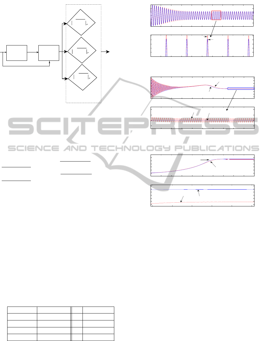
U
Set Membership
Identification
Three Phase
Induction Motor
Y
θ -θ (k-t : k) >B
j
o
^
j
1
1
Ω -Ω (k-t :k) >B
j
,o
^
j
2
2
e
Ω -Ω (k-t :k) >B
j
^
j
3
3
p
e
p
Fault Detection
Conditioning
Fault
Occurrence
,o
Figure 1: Faults detection scheme.
changes, as in the opposite case, this should generate
a fault. By defining two ad–hoc boundaries as B
2
and B
3
and two additional time windows t
2
, t
3
, the
following additional fault detection conditions can be
formulated:
[Condition 2] |Ω
e,o
j
(k) −Ω
e
j
(k−t
2
) : k| ≥ B
2
[Condition 3] |Ω
p,o
j
(k) −Ω
p
j
(k−t
3
: k)| ≥ B
3
Where Ω
e,o
,Ω
p,o
are the converged values and
conditions (2) and (3) are complimentary and
depending on the processing capabilities and the
accuracy that we would like to achieve. In general,
condition (2) is more accurate that condition (3), as
the orthotope is bounding the uncertainty described
by the ellipsoid, but this approach has the drawback
that it is more computational demanding.
5 SIMULATION RESULTS
The suggested scheme for fault detection is being
evaluated on a model of three phase induction motor
having the parameters depicted in Table 1.
Table 1: Induction Motor Parameters.
Pole Numbers 4 r
s
0.0616 per unit
Input Voltage 240V r
r
0.0753 per unit
Frequency 50Hz J 0.00155 Kg.m
L
r
0.019 per unit L
s
0.019 per unit
L
m
0.01833 per unit N
b
28
The first simulation results will focus in present-
ing the effect of one broken bar fault occurrence on
the rotor’s current, torque and angular speed, as it is
1 1.1 1.2 1.3 1.4 1.5 1.6 1.7 1.8 1.9 2
x 10
4
−3
−2
−1
0
1
2
3
I
qr
(Per unit)
1.6 1.61 1.62 1.63 1.64 1.65 1.66 1.67 1.68 1.69 1.7
x 10
4
1.1
1.105
1.11
1.115
1.12
1.125
Time (Sec)
I
qr
(Per unit)
Normal case
Faulty case
Figure 2: The rotor’s currents in the normal and faulty case.
0 0.2 0.4 0.6 0.8 1 1.2 1.4 1.6 1.8 2
x 10
4
−0.5
0
0.5
1
1.5
2
2.5
3
Torque (Per Unit)
1.5 1.55 1.6 1.65 1.7 1.75 1.8 1.85 1.9 1.95 2
x 10
4
0.98
1
1.02
1.04
Time (Sec)
Torque (Per Unit)
Faulty case
Normal case
Faulty case
Normal case
Figure 3: The torque of the motor in the normal and faulty
case.
1.5 1.55 1.6 1.65 1.7 1.75
x 10
4
0.903
0.904
0.905
0.906
0.907
0.908
0.909
Time (Sec)
Wr / Ws
0 0.2 0.4 0.6 0.8 1 1.2 1.4 1.6 1.8 2
x 10
4
−0.2
0
0.2
0.4
0.6
0.8
1
1.2
Wr / Ws
Faulty case
Normal case
Faulty case
Normal case
Figure 4: The rotor angular speed of the motor in the normal
and faulty case.
being presented in Figures (2-4) respectively. For the
rotor’s current, same results have been also obtained
as in Figure (2).
From the obtained results, it can be observed that
the small change in the values of the currents can
be distinguished, where the rotor’s current I
qr
in the
faulty case will be increased from the corresponding
value in the healthy case. In Figures (3 and 4), it is
also depicted that the fault is affecting the steady state
values of the rotor’s torque and speed respectively. In
the case of the motor’s torque oscillations are taking
place, while the amplitude of these oscillations is be-
ing increased with respect to the number of the faulty
broken bars. In the second case, the speed is also been
decreased, while oscillations are also evident.
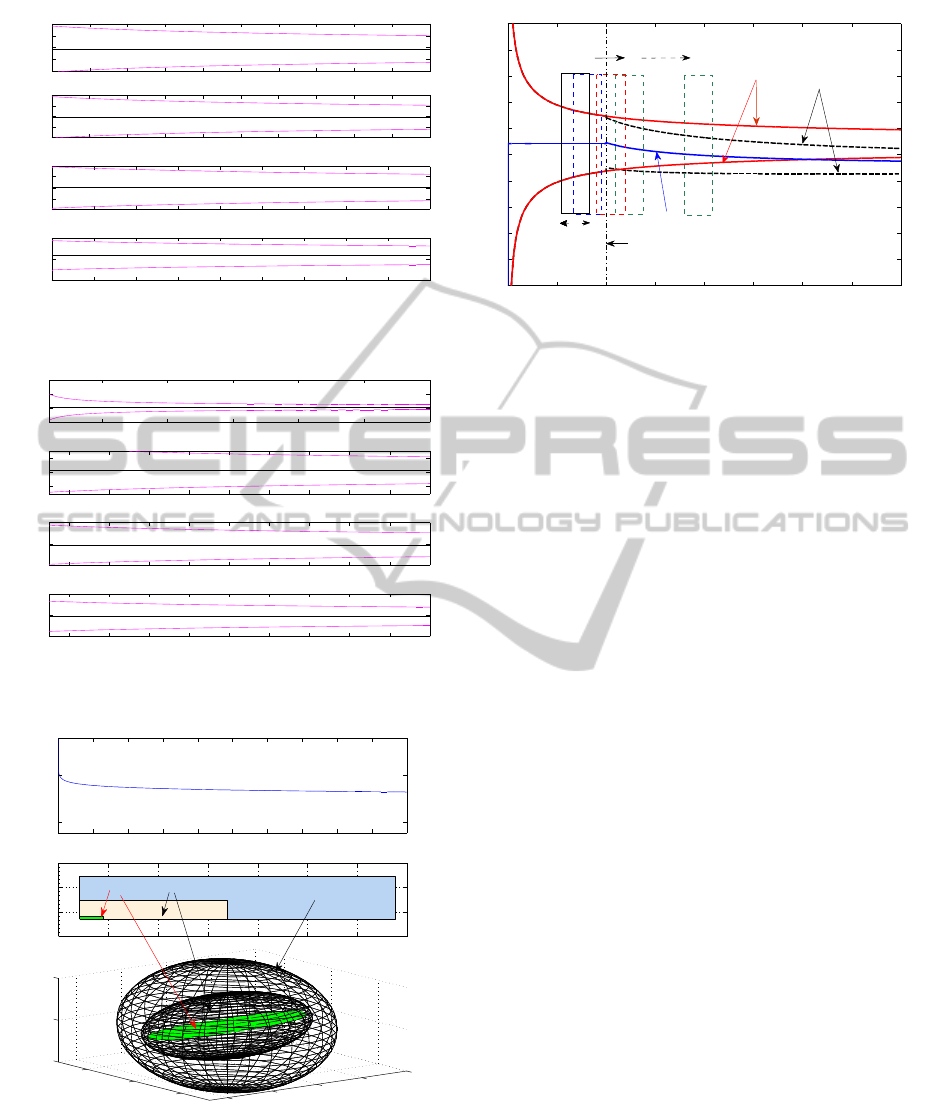
In the sequel, results from applying the proposed
SMI scheme for broken bar fault detection are go-
ing to be presented. Figures (5), and (6) present the
convergence of the SMI identification (with the un-
certainty bounds) of the motor’s parameters in the
BrokenBarFaultDetectionbasedonSetMembershipIdentificationforThreePhaseInductionMotors
229
1 1.2 1.4 1.6 1.8 2 2.2 2.4 2.6 2.8 3
x 10
4
−4
−2
0
2
4
F
qs,1
1 1.2 1.4 1.6 1.8 2 2.2 2.4 2.6 2.8 3
x 10
4
−4
−2
0
2
4
F
qs,2
1.2 1.4 1.6 1.8 2 2.2 2.4 2.6 2.8 3
x 10
4
−0.5
0
0.5
F
qs,3
1.2 1.4 1.6 1.8 2 2.2 2.4 2.6 2.8 3
x 10
4
−0.1
0
0.1
Sample Index
F
qs,4
Figure 5: SMI based identified parameters for F
i
qs
and cor-
responding uncertainty bounds.
0.5 1 1.5 2 2.5 3
x 10
4
8
8.5
9
9.5
T
qs,1
1.2 1.4 1.6 1.8 2 2.2 2.4 2.6 2.8 3
x 10
4
−20
0
20
T
qs,2
1.2 1.4 1.6 1.8 2 2.2 2.4 2.6 2.8 3
x 10
4
−20
0
20
T
qs,3
1.2 1.4 1.6 1.8 2 2.2 2.4 2.6 2.8 3
x 10
4
−10
0
10
Sample Index
T
qs,4
Figure 6: SMI based identified parameters for T
i
qs
and cor-
responding uncertainty bounds.
8.5 8.6 8.7 8.8 8.9 9 9.1 9.2
8.4
8.6
8.8
9
T
qs,1
T
qs,2
0 1 2 3 4 5 6 7 8 9 10
x 10
4
10
−50
10
0
Sample index
Ellipsoid volume ratio
0
5
10
15
20
−100
0
100
−50
0
50
T
qs,3
@ 500 Sample
@ 2500 Sample
@ 99000 Sample
Figure 7: Orthotope and ellipsoid change with sample in-
dex.
healthy case, only for the case of having as input V
qs
and output i
qs
, while similar results have been ob-
tained for the rest of the motor’s parameters, but due
to space limitations, those graphs have been omitted.
0 1 2 3 4 5 6 7 8
x 10
4
8
8.1
8.2
8.3
8.4
8.5
8.6
8.7
8.8
8.9
9
Sample index
T
qs,1
with bounds in normal and faulty case
Moving window
Bounds in faulty case
Bounds in normal case
T
qs,1
D
p1
Fault ocurrence
Figure 8: Convergence of the T
qs,1
parameter and corre-
sponding bounds before and after the occurrence of the
fault.
As it can be observed from these figures the uncer-
tainty bounds are starting from a large value and in
the sequence, as the identification procedure is evolv-
ing and the identified parameters are close to the nom-
inal values, those bounds are being decreased, until it
reach their steady state value. Finally, in Figure (7)
the convergence of the ellipsoid volume and the con-
vergence of the orthotope’s volume is being presented
and the corresponding bound sets of uncertainty are
being presented at different time indexes, where the
evolution of the volume has been highlighted with re-
spect to the sample index.
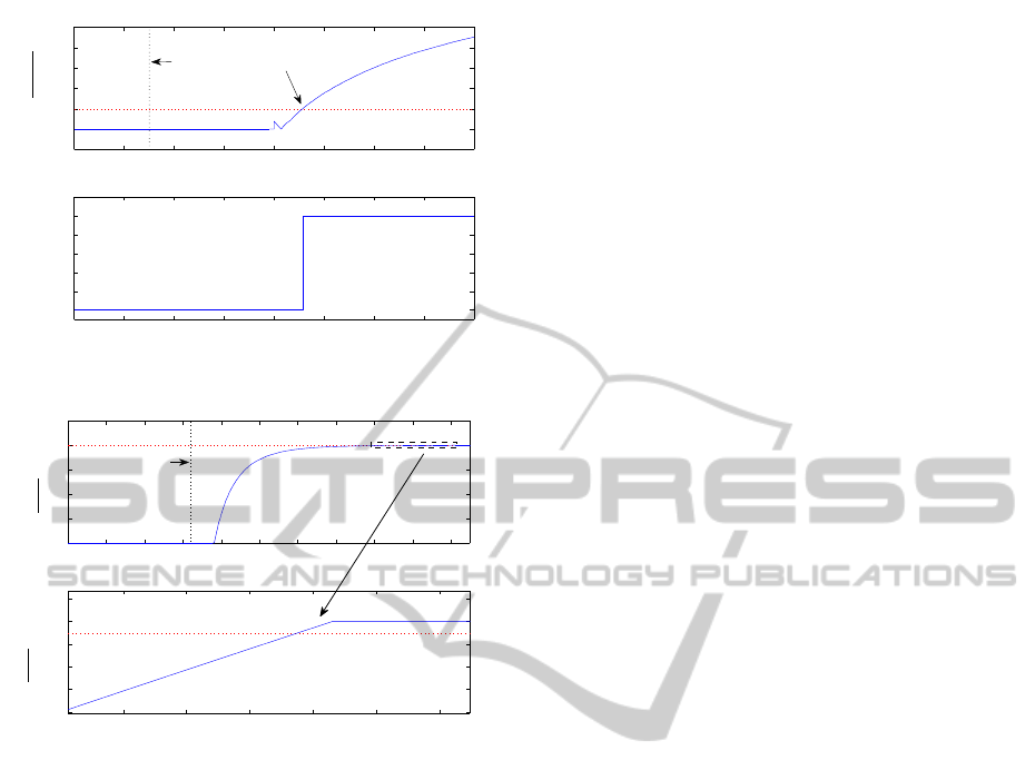
In Figure 8, the case of a fault occurred at 20000
samples (Sampling time T
s
= 0.01) is being presented.
Due to this fault a jump in the identified parameters
is taking place that affects the presented conditions
for fault detection. More specifically, the uncertainty
intervals are changing (due to the drift in the identi-
fied model) and this leads in a bounds violation event,
which indicates the existence of the broken rotor fault.
Similar graphs can also be extracted for all the identi-
fied parameters of the motor and without loosing gen-
erality, in Figure 8, only the results for T
qs,1
are being
presented.
The effectiveness of the identification scheme can
also be examined by inspecting the volume of the
bounding ellipsoid. As it is being displayed in Fig-
ure (7) the ellipsoid volume will be minimized as the
identified model matches the real one. In the even
of a fault, the identified values are being drifted to
small values (resulting from the faulty model repre-
sentation) and thus is why the bounds are being kept
on monotonically being decreased. In the case of a
rotor’s broken bar, the operation of the motor is still
unaffected, and the result due to the fault is a small
parametric drift and this is why a the simple inspec-
tion of the identified parameters in not the only factor
that should be monitored for fault identification, but
ICINCO2012-9thInternationalConferenceonInformaticsinControl,AutomationandRobotics
230
0 0.5 1 1.5 2 2.5 3 3.5 4
x 10
4
−0.01
0
0.01
0.02
0.03
0.04
0.05
Sample Index
|
ˆ
θ
j
(k) −
ˆ
θ
j
(k − t
1
: k)|
0 0.5 1 1.5 2 2.5 3 3.5 4
x 10
4
0
0.2
0.4
0.6
0.8
1
Sample Index
Fault detection
Bound violation
convergance
time
B
1
=0.01
Figure 9: Fault detection after 1
st
condition monitoring.
2.002 2.003 2.004 2.005 2.006 2.007
x 10
4
7.992
7.994
7.996
7.998
8
8.002
x 10
−11
Sample Index
|(Ω(k − t
1
) − Ω(k))|
0 0.2 0.4 0.6 0.8 1 1.2 1.4 1.6 1.8 2
x 10
4
0
0.2
0.4
0.6
0.8
x 10
−10
Sample Index
|(Ω(k − t
1
) − Ω(k))|
B
2
= 0.8e − 10
Convergance time
Figure 10: Fault detection after 2
nd
condition monitor-
ing/condition2.
is should be combined with the second or third condi-
tion for the ellipsoid or the orthotope’s volume. In the
examined case, the occurrence of the fault has caused
a jump on the ellipsoid’s volume convergence, which
was bigger than the a priori defined bound and thus
the algorithm is able to trigger the even of the fault.
The time evolutions of the fault detection con-
ditions are being presented in Figures (9) and (10)
where the convergence time for the identified param-
eters is also being displayed, along with the bound
violation for the conditions (1) and (2).
6 CONCLUSIONS
In this article a fault detection scheme for broken ro-
tor bar fault detection has been presented in the case
of a three phase induction motor. The three phase in-
duction motor has been modeled in the equivalent two
phase motor (q−d) space, while the modeling of the
faulty case has been also formulated. The motor has
been identified by the utilization of the SMI algorithm
that has the merit of identifying both the parameters of
the motor as also providing uncertainty safety bounds
by calculating ellipsoids/orthotopes, which bounds
the systems parameter vector. The obtained results
present the efficiency of the proposed conditions to
capture the event of the fault.
REFERENCES
Bachi, S., Tnani, S., Trigeassou, J., and Champenois,
G. (2006). Diagnosis by parameter estimation of
stator and rotor faults occurring in induction ma-
chines. IEEE Transactions on Industrial Electronics,
53(3):963–973.
Bellini, A., Filippetti, F., Franceschini, G., Tassoni, C., and
Kliman, G. (2001). Quantitative evaluation of induc-
tion motor broken bars by means of electrical signa-
ture analysis. IEEE Transactions on Industry Appli-
cation, 37(5):1248–1255.
Chen, S. and Zivanovic, R. (2009). Modelling and sim-
ulation of stator and rotor fault conditions in induc-
tion machines for testing fault diagnostic techniques.
European Transactions On Electrical Power, 20:611
–629.
Deller, J., Nayeri, M., and Odeh, S. (1993). Least–Square
Identification with Error Bounds for Real–Time Sig-
nal Processing and Control. Proceedings of the IEEE,
81(6):815–849.
Deller, J. R. (1989). Set membership identification in digital
signal processing. IEEE ASSP Magazine, 6(4):4–20.
Guastafsson, F. (Sep.2001). Adaptive Filtering and Change
Detection.
Kumar, S., Prakash, J., and Kumar, S. S. (2011). Detection
of broken rotor bars in induction motor using deriva-
tive free kalman filters. International Conference on
Process Automation, Control and Computing (PACC),
2011, pages 1 – 7.
Lee, R., Pillay, P., and Harley, R. (1985). Dq reference
frames for the simulation of induction motors. Elec-
tric Power Systems Research, 8:15 –26.
Ljung, L. (1987). System Identification Theory For The
User. Prentice–Hall, Englewood Cliffs, NJ.
Nandi, S. and Toliyat, H. (2005). Condition monitoring and
fault diagnosis of electrical machines-a review. IEEE
Transactions on Energy Conversion, 20(4):719–729.
Sandhu, K. and Pahwa, V. (2009). Sumilation study of three
phase induction motor with variation in moment of in-
ertia. ARPN Journal of Enginering and Apllied Sci-
ences, 4(5):72–77.
Santos, P. and Lubiny, T. (2010). A simplified induction
machine model to study rotor broken bar effects and
for detection. European Transactions On Electrical
Power, 20:611.
Vas, P. (1992). Electrical Machines and Drives.
BrokenBarFaultDetectionbasedonSetMembershipIdentificationforThreePhaseInductionMotors
231
