
Improving Stereo Vision Odometry for Mobile Robots
in Outdoor Dynamic Environments
Dan Pojar and Sergiu Nedevschi
Department of Computer Science, Technical University Cluj-Napoca, Cluj-Napoca, Romania
Keywords: Visual Odometry, Stereo Vision, Localization, Mobile Robot, Real-Time.
Abstract: This article presents a method for localization able to provide the pose in 3D using stereo vision. The
method offers a better and inexpensive alternative to classical localization methods such as wheel odometry
or GPS. Using only a calibrated stereo camera, the method integrates both optical flow based motion
computation and SURF features detector for stereo reconstruction and motion computation. Robustness is
obtained by finding correspondences using both feature descriptors and RANSAC inlier selection for the
reconstructed points. Least squares optimization is used to obtain the final computed motion. World scale
pose estimation is obtained by computing successive motion vectors characterized through their orientation
and magnitude. The method involves fast algorithms capable to function at real time frequency. We present
results supporting global consistency, localization performance and speed as well as the robustness of the
approach by testing it in unmodified, real life, very crowded outdoor dynamic environments.
1 INTRODUCTION
Recent trends in mobile robotics deal with a
fundamental requirement of any robot, the
possibility of localizing itself. As robots moved from
a highly deterministic environment the proposed
solutions for localization had to deal with more and
more difficult scenarios.
Solutions that used both custom infrastructure
and expensive sensor configurations exist already.
Wheel odometry is the most commonly encountered
solution that allows easy and cheap localization but
is reliable only for a few tens of meters, at best, due
to accumulated measurement errors.
A different alternative that has previously been
explored but which only recently has been shown to
provide better results relies on using cameras as
sensors. Our paper focuses on the type of approaches
named structure from motion. Different methods can
also use different types of cameras, but most work is
based on monocular or stereo cameras.
Structure from motion methods allow recovering
both scene geometric structure and camera extrinsic
as well as intrinsic parameters from sets of images of
the scene taken from different poses.
2 RELATED WORK
One of the most cited approaches by (Nister, 2006)
presents solutions for both monocular and stereo
setups. The 5 point algorithm or in the case of a
stereo camera, a 3 point perspective method referred
therein is enough to compute the relative pose
change. Other work presented by (Konolige and
Agrawal, 2007) is also based on stereo vision. In this
case, the authors use 3D triangulation from stereo.
A similar approach used among other purposes
for the Boston Dynamics Big Dog robot is given by
(Howard, 2008). Other sensors such as expensive
IMU are used to offer a reference. (Scaramuzza,
2009) presents a solution tested on an
omnidirectional camera that uses only one point to
compute the motion hypothesis for RANSAC outlier
rejection. This is possible because the motion model
is restricted to planar motion. A simplified stereo
motion model which can be directly computed is
presented in (Jeong, 2010). The author uses robot
wheel odometry to correct errors that occur from
stereo based motion computation.
In our previous work (Pojar, 2010) we presented
an approach that simplified to planar motion, similar
to (Scaramuzza, 2009) using a stereo camera.
476
Pojar D. and Nedevschi S..
Improving Stereo Vision Odometry for Mobile Robots in Outdoor Dynamic Environments.
DOI: 10.5220/0004043404760480
In Proceedings of the 9th International Conference on Informatics in Control, Automation and Robotics (ICINCO-2012), pages 476-480
ISBN: 978-989-8565-22-8
Copyright
c
2012 SCITEPRESS (Science and Technology Publications, Lda.)

3 METHOD OVERVIEW
Motion from images is obtained from point
correspondences obtained from consecutive image
pairs from a stereo camera. These result in two
corresponding 3D point vectors.
To compute the rotation a minimum of 3 points
are needed. In a RANSAC procedure multiple such
rotation hypothesis are obtained by random
sampling. In order to obtain the current location the
currently computed vector must be registered with
the previous location.
3.1 Retrieving Correspondences and
the Homography
In order to determine the corresponding projections
of the same point in different images a corner
detector described in (Shi and Tomasi, 1994) as well
as the SURF feature descriptor are used. Their
corresponding pairs in a different image are obtained
with the Lucas-Kanade pyramidal optical flow in the
case of corners. In the case of SURF (Bay and
Tuytelaars 2008) features the feature vector distance
is used to determine matches.
If corresponding pairs are available in both images
then the coordinates, in our case the 3D coordinates
at world scale, can be computed using the disparity
rl
uud
from the following:
d
bf
f
Zpv
f
Zpu
zyx
yl
xl
,
)(
,
)(
),,(
(1)
where
b
is the baseline and
f
is the focal length.
A pair of vectors denoting the coordinates of a
point in 3D space
p
and
'p
can be related through a
homography consisting of a rotation and a
translation:
1101
' pTRp
(2)
where
T
zyxp ),,(
and
T
zyxp )',','('
the 3D
coordinates of the points and
R
is a 3x3 matrix
obtained from the three Euler angles
,
,
and
T
is a 3x1 vector that contains the translation on
each axis.
3.2 Computing Relative Motion
Motion is computed from change in orientation and
position between two consecutive poses. If the
magnitude of the vectors is up to scale then the
translation can be neglected and the homography
becomes a rotation.
The correspondences allow computing the
rotation matrix
R
from:
1
)
ˆˆ
(
ˆ
'
ˆ
TT
PPPPR
(3)
Considering that the rotation matrix is the result
by multiplying the corresponding rotation matrices
of each axis then the angles can be obtained directly:
)/(2tan
1121
rra
,
)/(2tan
2
33
2
3231
rrra
,
)/(2tan
3332
rra
.
3.3 Robust Inlier Selection and
Refinement
Many of motion hypotheses are wrong dues to
incorrect correspondences in the tracking stage.
In order to cope with outliers two stages of
RANSAC are applied to the images. It is debated in
(Hartley and Zisserman, 2003) how many samples
should be selected in order to encounter at least one
inlier, considering the dimensionality of the sample
and the outlier ratio.
Each hypothesis is applied to all the points in the
previous pair of stereo frames and scoring is based
on measuring the projection of the hypothesized
points in the current image. The projection is
computed with the projection matrix in the current
left image:
PKp
(4)
where
RPP
and
K
is the pinhole camera
projection matrix. The score is computed by
summing the errors between the tracked and
hypothesized image points. Inliers are selected by
comparing the distance of the hypothesized
projections with a threshold.
After selecting the inlaying points a solution for
the rotation is computed via a least squares
minimization algorithm.
))
ˆ
'
ˆ
min((,,
2
PPR
(5)
The preffered solution for minimization is the
Levenberg-Marquardt algorithm.
3.4 Global Pose Computation
The rotation matrix provides a direction of motion.
In order to determine the motion magnitude we
consider the world scale coordinates of the points
selected as inliers. Excluding rotation, translation is
a first order linear operation and is independent for
Improving Stereo Vision Odometry for Mobile Robots in Outdoor Dynamic Environments
477
each axis so the optimal solution is unique and is the
centroid of the differences given by:
,
,
.
The magnitude of motion is the magnitude of the
variation vector on each axis:
(6)
The final step is computing a pose in the world
coordinate system. Initially the camera is considered
to be placed at the origin of the world coordinate
system. At each step the current pose is registered
relative to the pose at the previous step. Change in
orientation can be registered directly by summing
the angular variations:
(7)
The position is registered based on the new
orientation and on the motion magnitude:
(8)
4 EXPERIMENTS AND RESULTS
We present in the paper results obtained with a Tyzx
DeepSea stereo camera. The camera was rigidly
mounted on a Pioneer2 AT mobile robot. The
algorithm is tested in scenarios, outdoor and indoor.
The test scenarios are real life environments without
any modifications. In the outdoor case the area
where the test was performed is a public space, a
very dynamic environment.
Implementation was done using OpenCV
(Bradski, 2008), which provides very convenient
feature tracking implementations, and Boost Library.
In all scenarios the mobile robot was driven
remotely on a path in different environments. The
chosen paths were quite complex, containing loops
in order to test global consistency and most times
followed the surrounding buildings layout.
The first test scenario was an outdoor and
dynamic environment. Situations where moving
obstacles clutter the image can have serious outcome
on motion recovery. The algorithm was able to
recover the travelled path with good accuracy.
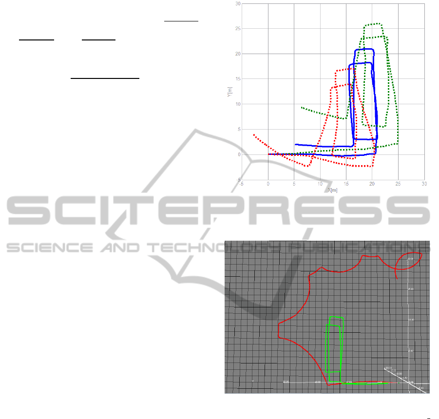
In Figure 1 we present the results of the
algorithms when only one feature descriptor is used.
A more robust estimation can be performed
Figure 1: Comparison of the computed paths in the case of
each descriptor: Corners (red), SURF (green),
Corners+SURF (blue).
Figure 2: Wheel encoder odometry (red) compared to
visual odometry (green) represented on a metric grid of
1x1m.
when both types of descriptors are used.
In Fig 2 the path computed by the visual
odometry algorithm is compared to the path
computed by the wheel encoder odometry provided
by the Pioneer 2AT robot. Visual odometry
(represented by green) can reconstruct the path much
closer to the truth. Both trajectories are obtained in
the same outdoor environment. Global consistency
can be noticed as the robot has been moved around
on loops. Translation depends on stereo
reconstruction and is affected by two factors: linear
motion directed forward which increases view angle
ambiguity and stereo matching noise.
In table I we present an analysis of computation
times per frame on a regular PC. We consider the
ICINCO 2012 - 9th International Conference on Informatics in Control, Automation and Robotics
478
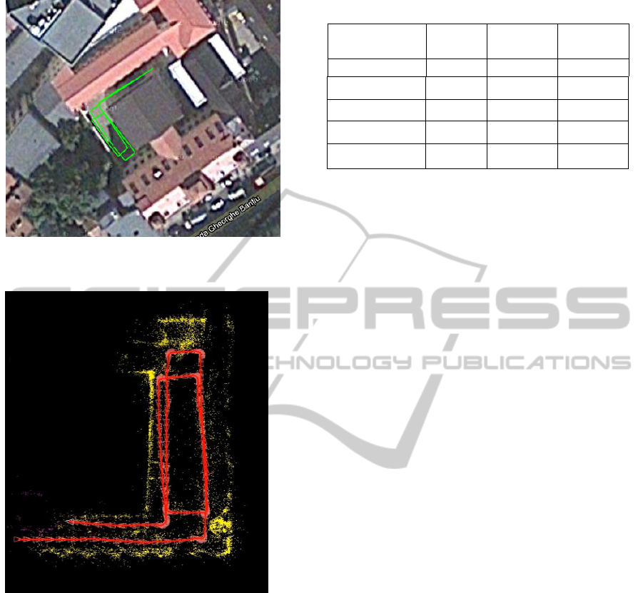
Figure 3: Reconstructed path overlapped on satellite image
data.
Figure 4: Top view of the map (yellow) obtained from
reconstructed 3D points registered based on the computed
successive poses (red).
main algorithm to be divided in three main steps:
feature detection, feature tracking and pose
estimation.
On average the algorithm can process at speeds
higher than 10HZ meaning it can compete with the
rates of other means of localization.
In Fig 3 the trajectory is overlapped on a satellite
image of the test scenario. The image is taken of
Google Maps at smallest scale available.
In Fig 4 we present the result of registering the
reconstructed 3D points based on the information
from VO. This presents the global consistency of the
path while more loops are performed within the
same perimeter.
Table 1: Computing Time.
Computing time
Mean
Minimum
Maximum
[ms]
[ms]
[ms]
Corner Detection
10.3
8
25
Corners Tracking
33.5
10
159
SURF
45
41
51
Pose Estimation
24.8
7
302
Total time
88.6
33
328
5 CONCLUSIONS
The article presents a method of localization that
relies only on stereo vision. We present data
showing that performance depends on the type of the
feature descriptor involved in interest point
detection. We compare results obtained from using
two different descriptors separately as well as
together. Superior results are obtained when using
both feature descriptors in the homography recovery
process. We compare the performance of vision
based localization against wheel encoder odometry.
The far superior precision of the proposed vision
algorithm can be shown in outdoor with challenging
environment. We present data showing that the
algorithm is capable of running at speeds that allow
real time usage. Finally we demonstrate global
consistency of the poses by registering the
reconstructed points with respect to the VO current
pose.
REFERENCES
Nister, D., Naroditsky, O., Bergen, J.,” Visual odometry
for ground vehicle applications”, J. Field Robotics 23,
2006
Howard, A., “Real-time Stereo Visual Odometry for
Autonomous Ground Vehicles”, proc. Internation
Conference on Robots and Systems (IROS), Sep. 2008
Agrawal, M., and Konolige, K., “Rough Terrain Visual
Odometry” In Proc. International Conference on
Adranved Robotics (ICAR), Aug. 2007
Hartley, R., Zisserman, A., “Multiple View Geometry in
Computer Vision” Second Edition, C. U. Press, Ed.
Cambridge, 2003.
Shi, J., Tomasi, C., “Good Features to Track”, IEEE
conference on Computer Vision and Pattern
Recognition (CVPR94), 1994.
Bradski, G., Kaehler, A., “Learning OpenCV: Computer
Vision with OpenCV”, O’Reilly, 2008.
Improving Stereo Vision Odometry for Mobile Robots in Outdoor Dynamic Environments
479

Pojar, D., P. Jeong, Nedevschi S., "Improving localization
accuracy based on Lightweight Visual Odometry",
Intelligent Transportation Systems (ITSC), 2010, p.
641 – 646
Scaramuzza, D., Fraundorfer, F., and Siegwart, R., “Real-
Time Monocular Visual Odometry for On-Road
Vehicles with 1-Point RANSAC”, IEEE International
Conference on Robotics and Automation (ICRA 2009),
2009
Bay, H., Ess, A., Tuytelaars, T., Van Gool, L., "SURF:
Speeded Up Robust Features", Computer Vision and
Image Understanding (CVIU), Vol. 110, No. 3, pp.
346--359, 2008
ICINCO 2012 - 9th International Conference on Informatics in Control, Automation and Robotics
480
