
Development of Mobile Research Robot
A. Baums, A. Gordjusins and G. Kanonirs
Institute of Electronic and Computer Science, Dzerbenes street 14, Riga, Latvia
Keywords: Research Robot, Real Time System, Timelines, TUF, Physical Model.
Abstract: For new autonomous mobile robot design, the real time problem analysis at different periods of robot
activity phases is made. The robot sensor and actuator cluster structure is used. At first the robot is
determined as a hard real time system when all phases defined and executed sequentially are in hard
deadlines. At second for the robot activity with hard and soft deadline execution phases is proposed using of
the time/utility function (TUF). For time and energy consumption estimation, the flexible robot physical
model is developed and used. Wireless technology is proposed for new autonomous mobile robot design.
1 INTRODUCTION
New mobile research robot development for
education and training purpose is urgent, despite
now there are different ready-made research robots
(Adept mobilerobots, 2011a; b), (Segway Robotics,
2012) which were purchased primarily by
researchers. Before new commercial research of
autonomous robot for hard and unstructured
environment design began, there were different
significant problems necessary to solve: position
estimation, obstacle avoidance, motion trajectory
planning and map building, timely and energy
consumption estimation (Choset et al., 2005).
Historically the term “autonomous mobile
unmanned robot” implies a real time system (RTS).
Often systems are estimated and classified as hard,
firm or soft RTS. The required deadline is the
decisive subdivide factor. But it is the determined
parameter of application and environment. When the
deadline failure threatens human life, the hard
design system is obligatory. In other kinds of
applications the permissible complete task execution
time (ET) can be firm but at the same activity
(phase) the RTS can be soft. The hard system can be
considered as a special case of soft RTS.
Generalized timeliness calculation meter
time/utility function (TUF) was proposed by Jensen
in 1976. TUF is a generalization of the deadline
constraint, specifying the utility to the system
resulting from the completion of an activity as a
function of its completion time (Ravindran et al.,
2005). When activity time constraints are expressed
with TUFs, the scheduling optimality criteria are
based on accrued activity utility - e.g., maximizing
the sum of the activities’ attained utilities, assuring
satisfaction of lower bounds on activities’ maximal
utilities. Such criteria are called Utility Accrual
(UA) criteria. It can be especially useful for outdoor
robot control in environment with dynamically
uncertain properties (Balli et al., 2007). An energy-
efficient, utility accrual, realtime scheduling
algorithm called the Resource-constrained Accrual
Algorithm proposed by Wu, Ravindran and Jensen
(2007). Other optimization algorithm called Profit
and penalty aware scheduling algorithm proposed by
Li et al. (2012).
2 TIMELINESS ESTIMATION OF
AUTONOMOUS MOBILE
UNMANNED ROBOT
Autonomous mobile unmanned robots’ general
structure includes: one central unit CU (main
processor), clusters of sensors Sn and actuators Ac
with interface nodes. All nodes and information
lines can be characterized with some real time
properties (time delay, throughput, security).
Activity execution phases for an unmanned
outdoor Robot is represented by N+1 main finite
automata states and different kinds of execution time
intervals T
0
, T
1
,… T
k
, …T
N
. Phases k can include
particular phases or a number of N
k
states and
execution cycles or activities t
kw
. Execution cycles
329
Baums A., Gordjusins A. and Kanonirs G..
Development of Mobile Research Robot.
DOI: 10.5220/0004044303290332
In Proceedings of the 9th International Conference on Informatics in Control, Automation and Robotics (ICINCO-2012), pages 329-332
ISBN: 978-989-8565-21-1
Copyright
c
2012 SCITEPRESS (Science and Technology Publications, Lda.)
can be performed concurrently or sequentially.
Information from different sensors can be obtained
simultaneously. Concurrency of mechanical actuator
and electronic operation execution is especially
important for optimal real time robot design.
At phase zero (time interval T
0
) the registers of
nods are charged with data from the main program.
This program can be hold in ROM of central unit or
loaded using wireless connection from user data
base. This zero phase is not necessary to enclose in
the autonomous mobile outdoor robot real time
characteristic estimation.
Phase one (time interval T
1
) – the environment
estimation and building the route map:
- T
11
the robot start point estimation using GPS
(t
1gp
), data acquisition by video camera module at
start position (t
1vi
, data acquisition from digital
compass (t
1cm
) and data acquisition from infrared
optical short range distance meter (t
1sd
) and infrared
optical long range distance meter (t
1ld
), start point
coordinate estimation (t
1cu
) using CU.
Data acquisition from GPS, digital compass and
distance sensors can be executed simultaneously in
time t
1vi
required to complete data acquisition by
video camera module. Then start point coordinate
estimation in time T
11
is t
1vi
and t
1cu
determined
- T
12
is a sum of times required to turn camera in
horizontal (t
1th
) and vertical (t
1tv
) directions to search
for the first nearest object, using servomotors and
image acquisition time getting information about
recognized objects t
1vi.
This process repeats as much
times N
1tm
as needed to investigate view sector for
the object. T
12
is N
1tm
,t
1th
, t
1tv
and t
1vi
determined.
At the optimal conditions N
1tm
=1
- T
1
route map calculation (t
1cum
) by central unit
using main algorithm and data from GPS, digital
compass, video camera module and distance sensors.
T
1
= T
11
+T
12
+ t
1cum
(1)
Phase two (time interval T
2
) - robot turning to
the required direction actuating both left (t
2trl
) and
right (t
2trr
) motors. Motors are actuated
simultaneously, it can be accepted that their
operation time is equal T
2
= t
2trl
= t
2trr
Phase three (time interval T
3
) – robot movement
by calculated route map to the first, second, or N
st
objects, actuating motor drivers, distance encoders,
video camera module and compass:
- image acquisition by video camera module (t
3vi
)
- driving and steering (t
3ds
) to the object reading
data from distance l encoders
and required direction
α from compass. T
3
is N
st
,t
3ds
, t
3vi
determined.
Phase four (time interval T
4
) –investigation of
object parameters using video camera module (t
4vi
)
and central unit program (t
4cuo
). T
4
is t
4vi
and t
4cuo
determined.
Phase five (time interval T
5
) – obstacle
avoidance: obstacle determination using video
camera (t
5vi
), avoidance decision taking by CU
(t
5cuob
) (jump over or go around), obstacle avoidance
realization (t
5rob
). T
5
is t
5vi
, t
5cuob,
t
5rob
determined.
For the robot real time characteristics’
investigation, it is suitable to select some application
specific limited route map and time interval T
1
for
the calculation and select it as the deadline.
A deadline can be determined for each execution
phase. When sequence of all of the phases can be
determined in WCET
i
(worst-case execution time) -
the robot can be determined as hard RTS.
T
1
= T
1
+ T
2
+ T
4
+ T
5
=∑
i
5
WCET
i
= D
h
(2)
To compare and estimate different robot
realization structures using (1) it is necessary to
select the same numbers of N
1tm
and N
st
.
For sophisticated autonomous mobile robot
timelines with task completion slack time, start time
and soft deadlines utility accrual UA approach can
be used. The Utility (U) depends on the activity’s
completion time for phases T
i
and particular cycles
t
k
. These soft time constraints are subject to
optimality criteria such as completing all time-
constrained activities as close as possible to their
optimal completion time — so as to yield maximal
collective utility. Time/utility functions is a
generalization of the deadline constraint, specifies
the utility to the system resulting from the
completion of activity as a function of its completion
time.
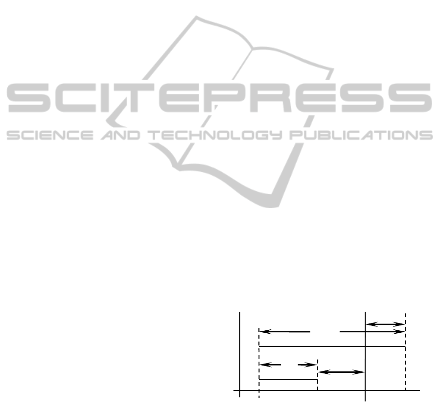
Activity ji utility (U) calculation is useful to
compare the realization time t
ji
and some soft
deadline d
s
(Figure 1.).
Figure 1: Activity j realization with deadline d
s.
This soft deadline depends on environment
where is acting the autonomous mobile robot. While
developing our research robot physical model the d
s
usually was equal to image processing delay (Baums
et al., 2011).
d
s
i
∆
ji(-)
∆
ji(+)
t
ji(-)
t
ji(+)
t
ICINCO 2012 - 9th International Conference on Informatics in Control, Automation and Robotics
330

Performing any tasks there is some probability
p
11(+)
of missing the deadline d
s
. For the activity ji
utility calculation, this time (t
ji(+)
=d
s
+∆
ji(+)
is
ij
τ
ij(+)
d
sij)
designated,
ij
- task starting time point.
For the first activity t
112
(phase one) camera turns
simultaneously in horizontal and vertical directions
(t
1th
t
1tv
):
U
112
=
112
=
12
τ
1ht(-)
d
s12
- p
12(+)
12
τ
1ht(+)
d
s12
(3)
The utility accrual UA of T
11
):
UA
11
=
112
+
1 vi
+
1cu
==
112
+
1vi
τ
vi(-)
d
s1vi
-
-p
1vi(+)
1lvi
τ
1vi(+)
d
s1vi
+
cu
τ
cu
d
scu
(4)
The utility accrual of T
12
:
UA
12
=
12
= N
1tm
(
112
+
1vi
)
(5)
TUF UA
1
= U
112
+ UA
12
+
cu
τ
cu
d
scu
=
=
112
+
12
+
cu
τ
cu
d
scu
=
1
1
d
s1
(6)
To compare this Time/utility function model
with the hard RTS model, it is necessary to estimate
the utility accrual for the same 5 phases (2).
TUF UA =
1
=
1
1
d
s1
+
2
2
d
s2
+
+
4
4
d
s4
+
5
5
d
s5
= D
s
D
h
;
(7)
The realization time τ
ji
, starting point
ji
and soft
end point d
sji
estimation can be made by using some
mathematical or physical models (Baums et al.,
2011).
For system energy and cost minimization,
decreasing of the node number is efficient. For
example, one node can be used to transfer data for
more than one different sensors or actuators.
3 DESIGN AND INVESTIGATION
OF AUTONOMOUS MOBILE
ROBOT
3.1 Robot’s Physical Model
Flexible physical model for autonomous robot time
and energy consumption investigation is developed
and published by the authors (Baums et al., 2011).
Aerial view of physical model it is proposed on
Figure. 2. There is only one node (system node) for
actuator (ac - motors) and video camera (se - vision)
connection. Other sensors (se - Compass CMPS03,
optical range meter Sharp GP2D15 and
GP2Y0A710YK) are directly connected to the
central unit.
The autonomous robot trip in real environment
with different objects was investigated and ant-
colony algorithm was used to build shortest round
trip route (Baums et al., 2011). Robot’s physical
model mainly is used for research and student
education.
Figure 2: Mobile robot’s physical model aerial view.
Physical model’s peak energy consumption was
experimentally estimated. The following results
were obtained: Control board (5V ∙50ma=0.250W);
2 SHARP range meters (2∙5V∙50ma=0.500W);
compass CMPS09 (5V∙25ma=0.250W); camera
CmuCam3 (10V∙450ma=4.5W); 2 servo motors
(2∙5V∙750ma=7.5W); motor driver (5V∙50ma=
0.250W), 2 motors (2∙10V∙3.50a=70W); maximal
energy consumption: ∑
ei
~ 83W.
3.2 Autonomous Mobile Robot’s
Design using Wireless Technology
As a central unit for the new generation autonomous
mobile robot design was used PDA HTC Flyer. The
structure of the robot is proposed on Figure 3.
Main differences between first and second
mobile robot physical models are:
- Video camera module. First robot used
CmuCam 3 built by Carnegie Mellon Univercity. It
had some disadvantages – such as low image
resolution, low data transfer rate, camera matrix low
sensitivity to the red color. New robot uses built in
High-Quality 8Mpix camera module. Because
Camera module and system processor are placed on
one module – HTC Flyer, image data transfer and
processing speed increased greatly.
- Navigation system. For the navigation purposes
first robot used electronic compass CMPS09,
encoder system, and range finders. New system uses
Sparkfun 9DOF AHRS module instead of CMPS09.
It includes 3 axis magnetic compass, 3 axis gyro, 3
axis accelerometer and ATmega328 for data
processing and transfer purposes. Using adaptive
filter (Kalman filter) AHRS module helps to make
much more precise robot position and direction
Development of Mobile Research Robot
331

Figure 3: Autonomous mobile robot built using wireless technology.
determination then just an electronic compass.
- CU. Main control unit of the first robot was
ATmega32. As a control unit for a new robot HTC
Flyer was chosen because of its powerful processor.
It is capable to perform calculations quickly.
- Communication abilities. The robot is capable
of communication using 3G or Wi-Fi networks. It
helps an operator to control robot and get telemetry
data from any place in the world where there are
available connection to the Internet.
Such a solution for the mobile robot is very flexible
giving ability to scale it for a task.
One of the first test tasks planned to realize on
built physical model is to detect colored markers in
the preset environment, estimate their position, build
shortest round trip route and move through it.
4 CONCLUSIONS
For the new autonomous mobile research robot
design, the real time problems are significant and it
is necessary to solve it in estimated time. For timely
analysis, an autonomous robot’s structure is based
on a single main processor, clusters of sensors and
actuators with its interface nodes. In different
robot’s activity phases the time/utility function TUF
and utility accrual UA criteria are selected.
For time and energy consumption experimental
estimation robot’s physical model is used. This
model is advisable for student education.
The new autonomous mobile robot is designed
using proposed wireless technology.
ACKNOWLEDGEMENTS
This work has been supported by European Social
Fund, grant Nr. 2009/0219/1DP/1.1.1.2.0/APIA/
VIAA /020 and Latvian Council of Science.
REFERENCES
Baums A., Gordjusins A., Kanonirs G., 2011.
Investigation of Time and Energy Consumption using
the Physical Model, Electronics and Electrical
Engineering, 5, pp.85-88.
Adept Technology, 2011a. Mobile robot Seekur. [online],
Avilable at: <http://www.mobilerobots.com/ research
robots/Seekur.aspx> [Accessed 1 May 2012]
Adept Technology, 2011b. Pioneer 3 DX. [online] <http://
www.mobilerobots.com/researchrobots/pioneerp3dx.a
spx> [Accessed 1 May 2012]
Ravindran B., Jensen E. D., Li P., 2005. On Recent
Advances in TUF Real-Time Scheduling and Resource
Management, In Proceedings of the 8 IEEE
International Symposium on Object-Oriented Real-
Time Distributed Computing, pp55-60.
Choset H., et al., 2005. Principles of Robot Motion:
Theory, Algorithms, and Implementations, MIT Press.
Wu H., Ravindran B., Jensen E.D., 2007, Utility Accrual
Real-Time Scheduling Under the Unimodal Arbitrary
Arrival Model with Energy Bounds. IEEE
Transactions on Computers, 56(10), pp.1358-1371.
Segway Robotics, 2012. RMP400. [online] Avilable at:
<http://rmp.segway.com/rmp-400-omni/> [Accessed 1
May 2012]
Li S., et al., 2012, Profit and Penalty Aware Scheduling
for Real-Time Online Services. IEEE Trans. Industrial
Informatics, 8(1), pp.78-89.
Balli U., Wu H., Ravindran B., Anderson J. S., Jensen E.
D., 2007. Utility Accrual Real-Time Scheduling under
Variable Cost Functions, IEEE Transactions on
Computers arch. 56(3), pp.358-401.
CU (HTC Flyer)
Bluetooth
System node (MSP430F1611)
AHRS
system
Sparkfun
9DOF
Sharp
range
meter
(1.5m)
Motor left
Motor right
Encoder left
Encoder right
System node (demultiplexer M74HC4053)
Motor driver
Sharp
range
meter
(5m)
Environment
Built in camera system
GPS
Servomotor
- H
Servomotor
- V
Wi-Fi, 3G
ICINCO 2012 - 9th International Conference on Informatics in Control, Automation and Robotics
332
