
Robust Control of Excavation Mobile Robot with Dynamic
Triangulation Vision
Alexander Gurko
1
, Wilmar Hernandez
2
, Oleg Sergiyenko
3,1
, Vera Tyrsa
1
,
Juan Ivan Nieto Hipólito
4
, Daniel Hernandez Balbuena
4
and Paolo Mercorelli
5
1
Kharkov National Automobile and Highway University, Kharkov, Ukraine
2
Polytechnic University of Madrid, Madrid, Spain
3
Engineering Institute of Autonomous University of Baja California, Mexicali, Mexico
4
Engineering Faculty of Autonomous University of Baja California, Mexicali-Ensenada, Mexico
5
Leuphana University, Lüneburg, Germany
Keywords: Excavation Robot, Robust Control, Game Approach, Multiple Identification.
Abstract: The problem of control system synthesis for excavation works autonomous mobile robot on the basis of the
game approach is considered. Vision function and spatial orientation of the robot is realized by the dynamic
triangulation laser vision system. It is assumed that the real state of the object belongs to the certain set of
potential states in the form of polyhedron. Simulation results and functional ability analysis for the proposed
control system are concluded.
1 INTRODUCTION
Progress of autonomous mobile robots for
excavation works (EMR) is stimulated with
numerous applications in various areas of human
activities. Such robots are equipped by bulldozer
blade and should in autonomous mode rid the area of
obstacles, profile surface along the dead-reckoning
track, etc.
One of the key challenges in application of EMR
is navigation in environments that are densely
cluttered with obstacles and has a rough terrain. The
challenge of an intelligent control system in mobile
robot navigation it is caused by uncertainties
associated with sensory systems and the dynamic
environment. It causes various approaches (Lamon,
2007; Selekwa, 2008) to this task solution. However,
none of them still not reach a complete solution
enough for full scale industrial manufacturing of
such robot. The key problem is a proper mutual
complementation of a sensory systems and
corresponding robust control algorithm.
2 PROBLEM FORMULATION
For EMR performance have to get an environment
model, define self location inside, plan its trajectory
and operate blade and, at the same time, functioning
in a changeable environment. The critical particular
features of EMR are: work time and the guaranteed
accuracy.
The main methods which are used in EMR
control synthesis at uncertainty conditions is fuzzy
logic (Selekwa, 2008) and self-organizing neural
networks (Miller, 1996). But peculiarity of EMR
functioning reduce efficiency of such control
systems use. The initial set of the postulated fuzzy
rules may be incomplete or contradictory, and the
kind and parameters of membership functions that
describe system’s variables may reflect reality not
quite sufficiently. The use of adaptive neuronetwork
control systems is criticality limiting the requirement
of operating time, and it becomes crucial.
The game approach guarantees that processes
will remain satisfactory at any sets of uncertain
factors. In our opinion, it is expedient for robust
control to use the next pair: 1) sensory system
providing real time continuous feedback in Cartesian
coordinates, and 2) control system based on the
game approach (Eryemenko, 2009).
481
Gurko A., Hernandez W., Sergiyenko O., Tyrsa V., Ivan Nieto Hipólito J., Hernandez Balbuena D. and Mercorelli P..
Robust Control of Excavation Mobile Robot with Dynamic Triangulation Vision.
DOI: 10.5220/0004044604810484
In Proceedings of the 9th International Conference on Informatics in Control, Automation and Robotics (ICINCO-2012), pages 481-484
ISBN: 978-989-8565-22-8
Copyright
c
2012 SCITEPRESS (Science and Technology Publications, Lda.)
3 SENSORY SYSTEM FOR
ENVIRONMENT MODEL
In literature is known only unique technical vision
system (TVS) which can provide the environment
model in Cartesian coordinates in real time, or a
system with digital mapping of the obstacles surface
in fixed field-of-view. Its detailed description is
given in (Sergiyenko, 2009; Rivas, 2008;
Sergiyenko and Hernandez, 2009). Its general view
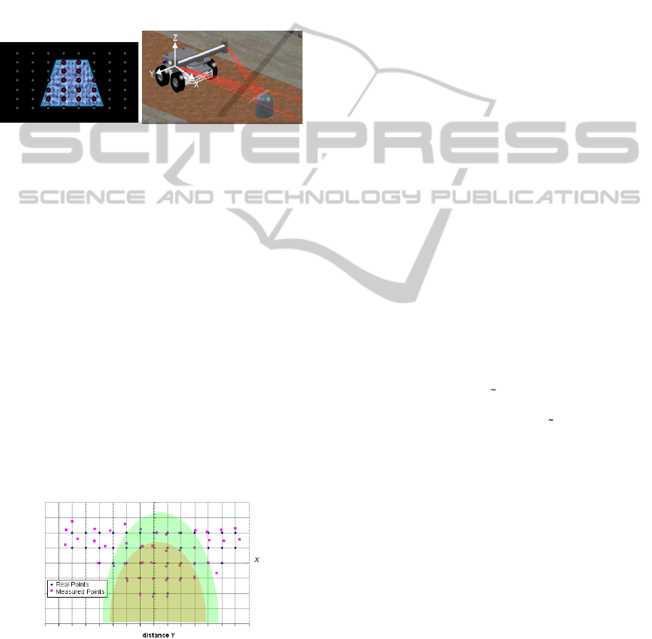
is given on Fig.1.
a) b)
Figure 1: TVS Operation principle: a) isometric view; b)
digital mapping of visible obstacle surface.
Each point highlighted on the obstacle surface
(Fig.1,b) by laser beam of is called S
ij
. For each S
ij
are obtained X,Y, and Z Cartesian coordinates set by
formulas presented in (Sergiyenko, 2009; Rivas,
2008; Sergiyenko and Hernandez, 2009). The
accuracy of coordinates measurement is not uniform
(Fig. 2) in field-of-view, but in the olive- and green-
zone correspondingly it is not more than 1% and 4%
out of level of confidence (Rivas, 2008; Sergiyenko
and Hernandez, 2009). Usually, modern regular step
drives are operated with average velocity of 1 KHz,
so we can obtain coordinates at least of 1000 points
per second, each X, Y, and Z with metrological
accuracy and known uncertainties. This is a point to
apply this TVS as input data sensory system
(Sergiyenko, 2009; Rivas, 2008; Sergiyenko and
Hernandez, 2009) for game approach control
(Eryemenko, 2009; Gurko, 2011) realization.
Figure 2: TVS field-of-view and “accuracy zones”.
4 CONTROL OBJECTIVE
Given is the uncertain discrete-time system
1n n n n
X AX BU CF
,
(1)
where X
n
R
m
, n = 0,1,…, N, is the state vector;
U
n
R
q
, n = 0,1,…, N - 1, is the control vector;
F
n
R
r
, n = 0,1,…, N - 1, is the input disturbance
vector; A, В, С are matrixes of corresponding
dimensions, n – sampling time, n = 0,1,2,…
(instances of: TVS interrogation/ control action
implementation).
Available to the controller are measurements of
the form
Y
n
=X
n
+Z
n
,
0,1,..., 1nN
(2)
where
s
n
YR
is the measurement vector;
v
n
ZR
is the measurement noise vector.
About vectors F
n
and Z
n
it is known only that are
belongs to prescribed guaranteed bounded sets
F
nn
F
,
Z
nn
Z
, n 0.
(3)
According to the game approach to the optimal
control of uncertain dynamic system the controller
on each sampling step n has to solve the following
task
min max max , , ,
U
FZ
nn
n n n n
n n n
U
FZ
X U F n
,
(4)
where
U
n
is a given set of control actions;
()
is a
specific losses function:
1
, , ,
n n n
V X n X U n
,
(5)
where V() is Lyapunov function,
()
is a given
function, defines control costs and assigns
limitations on their value.
Relate to EMR control task of the advantage of
the considered approach is in the following. Using
the model (1) and equations (2) and (3) at each
sampling step n > 0 the set
X
n
of possible EMR’s
states is carried out and the control U
n
solving
problem (4) is defined. The main problem is
identification of set
X
n
of the object possible states
taking to account external disturbances and noise in
sensing system.
5 CONTROL DETERMINATION
For simplicity we will consider 2D case, when U
n
ICINCO 2012 - 9th International Conference on Informatics in Control, Automation and Robotics
482

and F
n
in (1) and Z
n
in (2) are scalar quantities. Note,
that with increasing of object order, the procedure
described below does not change. About F
n
it is
known that it satisfies the constrain - f
n
, where
is any rational number. Measurement of space
orientation of the robot is carried out with a noise Z
n
,
- Z
n
, where is any rational number.
For 2D case the state vector
12
[ , ]
n n n
X X X
; the
observable output (a robot’s angle of yaw)
1
[ ,0]
nn
YX
. The control U
n
is determined by the
following algorithm.
1. At n = 0 the output value Y
0
is measured. The
state estimation is not a point value but a set of
admissible states due to measurement noise, and to
unknown rate of coordinate Х
1
changes. This set is
located in a vertical dashed bar
00
XS X
which is
symmetric concerning the measured value
0
O
Y
of the
object output Y
0
and bounded with parallel
2
0
X
axis
lines (see Fig. 3 a).
2. The control
0
O
U
action should move the object
from the state X
0
into a state X
1
. But since the
object’s actual state is unknown, the set of its
possible states at the moment n=1 is defined as
follows. The set
0
X
is being reflected at coordinate
system
12
11
,XX
with the matrix A of eq.(1). The new
set
0,1
X
contains those states, in which the control
object can get starting from
0
X
in a self movement.
The set
0,1
X
is moved along the vector
В = (b
1
, b
2
) on
0
O
U
value, thus the set
0,1
XB
will be
generated (see Fig. 3b). It’s a forecast of the EMS
possible states after control
0
O
U
action, but in
absence of disturbance F
0
.
3. Disturbance F
0
leads to the transformation of
the set
0,1
XB
to the set
0,1 0,1
XF XB
with the vector
C. The set
0,1
XF
is a set of the object’s predictable
states at n = 1, taking into account existing control
0
O
U
together with disturbance F
0
.
4. The next set
1
X
of system potential states at
n = 1 have been computed as a result of intersecting:
1 1 1
X XF XS
, where the set
1
XS
is an infinite
bar, that 2 wide and symmetrical relative
1
11
O
XY
.
a) b)
Figure 3: a) Set
0
X
; b) Set
1
X
.
5. The U
1
is evaluated to solve the task (4).
6. The set
2
X
is been built in a similar manner.
The previous set
1
X
is moved with the control U
1
,
transformed with the vector C and is intersected with
a bar of new observation
2
XS
, and further the
procedure iteratively repeats.
6 NUMERICAL EXAMPLE
Consider the example of control definition that
based on mentioned algorithm. Let EMR’s dynamic
describes by difference equations (1) and (2) with
next parameters
0.9822 0.2125
0.0893 0.7120
A
;
0.0281
0.2125
B
.
Let's consider also disturbance F
n
is pulsed and
satisfy the constrain
0.025
n
F
. Consider the
optimal value of the cost function (6):
2 2 2
12
0
min ( ) ( ) 0.5 ( )
n
J X n X n U n
,
(6)
The MATLAB solution of the given task is
presented above on Figs. 4-6. The Fig. 4 shows a
graphics of system’s output Y
n
, disturbance F
n
, and
control U
n
that minimized the function (6) value.
Fig. 5 shows the values of measurement noise. It
was assumed that the measurement noise is in the
foregoing range
0.025
n
F
and is subject to a
uniform distribution law. On Fig. 6 the area of
possible states
X
n
at steady state (n=30) is
presented.
Robust Control of Excavation Mobile Robot with Dynamic Triangulation Vision
483
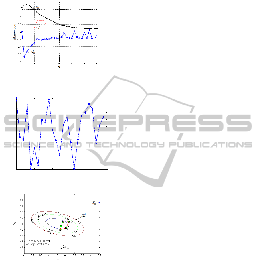
Figure 4: Graphics of: a) modification of system output Y
n
,
disturbance F
n
and control U
n
.
0 5 10 15 20 25
-0.025
-0.02
-0.015
-0.01
-0.005
0
0.005
0.01
0.015
0.02
0.025
measurement noise
n
Magnitude
Figure 5: The measurement noise.
Figure 6: Set
X
n
of potential EMR’s states at n=30.
As evident from Fig. 4-6 the proposed controller
ensures enough control quality. For system quality
improvement it is necessary to use the observer
giving a specified multiple rating of possible
perturbations at each control step.
7 CONCLUSIONS
In this paper we considered the problem of robust
control of EMR. The unique technical vision system
for EMR’s sensory system, providing real-time
continuous feedback in Cartesian coordinates, was
proposed. A new algorithm was given for the state
filtering for robust control determination.
The presented algorithm allows intersect convex
polyhedrons. As the actual systems are nonlinear, it
is necessary to be able to intersect non-convex sets.
It is an objective for future work. Also expedient to
note that additional increase of technical vision
resolution in future can be reached by
implementation of our original method of scales
binding described in (Sergiyenko, 2011).
ACKNOWLEDGEMENTS
This work has been supported by the Ministry of
Science and Innovation (MICINN) of Spain under
the research project TEC2010-17429, and the
Universidad Politecnica de Madrid under the
research project AL12-PID-31.
REFERENCES
Eryemenko, I., Gurko, A., 2009. Realization of the Game
Approach to Control of Second Order Linear Objects.
Journal of Automation and Information Sciences,
Begell House Inc., NY, USA, Vol.: 41, pp.10-22.
Gurko, A., Eryemenko, I., 2011. Control of discrete
system under bounded disturbances. Journal of
Automation and Information Sciences, Begell House
Inc., NY, USA, Vol.: 43, Issue 11, pp. 18-29.
Lamon, P., Siegwart, R., 2007. 3D Position Tracking in
Challenging Terrain. The International Journal of
Robotics Research, Vol.: 26, pp.167-188.
Miller, W. T., Sutton, R. S., Werbos, P. J., 1996. Neural
Networks for Control, MIT Press, 5
th
edition, 542 p.
Rivas, M., et al., 2008. Spatial data acquisition by laser
scanning for robot or SHM task. In ISIE’08, IEEE-IES
International Symposium on Industrial Electronics,
Cambridge, United Kingdom, pp.1458-1463.
Selekwa, M. F., Dunlap, D. D., Shi, D., Collins, E. G.,
2008. Robot navigation in very cluttered environments
by preference-based fuzzy behaviors. Robotics and
Autonomous Systems, Elsevier, Vol: 56, pp. 231-246.
Sergiyenko, O., Hernandez, W., et al., 2009. Remote
Sensor for Spatial Measurements by Using Optical
Scanning. Sensors, Basel, Switzerland, 9(7), pp. 5477-
5492.
Sergiyenko, О., Tyrsa, V., Devia, L., Hernandez, W., et al,
2009. Dynamic Laser Scanning method for Mobile
Robot Navigation. In ICCAS-SICE’09, ICROS-SICE
International Joint Conference, Fukuoka, Japan,
August 18-21, pp. 4884-4889.
Sergiyenko, O., et al., 2011. Analysis of jitter influence in
fast frequency measurements. Measurement, Elsevier,
Vol. 44, Issue 7, pp. 1229-1242.
ICINCO 2012 - 9th International Conference on Informatics in Control, Automation and Robotics
484
