Design and Experimentation of a Neural Network Controller
for a Spherical Parallel Robot
Donatello Tina, Luca Carbonari and Massimo Callegari
Department of Industrial Engineering & Mathematical Sciences, Polytechnic University of Marche, Ancona, Italy
Keywords: Neural Networks, Robot Control, Parallel Kinematics Machines.
Abstract: The paper deals with a neural network control for the gravity compensation of a parallel kinematics robot.
The network has been designed in a simulation environment then it has been implemented in robot’s
controller by using an FPGA device that is part of an embedded system. After the training phase, several
experiments have been performed on the prototype manipulator and the related datasets have been collected
and elaborated. In the end, a comparative analysis has shown the improved performance of the neural
network controller with respect to the inverse dynamics one, mainly due to the well-known difficulties in
deriving explicit models of friction and play in the joints.
1 INTRODUCTION
During the last two decades, research in the
Artificial Neural Network (ANN) field has increased
significantly in different branches of science. To the
best of our knowledge, King and Hwang (1989) first
theorized the application of ANN for robotics
applications; Narendra and Parthasarathy (1990)
demonstrated that Neural Networks can be also
usefully exploited for the modelling of dynamic
systems as well as for the control of automated
machinery. Other recent robotics applications for
neural networks are the solution of the kinematics of
a parallel manipulator (Zhang and Lei, 2011) and the
control of a planar robot (Serrano, 2011).
Field Programmable Gate Arrays (FPGA) can
perform a large number of parallel operations at very
high time rates and their architecture is very suitable
for the implementation of real time neural networks.
As a matter of fact remarkable realisations are
available already in scientific literature, e.g.
Orlowska-Kowalska et al. (2011) used an FPGA-
based ANN for the state estimation of a two mass
system with elastic couplings.
The main target of the present work is the
realisation of a gravity compensation module for the
control of a prototype parallel manipulator, named
Sphe.I.Ro. whose kinematics allows only motions of
pure rotation. The computation of the analytic model
of machine’s statics is quite burdensome due to the
presence of the closed kinematics chains. Therefore
an ANN has been created in order to obtain a
reliable and efficient static model of the robot, that is
able to provide the actuation forces needed to
maintain a certain configuration in the orientation
space.
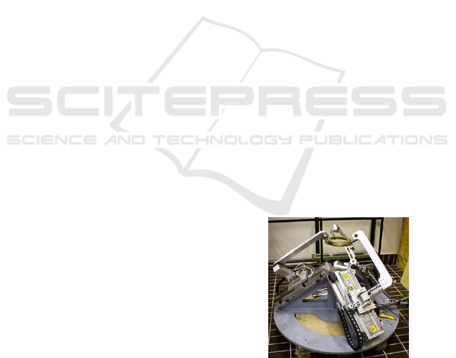
Figure 1: Photograph of the Sphe.I.Ro. robot.
2 THE Sphe.I.Ro. ROBOT
Sphe.I.Ro. (Spherical Innovative Robot) is a parallel
kinematic machine developed at the robotics
laboratory of the Polytechnic University of Marche.
It is made by three identical serial chains connecting
the moving platform to the fixed base, as shown in
Figure 1; each leg is composed of two links: the first
one is connected to the base by a cylindrical joint
(C) while the second link is connected to the first
250
Tina D., Carbonari L. and Callegari M..
Design and Experimentation of a Neural Network Controller for a Spherical Parallel Robot.
DOI: 10.5220/0004047602500255
In Proceedings of the 9th International Conference on Informatics in Control, Automation and Robotics (ICINCO-2012), pages 250-255
ISBN: 978-989-8565-21-1
Copyright
c
2012 SCITEPRESS (Science and Technology Publications, Lda.)
one by a prismatic joint (P) and to the end-effector
by a universal joint (U); for this reason its
mechanical architecture is commonly called 3-CPU.
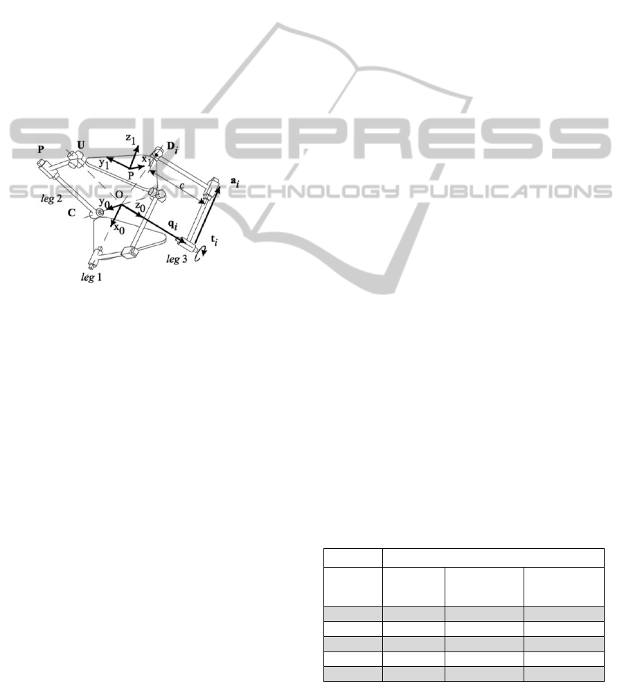
Figure 2 shows a sketch of robot’s kinematics: when
the translations of the three cylindrical joints are
actuated, the end effector is only allowed to perform
pure rotations around a fixed point of the space
(Callegari et al., 2004). The large number of passive
prismatic pairs, typical of parallel kinematics, causes
high friction losses, which represent a relevant
disturbance for motion control and make quite
difficult the realisation of a good dynamic model of
the robot. Therefore the A.’s decided to turn to an
empirical model that could robustly take into
account these phenomena; in particular, the resort to
ANN’s systems proved able to fit the physical
behaviour of machine, obviously after a proper
training phase.
Figure 2: Schematic representation of robot’s kinematics.
3 DESIGN OF THE ANN SYSTEM
3.1 ANN Model
If the model of a single neuron is taken into
consideration, its output can be expressed as:
(1)
where x is the input vector, W is a weighting vector,
b is the bias number and σ is the activation function.
According to Cybenko’s theorem (Cybenko, 1989) a
static feedforward net with one hidden layer of
neurons has been chosen, with the number of
neurons n to be selected after some simulation trials,
as explained in the following section; the input of
the net are the 3 displacements q
i
of the actuators
while the output is represented by the 3 forces f
i
that
keep the robot at rest in the assigned configuration.
The resulting model of the whole net has the form:
(2)
where:
;
;
;
.
3.2 Simulation Network
A simulation model of the network was developed in
order to select the appropriate number of neurons for
the hidden layer and to tune the training procedures.
Both kinematic and dynamic models of the robot
were available already (Callegari et al., 2004, 2012):
it is remarked that the latter has been built according
to the virtual work principle, therefore resulting very
compact and efficient, potentially allowing a real-
time use.
Once set up the simulation environment, several
parameters of the ANN have been changed to look
for best gravity compensation performance. Every
net configuration has been tested after a proper
training, realized by using data sets of about 3 500
different orientations inside robot’s workspace. If
the latter is mapped into the joint space, it is
represented by a tetrahedron whose lateral faces are
singularity surfaces (Carbonari, 2012). For each test
configuration, the gravity force reflected to the
actuators was calculated by using the mathematical
model, therefore obtaining both input (joint
positions) and output (reflected gravity forces) data
set for the training of the net.
The ANN training has been performed by means
of the Levemberg-Marquard back-propagation
algorithm (Hagan and Menhai, 1994). The back-
propagation algorithm needs data to be pre-
processed in order to normalize the input of the net.
Nets with different numbers of neurons have
been investigated (see Table 1 for details); in each
case, the training has been interrupted when the
output error or the gradient became lower than a
given threshold. Simulation results showed that 20
neurons are a good compromise between net
complexity and net performance. It is noted that a
mean square error of about 26 mN has been achieved
throughout the workspace for the 20 neurons net:
this, for a mean actuation effort of about 48 N,
corresponds to a relative error lower than 1%.
Table 1: Training performance of different nets
(simulation).
Training stop criterion
No. of
neurons
Gradient
threshold
Actual
gradient
Performance
(mean square
error)
15
0.009
0.0090
0.0429
20
0.009
0.0080
0.0263
25
0.009
0.0500
0.0268
30
0.009
0.0072
0.0314
40
0.009
0.0088
0.0198
Design and Experimentation of a Neural Network Controller for a Spherical Parallel Robot
251
4 ANN IMPLEMENTATION ON
FPGA
The performance of the artificial neural network has
been experimented on the Sphe.I.Ro. robot, whose
control architecture is briefly described in the
following. The parallel robot is actuated by three
brushless linear motors, whose drivers are connected
to a PXI platform (by National Instruments) which
performs both control and supervision tasks. The
PXI device hosts an FPGA board, which deals with
several processes, such as managing encoders
signals, commanding the brakes of the 3 linear axes,
running the neural network and operating the pre-
and post-processing of network’s input and output.
By grouping the elementary operations of the
ANN for layers, it is possible to implement the net in
LabView by means of two nested “for loops”, as
shown in Figure 3: the inner one for the
multiplication between the input and the
corresponding weight, and the outer one for the
implementation of neuron’s calculations. Figure 3
shows the hidden layer of the ANN, in case 20
neurons are used: x is the input vector of the net and
W is the weights matrix, where w
ij
represents the j
th
weight of i
th
neuron. It is noted that the activation
function σ
H
is the same for all the neurons. The
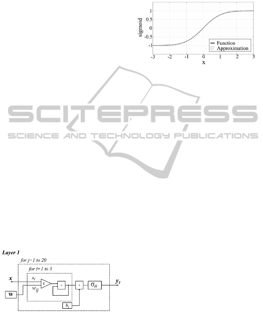
activation function has been realised by means of the
sigmoid tanh(x). According to Kwan (1992) an
approximation of a sigmoid function can be
implemented by using a sigmoid-like second-order
piecewise function
:
(3)
where and determine respectively the slope and
the gain of the nonlinear function (3) while L
represents the amplitude of the non-linear region.
Figure 3: Scheme of the neural network structure
implemented on the FPGA device.
In this work L=2 was used, see Figure 4. This
makes possible to evaluate the activation function by
means of two multiplications and one summation.
Figure 4: Sigmoid activation function σ_H (x) and its
approximation Γ(x).
5 CONTROL ALGORITHM
DESCRIPTION
The implementation of the software in the LabView
environment has been made through its typical
graphic language. Two types of code had to be
written: the ANN has been implemented on the
FPGA board while all other control software had to
run on the PXI controller, which supervises the user
interface and manages the manipulator’s control
system.
Furthermore an interrupt-based procedure
ensures the synchronization between the different
hardware components: in fact, the two devices run at
different clock rates, i.e. a maximum clock rate of
40 MHz for the FPGA board and 10 MHz for the
PXI controller. In order to optimize the FPGA
performance, the code has been partitioned into
different processes, able to perform in-parallel
different real-time tasks, i.e. encoder’s signals
processing, motor driving, ANN system computation
and safety procedures management.
In the PXI controller a Virtual Instrument was
implemented, by exploiting a series of routines that
guarantee the correct execution of the ANN on the
FPGA. In fact the net was designed and tuned in
Matlab and then adapted for real-time execution in
the LabView environment. Thus relevant data of the
net, such as weights matrix, bias vector, pre-process
and post process settings, were first set up in the
Matlab simulation environment and then exported to
the LabView one.
It is useful to assess and compare the
computation efforts needed by both gravitational
compensation models.
As for the ANN model, of course the
computation burden depends upon the number of
neurons that compose the net. For the net that has
ICINCO 2012 - 9th International Conference on Informatics in Control, Automation and Robotics
252
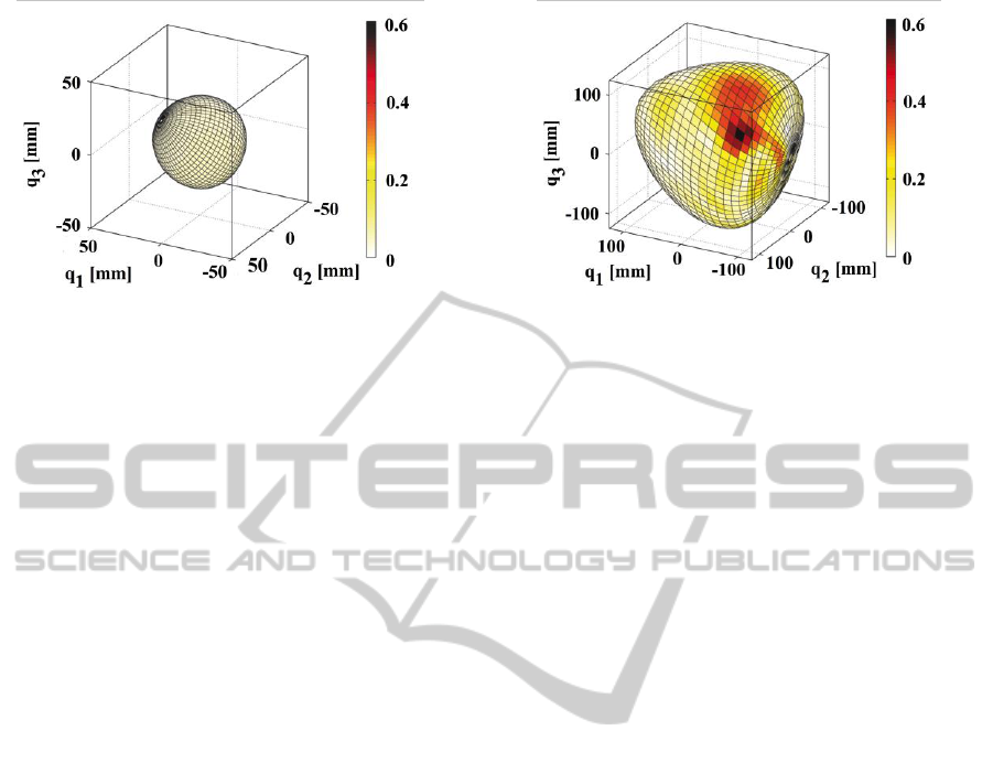
(a) (b)
Figure 5: Norm of the error on different surfaces of joints space (different scales are used): (a) surface close to home
configuration, (b) surface close to workspace boundaries.
been actually implemented on robot’s controller
(one hidden layer with 20 neurons, 3 input and 3
output), the computation of gravity forces requires
166 multiplications and 43 summations.
If the analytical model is used, a huge number of
non linear operations must be used. In particular, an
algorithm based on this model involves 8305
operations, of which 532 are trigonometric
operation.
6 RESULTS
6.1 Simulation Tests
Several tests have been performed in order to
estimate the performances of the ANN gravity
compensation module. First, the entire workspace of
the Sphe.I.Ro. robot has been investigated through
computer simulation, by computing the gravity
compensation forces with the two available models,
i.e. the analytical model and the neural network
model. The deviation between the two models can
be evaluated as:
(4)
where
are the 3 motor thrusts compensating
the gravity force computed by the mathematical
model while
is the corresponding force
vector evaluated by the ANN in the simulation tests.
Each point of the surface visible in Figure 5a
represents a specific robot’s pose in the
neighbourhood of home configuration while the
surface of Figure 5b lays closer to workspace
boundaries. In both cases the norm of error vector
(4) is represented by different colour levels. Since
darker regions mean higher error values, it is
apparent that the error is relevant (
0.4 N) only
within a very limited region of the space. As a
matter of fact, the error becomes lower and lower as
the home configuration is approached: this is due
both to the choice of the training points and to the
increasing isotropy of robot kinematics. In fact,
during training, the points of the dataset have been
made denser in this part of the workspace, where
most operations are carried on.
The behaviour of both the neural network and the
analytical model can be better visualized in the task
space. To this aim, the orientation of the platform is
described by means of the elevation, azimuth and
torsion angles (
). By keeping the torsion angle
(
as a parameter, the error in the orientation space
can be represented as a function of elevation and
azimuth only: for instance, each point of the surface
in Figure 6a represents the norm of the error for a
configuration that is given by elevation
(the angle
around the base circle) and azimuth
(the polar
distance from the centre of the base circle). Figure 6
and Figure 7 represent the error evaluated in
simulation for a null torsion angle (
) and for a
torsion angle
respectively: this task space
representation clearly shows how the error increases
while workspace boundaries are approached, even if
it is pretty limited anyhow. It is noted that the peak
error values emerging in these figures are higher
than the errors that can be read in Figure 5 because
the corresponding points are external to those
surfaces and therefore they are not mapped there.
The prototypal machine is affected by significant
friction forces and bodies deformations, which can
be hardly evaluated in symbolic models, therefore it
was expected that the ANN based model would
perform better than the analytic model: the following
experimental tests aimed at assessing this point.
Design and Experimentation of a Neural Network Controller for a Spherical Parallel Robot
253
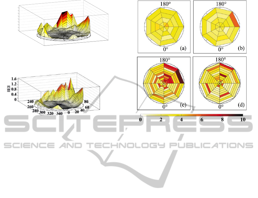
Figure 6: Error plot in the orientation space for
(simulation tests).
Figure 7: Error plot in the orientation space for
(simulation tests).
6.2 Experimental Tests
In order to collect the experimental dataset for the
training of the net, a PID controller has been used to
bring (and keep) the manipulator in all the selected
points of the workspace. Once Sphe.I.Ro. had been
driven to a new pose, the forces necessary to
maintain the robot in such configuration have been
recorded by measuring the current absorbed by
motors. The brushless linear motors used to drive the
rig have a proportional dependence between current
and force: the related constant is called “thrust
constant” (K
t
) and is provided by the manufacturer.
During the experimental tests, the robot has been
commanded to attain several orientations in the
workspace (different from the ones in the training
set) and the actual forces required by the actuators,
, have been compared with both the forces
estimated by the ANN,
, and the ones
provided by the analytical model,
. The arising
errors are:
(5)
(6)
Figure 8 allows a comparison between the
behaviours of the two models of gravity
compensation (analytical and ANN based): since the
two graphs have quite similar values, some critical
indicators are collected in Table 2.
In order to get more insight into this key issue,
Table 2 also presents the experimental performance
Figure 8: Actuation forces errors in different points of the
space:
(a) and
(b) for
=0;
(c)
and
(d) for
=15°.
of the ANN based controller, in case the training is
performed on the simulation data set (in place of the
on-field training); all the data are provided for both
torsion angles (
=0° and
=15°). It can be seen that
the performance of the ANN controller is better than
the analytical based one in all conditions tests, but
the difference is scarcely substantial. As could be
expected, such difference in performance becomes
smaller as the boundaries of the workspace are
approached and/or the values of the torsion angle
increases since less points have been taken in these
conditions for ANN training and, on the other hand,
the analytical model is able to capture, at least
partially, the rapidly changing manipulator’s
dynamics close to singular configurations.
In the end, it can be useful to investigate the
causes of the not completely satisfying behaviour of
the ANN based compensation: first of all, due to the
relevant time needed by on-line experiments, only
100 points have been considered to build the
experimental data set for net training (while 3000
points have been used in the simulations). Secondly,
due to the lag induced by static friction, for any
configuration of the manipulator there exist a whole
range of actuation forces that keep the machine in
equilibrium under the effect of gravitational force:
such effect surely affected the training phase and
thus the performance of the ANN compensation.
0
0.4
0.8
1.2
1.6
60
80
40
20
0
340320
300
280
260
||E||
240
ICINCO 2012 - 9th International Conference on Informatics in Control, Automation and Robotics
254
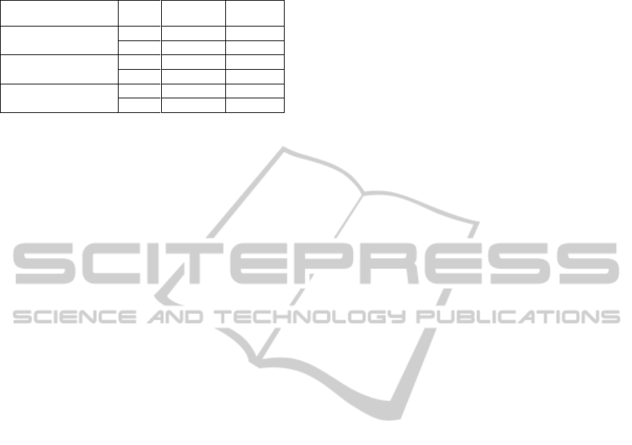
Table 2: Performance indexes of gravity compensation
models.
Max
error[%]
Ave
error[%]
ANN compensation
(on-field training)
=0°
7,0
2,8
=15°
11,5
4,6
ANN compensation
(simulation training)
=0°
9,0
3,8
=15°
13,6
4,9
Analytical model
compensation
=0°
8,5
3,8
=15°
12,6
5,4
7 CONCLUSIONS
The aim of this work was to investigate the
performance of ANN’s for the gravity compensation
of a spherical parallel manipulator. The availability
of an analytical model of robot’s dynamics allowed
to design the net through computer simulation and to
port the software to the real-time control hardware
after a first (preliminary) tuning.
After the on-field net training phase, more tests
have been performed to evaluate the compensation
effectiveness: the manipulator has been commanded
to reach several poses in the task space and the
output of the ANN has been compared with the
actuation forces actually needed; the same
comparison has been made with the actuation forces
provided by the analytical model of robot’s inverse
dynamics.
The results of the tests showed that the ANN
controller behaves better than the algorithmic one,
even if the improvements are not very relevant. It is
reckoned that better performances could be obtained
by a more extensive training on the field and in case
the mechanical structure were less influenced by
static friction, as is the present case: the influence of
this factor could be assessed by further
experimentation, by measuring the gravitational
actions with the manipulator in (slow) motion.
From the computational point of view, on the
other hand, the ANN based compensation
overperforms the analytical model, whose
computation is rather time consuming indeed.
REFERENCES
Callegari, M., Carbonari, L., Palmieri, G. and Palpacelli,
M.-C. (2012). Parallel Wrists for Enhancing Grasping
Performances. In: Grasping in Robotics, G. Carbone
ed., Springer, 2012. (In press)
Callegari, M., Marzetti, P., Olivieri, B. (2004). Kinematics
of a Parallel Mechanism for the Generation of
Spherical Motions, in J. Lenarcic and C. Galletti (eds),
On Advances in Robot Kinematics, Kluwer, pp.449-
458.
Carbonari, L. (2012). Extended analysis of the 3-CPU
reconfigurable class of parallel robotic manipulators.
Ph.D. Thesis, Polytechnic University of Marche,
Ancona, Italy
Cybenco, G. (1989). Approximation by Superpositions of
a Sigmoidal Function. Mathematics Control, Signals
and Systems, Vol. 4, no. 2, pp. 303-314.
Hagan, M.T. & Menhai, M. (1994). Training feed-forward
networks with the Marquardt algorithm, IEEE
Transactions on Neural Networks, Vol.5, No. 6,
pp.989-993
King, S.-Y., and Hwang, J. -N. (1989). Neural network
architectures for robotic applications. IEEE
Transactions on Robotics and Automation, Vol. 5, no.
5, pp. 641-657.
Kwan, H. K. (D. of E. E.). (1992). Simple sigmoid-like
activation function for digital hardware
implementation. Electronics Letters, Vol. 28, no. 15,
pp. 1379-1380.
Narendra, K. S. and Parthasarathy, K. (1990).
Identification and control of dynamical systems using
neural networks, IEEE Transaction on Neural
Networks, Vol. 1, no. 1, pp. 4-27.
Orlowska-Kowalska, K and Kaminski, M, (2011). FPGA
Implementation of the Multilayer Neural Network for
speed estimation of the Two-Mass Drive System.
IEEE Transaction on Industrial Informatics, Vol. 7,
no.3, pp. 436–445.
Serrano, F. E. (2011). Neural Networks Models for
Control and Identification of a Two Links Robotics
Manipulator. Proceedings CONCAPAN XXXI.
Zhang, D., & Lei, J. (2011). Kinematic analysis of a novel
3-DOF actuation redundant parallel manipulator using
artificial intelligence approach. Robotics and
Computer-Integrated Manufacturing, Vol. 27, no. 1,
pp. 157-163.
Design and Experimentation of a Neural Network Controller for a Spherical Parallel Robot
255
