
Productivity Improvement through Layout Redesign
A Lean Approach Case Study
Wa-Muzemba Anselm Tshibangu
1
and Steve Berlinski
2
1
Department of Mechanical Engineering, University of Maryland Baltimore County, 1000, Hilltop Circle,
Baltimore, Maryland 21250, U.S.A.
2
Department of Mechanical Engineering Technology, State University of New York /College of Technology at Alfred,
10, Upper College Drive, Alfred, NY 14802, New York, U.S.A
Keywords: Lean, Cell Manufacturing, Layout Design, Continuous Improvement.
Abstract: This paper explains how a small-size company located in the western New York region has used a lean
approach to redesign its operational layout and eliminate unnecessary transportation moves to deal with
financial turmoil and survive global competition. Although this is a true real world case study, the
company’s name is referred to as West City Vacuum Forming Inc. (WCVF Inc.) throughout the paper to
protect the company privacy as they are still in business today. A couple of years ago when WCVF Inc. lost
two of its major customers to competition and technology changes, the company sales were tragically
impacted and severe measures of cost reductions were urgently needed in order to maintain the company in
business. WCVF Inc. then decided to retrench and re-evaluate its manufacturing practices. As a result of this
self assessment effort, drastic measures including a significant downsizing of the workforce and a
consolidation of the space floor were addressed to save the company from financial turmoil. This paper
specifically analyzes the floor consolidation aspect because it resulted into a new configuration of
operational layout that improved WCVF Inc. operations, productivity, and material flow by eliminating
unnecessary transportation activities. Other benefits recorded include annual operational costs saving of
approximating $50,000 and a reduction in cycle times in the order of 4.8 days for some products,
representing a cut of 5%.
1 INTRODUCTION
In this paper, the real name of West City Vacuum
Foaming Incorporated (WCVF Inc.), the precise
location of its operations, as well as the exact
financial and/or operational figures of its
transactions are purposely altered to protect the
company business privacy. Established in the early
70s and located in the western region of the State of
New York in the US, West City Vacuum Foaming
Inc. is a small size manufacturer of vacuum foamed
and pressure formed plastic parts serving mid and
large-size companies in the general industry,
medical and transportation markets. These custom
made parts normally involve secondary CNC
machining further augmented by additional value-
added assembly work along the production lines.
WCVF Inc. mainly serves markets in the United
States and Canada, with a concentration of its
customers in the Northeastern US (New England)
and the Eastern Canada regions.
Few years ago the company lost two major
customers, one as a result of moving their
manufacturing operations abroad and the other as a
result of changing their operational technologies and
pursuing new manufacturing processes by moving
away from traditional plastic thermoforming
practices. As a consequence of these two losses,
WCVF Inc. sales were tragically impacted to the
point that severe measures of cost reduction were
imperatively needed to save the company from
financial troubles and potential bankruptcy. The
most tragic measure was the lay-off of dozens of
employees representing a significant portion of the
workforce. This measure was the fastest way to save
a large portion of cash liquid. However, downsizing
the workforce was not enough to give WCVF Inc.
the financial relief that was required to remain in
business and keep a global competitive advantage at
the same time. Another cash liquid improvement
was needed, and therefore, deep analyses of
519
Anselm Tshibangu W. and Berlinski S..
Productivity Improvement through Layout Redesign - A Lean Approach Case Study.
DOI: 10.5220/0004047705190526
In Proceedings of the 9th International Conference on Informatics in Control, Automation and Robotics (ICINCO-2012), pages 519-526
ISBN: 978-989-8565-22-8
Copyright
c
2012 SCITEPRESS (Science and Technology Publications, Lda.)

manufacturing practices were urgently required.
2 THE SPCIAL CASE OF WCVF
INC.
WCVF Inc. is an almost 40 year old privately owned
family business. As uncommon as this may be in the
manufacturing community, WCVF Inc. is a vertical
manufacturing facility with interrelated operations
taking place in a three floors of a four-story
building, with the fourth floor being used as a mold
and accessories storage room. The building is
facility with floor to ceiling pillars architecture.
There is one freight elevator used to move goods
between floors and also as a transportation bridge to
the second floor shipping door. This unusual vertical
operational configuration made it not only unique
but also difficult to the company to best operate
economically with respect to material flow and
equipment layout. WCVF Inc. experienced material
handling issues that resulted in large amounts of
time wasted during movement of parts between
floors, hence, occasioning long cycle and delivery
times.
3 COMPETITION AND
ECONMIC FACTORS
Competition and operation costs are the two major
factors in the manufacturing arena that have forced
most companies to reassess their way of conducting
operations. Companies are continually evaluating
their manufacturing systems in light of increasing
market competition for the purpose of growing and
in some cases simply for survival in today’s
competitive global environment (Al-Mubarak and
Khumawala, 2003).
Many firms operate at the extreme ends of Hayes
and Wheelwright’s (1984) product process matrix.
For these firms it is easy to select which plant layout
to operate under, between a job shop configuration
and a flow shop configuration. Organizations are
facing issues when they operate between these two
extremes, i.e., mid-volume with mid-variety. In
these conditions, the better option is batch
processing. However, competitive forces in both
domestic and global markets are challenging batch
processing firms to become more flexible and more
efficient at the same time (Demeyer et al., 1989). To
address this dual challenge many organizations have
found efficient to opt for cellular manufacturing. In
order to remain competitive in the business, WCVF
Inc. decided to explore lean manufacturing tools and
techniques to eliminate the waste in time generated
by the vertical operation process. Budget pressure
required the company to rethink its manufacturing
practices and reassess all the related expenses before
redesigning its overall manufacturing operations.
The economic and technical analyses performed by
the management and engineering teams concluded
that significant cost savings would be generated by
taking one or more of the following actions:
Grinding plastic at the point of its origin: This
requires the purchase of one or more new
grinder(s).
Consolidating all three 5-Axis CNCs to one
floor instead of having them in two different
levels in the building.
Consolidating the business tooling engineering
operations and administrative offices with
existing manufacturing and administrative
offices in one floor.
However, it became quickly apparent that simply
shrinking space by confining machines and
workstations to one work space with no regard to
sufficient and adequate material flow improvement
was not the appropriate solution. Therefore,
arranging equipment in a positive manner with
respect to the operating areas became critically
important for the survival of the company. The
immediate solution was to eliminate one of the three
manufacturing floor spaces, and consequently save
money from the associated overhead and operational
costs, and then, consolidate all the manufacturing
operations and the administrative offices in the other
two remaining floors.
4 CELLULAR
MANUFACTURING
Cellular manufacturing has been long claimed to be
effective for reducing the adverse effects caused by
the adoption of functional layouts in job shops.
Functional layouts are formed by grouping machines
of similar functions into individual departments
(Schonberger, 1986). In traditional job shops
functional layout is adopted to increase machine
utilization. Implementing cellular manufacturing
requires the shop to be configured in cellular layouts
comprising of cells. Each manufacturing cell is
dedicated to processing a group of parts following
similar sequence, and called part family. A cellular
layout emulates repetitive manufacturing by
ICINCO 2012 - 9th International Conference on Informatics in Control, Automation and Robotics
520

allowing parts from the same family to be processed
repetitively in a cell, resulting in smoother
production flows (Jing-Wen Li, 2005).
Cellular manufacturing is known to promote
efficient production, and therefore, extensively used
in today’s practice of lean manufacturing, which
focus on the elimination of waste (known as muda in
Japanese) in a manufacturing system. In effect, the
close proximity of machines in a cellular
manufacturing layout also has an advantage of
reducing the waiting time, especially because its
configuration allows the implementation of a
practice known as operations overlapping (OPOVR)
or one-piece flow. OPOVR requires moving a part to
the subsequent workstation immediately of operation
at the preceding workstation within a cell. Exercise
of OPOVR can eliminate waiting time due to
transferring parts in batches (Schonberger, 1986;
Cheng and Podolsky, 1996) and thus create a
smoother flow of parts and enhance control.
The second aspect of manufacturing operations
in favor of several companies’ alignment towards
lean practices is the batch size. The batch size is an
important factor that directly influences the average
completion time for all parts (Shafer and Charnes,
1993). In choosing the new configuration in order to
consolidate all the workstations close to one another,
WCVF Inc. considered among other factors, the
impact of a layout change and the batch size. The
following sections describe the main steps towards
the design of the cellular manufacturing using lean
techniques including value stream mapping
procedure as conducted and performed at WCVF
Inc.
5 THE LEAN APPROACH
In a general move towards lean operations many
companies today are primarily interested in the
facility layout that could allow them to eliminate
unnecessary transportation moves considered as a
non-adding value activity (waste or muda) and that
also have the drastic consequence of impairing the
flow of material. Most of these companies operate in
environments where product demands are not
always certain or predictable. In this case, many
researchers have suggested the use of virtual
manufacturing cells as the most efficient operating
structures. In a virtual cell, machines are dedicated
to a product or a family of product as in a regular
cell, but the machines are not physically relocated
close to each other (Balakrishnan and Cheng, 2004).
For companies like WCVF Inc., operating on a
low volume with a high variety of products, it is
advantageous to operate in a virtual cell than a
regular cell because in virtual cell manufacturing
systems, machines in a functionally organized
facility would be temporarily dedicated to a part
family. In this way, jobs are routed only to those
machines that are dedicated to the specific part
family under current production. Another advantage
of operating in a virtual cell for companies like
WCVF Inc. is that no arrangement of machines
needs to be done when the demand is uncertain and
this results in savings on machine arrangement.
Kanan et al. (1996) revealed that virtual cells act like
flexible routing mechanisms.
6 THE CELLULAR LAYOUT
DESIGN
This section describes the four major steps taken in
designing a lean cellular configuration at WCVF
Inc.:
Determine the process family;
Draw the current state map;
Determine and draw the future state map;
Draft a plan to arrive at the future state.
6.1 The Process/Product Family
A process family, also known as a product family, is
a group of products or services that go through the
same or similar processing steps. The intent is to
look for items or parts that could be created
alongside each other in a manufacturing cell. Once
the part families are identified, WCVF Inc. designed
and developed a cellular layout tailored to the
processing of some of their typical part families.
6.2 The Cellular Layout
WCVF Inc. identified for each part-family a
dedicated cluster of machines that have the complete
responsibility for processing the parts identified in
the family of like-parts.
The significant benefits of cellular
manufacturing include reduced setup time, reduced
work-in-process inventory, reduced throughput time,
reduced material handling cost, improved product
quality (Wemmerlov, 1997). Cellular layout is
suitable for a manufacturing environment such as
WCVF Inc. in which large variety of products are
needed in small volumes (or batches). Once the part
families are determined and assigned to specifically
Productivity Improvement through Layout Redesign - A Lean Approach Case Study
521

identified and virtually formed cells, WCVF Inc.
generated a current state value stream map of the
identified process/product families.
6.3 Spaghetti Diagram
The first step in creating a path towards a lean
process consists of generating the spaghetti diagram
to depict the flow of parts in the system. A spaghetti
diagram also known and called layout diagram is a
visual representation using a continuous flow line
tracing the path of an item or activity through a
process. The continuous flow line enables process
teams to identify redundancies in the work flow and
opportunities to expedite process flow (Ron et al.,
2009).
6.4 Current State Value Stream Map
In general value stream mapping (VSM) combines
material processing steps with information flow as
well as other important related data. This tool allows
users to create a solid implementation plan that, in a
lean journey can be considered as the launch pad to
begin identifying and improving a process family.
The current state value stream map (end-to-end
system map) takes into account not only the activity
of the product, but the management and information
systems that support the basic process. Important
information provided by the current state map is the
machine or work station cycle time, distance
traveled, and product lead time.
At WCVF Inc., once the current state value
stream map was produced and analyzed, the team
identified the location of waste and then decided to
produce a version of what should be the future
layout of the factory and the sequence of various
operations through various machines. Simulation
was also used to assist the team in analyzing various
“future states” scenarios.
6.5 Future State Value Stream Map
The future state map defines a direction and
theoretical goal for the new work cell to aim for. In
general, a future state map is almost identical to the
current state map except for the kaizen events. As
mentioned earlier, discrete-event simulation was
used to generate and test different scenarios of future
states before selecting one for implementation. In
choosing the new configuration in order to
consolidate all the CNC machines on the second
floor, WCVF Inc. had to consider among other
factors, the impact of a layout change and the batch
size. The results of the move were encouraging.
7 TECHNICAL
CONSIDERATIONS AND
IMPLEMENTATION OF
LAYOUT CHANGES
After technical considerations, the three alternatives
described below were identified as candidate
solutions that could contribute to waste elimination,
process, productivity, and delivery time
improvement at WCVF Inc. Further economical
analysis determined that only two of these
alternatives were immediately feasible while the
third one was rescheduled for future time when
and/or if better finances allow. The three candidate
projects are listed and described below.
7.1 Difficulties Encountered
The major source of difficulties encountered during
the lean implementation was the lack of lean
principles education from the company’s
management. However, case studies and success
stories from other prominent corporations lead the
management to authorize the implementation of the
new operational philosophy with less skepticism.
For the engineering team, however the problem was
more the lack of experience due to the fact that this
implementation was really the very first lean
experience for most of them. Long meetings were
often necessary to overcome the divergence of
opinions and reconcile ideas, which was necessary
to convince both the top management and the
working personnel. The latter was extremely
skeptical at the beginning of the project but ended to
become a positive and enthusiastic part of the effort
when they finally realized that a negative attitude
from their part could only harm the future of the
company that could even face a potential closure.
7.2 Procurement of Plastic Trim
Granulators
By acquiring a Plastic Trim Scrap Granulator the
accumulation and subsequent excessive material
handling of trim scrap would be avoided because all
trim scraps would be immediately ground at the
point of origin rather than being boxed, moved,
stored in a free space (to be found) awaiting a later
move to a grinding machine where an additional
worker would be needed to perform the grinding
ICINCO 2012 - 9th International Conference on Informatics in Control, Automation and Robotics
522
operation.
Grinder costs based on a need of seven
machines are shown in Table 1. The estimated costs
associated with the trim scrap are displayed in Table
2. Calculations revealed that the pay-back period for
the investment made to purchase the grinders is
approximately 3 years as displayed in Table 3. At
the time of this project, WCVF Inc. was not
financially positioned to disburse $136,000 (coded
data) and expect a three year return-on-investment
period. Therefore, the grinder proposal was
contemplated as a future project.
7.3 Relocation of All CNC Machines to
One Single Floor
The second alternative project as contemplated by
WCVFC consisted of relocating two Thermowood
5-Axis CNC machines (one M70 and one M67)
from the third floor to the second floor where a third
Thermowood 5-Axis CNC (M67) was already pre-
located.
The current location of the M67 and M70 on the
third floor makes it difficult for one operator to run
two machines simultaneously as expected by the
plant operations manager. The difficulty is centered
on various factors including material storage space,
CNC machine work space, downstream work space,
and the operator mobility, i.e., the ability of simply
moving easily, timely, and cost effectively from one
machine to the other.
Placing both M67 facing each other would create a
cell with two workstations that could be managed by
a single operator, thus, easing the demand on
manpower due to various cycle times of machining
programs that allow for one operator to run both
machines.
The reader is advised that pictures and drawings
of various views of CVFC plant as well as of those
of the second floor final layout are available upon
request with a special permission of the company.
Finally, placing the Model 70 Thermwood 5-axis
in a good proximity into another work cell that has
excessive cycle time and close to the foaming work
center would also create the opportunity for a second
operator to run these two workstations (i.e., the CNC
M70 and the foaming booth) in a one cell which
now can afford a one-operator two- machines
situation.
7.4 Relocation of Offices, Tooling, and
Welding Booth to the Second Floor
The last project analyzed by the company and the
continuous improvement team was the relocation of
all the administrative offices, the tooling department
and the welding booth from the third floor to the
second floor. Before rearrangement and floor
consolidation, the company functional layout was
organized as follows: all the operations
(manufacturing) offices were located on the second
floor while the support offices (sales, marketing, and
customer service) were operating from the third
floor.
The new structure will combine all these services
on the existing available office space on the second
floor, thus, creating a more close and integrated
environment where constant communications would
be more on an interpersonal basis than via e-mail
and phone as employees are now confined next to
each other, improving the team effort spirit.
The final move consisted of relocating the
tooling department and the welding booth from the
third floor to the second floor, thus occasioning a
16,000 square foot of free space available for
potential rent income while simultaneously
eliminating more or less $50,000 of annual overhead
expenses from the WCFV Inc. operating budget.
WCVF Inc. wanted to target the second floor for the
lean manufacturing implementation first because of
the large open space in the middle of the floor that
needed to be better utilized for existing
manufacturing operations.
Table 1: Grinder Quote Summary (Coded Data).
Product
Price ($)
Quantity
Total Price ($)
12 x 18
Grinder
15,250.00
7
106,750.00
Accessories
4,187.50
-
29,312.50
Total
19,437.50
-
136,062.50
Table 2: Wages and Benefits Table (Coded Data).
Cost Area
Wages
(*) x10
3
Wages &
Benefits x10
3
Average
Hourly Rate
Employee
$26
$31.2
$15.00
(*) Remarks: Wages are based on $15/h. Benefits are 20%. Data
are slightly altered and coded to reflect reality)
Current process and material flow was in conflict
with itself as material was moving in two directions
in the same space and material cut on the M67 had
to travel to the left side of the room for final
fabrication. A more organized layout was needed.
8 CONCLUSIONS
A final floor plan was created using AutoCAD
Productivity Improvement through Layout Redesign - A Lean Approach Case Study
523

software. In total, this change of layout
configuration had completely vacated the third flow,
hence, opened a 16,00 square feet space to offer as
potential rental income, eliminated more or less
$50,000 of manufacturing operation expenses,
moved 50 pieces of fabricating machinery, moved
three 5-Axis CNC machines, and created an
improved material flow, cycle/delivery times, and
manufacturing work environment. The move was
performed under the leadership and coordination of
one of the authors with minor disruptions of
operations, no loss of production time and no
interruption of employee work efforts. Table 4
shows what area originally existed on the third floor
and how much area was actually needed on the
second floor.
Before the new configuration the shop was
crowded and darker. Pictures taken before and after
change of layout, although not allowed to be
reproduced in this paper, are available with special
permission of WCVFC Inc. Now, the second floor is
brighter and better air flow is available because this
floor has an air exchange system that was not
available on the third floor. In addition, material
flow is in the west to east direction.
The lighting on the second floor is improved
over that on the third floor which was not painted
and occasioning the light to be more absorbed in the
room. The window wall is on the west side of the
building. The elevator and shipping doors are in the
east side. Additionally, work flows were altered to
minimize conflicting movement patterns and make
material flow one way without conflicts.
Arranging CNC machines in such a manner that
accommodated one operator to run two CNC
machines or one CNC and other work bench
routines simultaneously has reduced operator idle
time during machine cycle time, thus, eliminating
non value added operator downtime. In the new
configuration a single operator is able to run two
machines located next to each other when prior to
the move machines were located on two different
floors forcing the need of one operator for each
machine.
Finally, to capture the significance of the savings
generated by the change in layout from the three-
floor operations to a two-floor organization, two
products were particularly tracked through their
entire process before and after implementation of the
lean changes and elimination of some non-value
adding activities. A time process map showing
different steps in these product processes is depicted
in Figure 1 above. An analysis of the diagram
reveals an improvement in cycle time and machine
use. In this illustration, the string of white boxes
shows the current process and the gray and yellow
boxes show the future process. The future process
map shows a saving of 4.8 days per year for the two
products. Considering that these products represent
only two of 35 to 50 varieties of products which run
across these machines it can be easily seen and
concluded that the potential of duplicating this
saving scenario among other products is very high.
REFERENCES
Al-Mubarak, F., Khumawala, B. M. and Canel, C., 2003.
Focused Cellular Manufacturing: An alternative to
Cellular Manufacturing. International Journal of
Operations & Production Management, 23, 3/4,
ABI/INFORM Global: 277-299.
Balakrishnan, J. and Cheng, C. H., 2005. Dynamic
Cellular Manufacturing Under Multiperiod Planning
Horizon. Journal of Manufacturing Technology
Management, 16, 5/6, ABI/INFORM Global: 516-530.
Cheng, T. C. E. and Podolsky, S., 1996, Just-in-Time
Exercising JIT Practices to Support Pull Production
control in a job shop environment. Journal of
Manufacturing Technology Management, Vol. 16 Iss:
7, pp.765 - 783
Kanan, V. R. and Ghosh, S., 1996. A Virtual cellular
Manufacturing Approach to Batch Production.
Decision Sciences, 27, 3: 519-539.
Ron Bialek, Grace L. Duffy, and John W. Moran, 2009.
The Public Health Quality Improvement Handbook.
Milwaukee, WI: ASQ Quality Press.
Schonberger, R. J., 1986. World Class Manufacturing: The
Lessons of Simplicity Applied. Free Press, New York,
NY.
Shafer, S. M. and Charnes, J. M., 1993. Cellular vs.
Functional Layouts Under a Variety of Shop
Operations. Decision Sciences, 24, 3: 665-682.
Wemmerlov U, Johnson D. J., 1997. Cellular Manufacture
at 46 User Plants: Implementation Experiences and
Performance Improvements. International Journal of
Production Research 35:29-49
ICINCO 2012 - 9th International Conference on Informatics in Control, Automation and Robotics
524
APPENDIX
Table 3: Grinder Total Savings per Year (Coded Data).
Old Grinder
New Grinder
Issue
Annual Saving
Remarks
Highly probable
to over feed and
jam
Highly improbable
to over feed and jam
up.
Clean out time is 30
minutes + no jam
time depending on
the jam up, as little
as 4 hours
$127.50
Cause of jams, grinder overheats plastic, melts, creates
jam figure about 2 jams a year
Need for Full
Time Employee
Machine Operator
grinds in cycle
1 employee with
benefits
$31200.00
Clean out time is
30 minutes
Clean out time is 10
minutes
Clean out is three
times less
$2,600.00
Average clean out is a day or 20 minutes a day, 5 days a
week, 52 weeks a year
Grinds 1 full
containers in 30
minutes
Grinds the same
quantity in 20
minutes
There is a saving of
20 minutes or 1/3
hour equivalent to
$4/hour
$4890
489 boxes of regrind is approximately 1956 boxes of trim
scrap (4 trim scrap to 1 regrind). This will generate a
saving of 10 min per box or 326 hours a year at a wage of
$15 per hour
General material
handling: Must
move trim boxes
to first floor
from 3 floors
Dos not need trim
scrap boxes
Reduced material
handling movements
$1950.00
30 min a day 5days a week 52 weeks a year. This
corresponds to moving 1440 boxes a year in average.
Requires moving
boxes to the
platform
No movement
required
Usually waiting for a
forklift skids onto
platform
$3600.00
Calculated on a 10 minutes per box and 1440 boxes per
year
Safety/Housekee
ping requires a
storage for trim
scrap boxes
Needs storage for
regrind boxes only
Clean up all aisles
improves safety
issues
N/A
Double the storage space from 25 to 50 boxes of regrind
by eliminating the need to store any trims crap prior to
regrind on the first floor. This will permanently eliminate
any container size skids on the parameter aisle ways.
Trim Scrap
Inventory
20 minutes a day
Will not be required
anymore
$1300.00
Inventory/list/organize regrind path
Estimated
Annual
Savings
$45667.50
Table 4: Space Usage Before and After Layout Changes.
Area
Original Space (Square Feet)
New 2
nd
Floor area (Square Feet)
3
rd
Floor Administrative Offices
3200
Absorbed into existing second floor office area
3
rd
Floor Tooling Manufacturing
5900
3000
3
rd
Floor 5-axis CNC Machine
Centers
6900
2200
Productivity Improvement through Layout Redesign - A Lean Approach Case Study
525
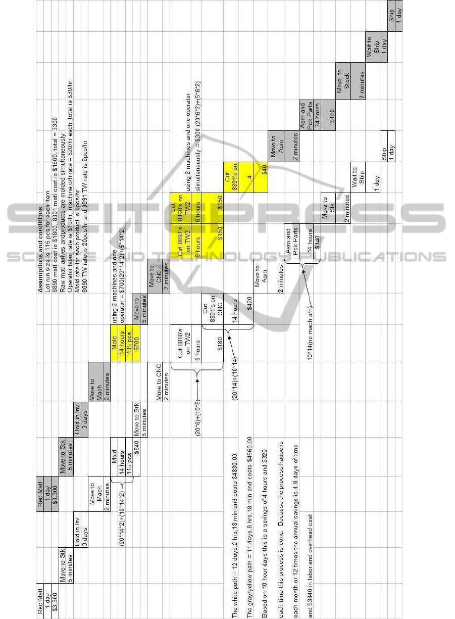
Figure 1: Process Mapping for Two Products (Product A + White Path and Product B = Grey + Yellow Path.
ICINCO 2012 - 9th International Conference on Informatics in Control, Automation and Robotics
526
