
On the Temperature Control for a Test Case Short Pipe Network
Central Heating System
Nikolaos D. Kouvakas and Fotis N. Koumboulis
Halkis Institute of Technology, Department of Automation, 34400 Psahna Evoias, Greece
Keywords: Central Heating Systems, Temperature Control, Autonomous Heating, Dynamic Controllers.
Abstract: In the present paper the mathematical representation of a test case central heating system with a short pipng
network, three radiators and one boiler heating two apartments is developed in the form of a nonlinear
model. A linear dynamic controller achieving independent apartment temperature control and being
unaffected from the external temperature is proposed. The controller is developed on the basis of a linear
approximant. The closed loop performance is tested through simulations on the original nonlinear model.
1 INTRODUCTION
The problem of modelling and control of central
heating systems has attracted considerable attention
during the last years (see Cai, 2006; Hansen, 1997;
Koumboulis et al., 2007; Koumboulis et al., 2008a
and b; Koumboulis et al., 2009a,b and c;
Koumboulis and Kouvakas, 2010; Mendi et al.,
2002; Morel et al., 2001; Zaheer-Uddin et al., 1994;
Zanobini et al., 1998 and the references therein).
Significant attention has also been given to the
modelling of core components of central heating
systems as well as to the application of different
control techniques to regulate the performance
variables. These techniques range from classical and
metaheuristic controllers, fuzzy control schemes,
adaptive controllers, optimal controllers to multi
delay dynamic controllers satisfying transfer matrix
design requirements. In the present paper the
mathematical representation of a test case short pipe
network central heating system including two
apartments is presented in the form of a nonlinear
model. The first apartment has one room while the
second is considered to have two rooms. The system
consists of a short piping network, three radiators, a
boiler and three rooms. The main difference between
the present model and those in Koumboulis et al.,
(2007), Koumboulis et al., (2008a and b),
Koumboulis, Kouvakas and Paraskevopoulos
(2009a-c), and Koumboulis and Kouvakas (2010) is
the length of the pipes. The transport delays are
small and so they do not significantly to influence
the behavior of the plant. Thus, the present
mathematical representation does not incorporate
time delays. Furthermore, the first and the second
room of the second apartment are coupled via direct
heat exchange. A linear dynamic controller
achieving independent apartment temperature
control and being unaffected from the external
temperature is proposed. The controller is developed
on the basis of a linear approximant. The closed loop
performance is examined through simulations on the
original nonlinear model.
2 MODEL OF THE SYSTEM
In the present section the mathematical model of the
test case central heating system, will be presented. It
is similar to that proposed in Koumboulis et al.,
(2007), Koumboulis et al., (2008a and b),
Koumboulis et al., (2009a, b and c), and
Koumboulis and Kouvakas (2010). The system
consists of the piping network, three radiators, a
boiler and three rooms. In each room one of the
radiators is installed. The main difference between
the model developed here as compared to those
presented in Koumboulis et al., (2007), Koumboulis
et al., (2008a and b), Koumboulis et al., (2009a-c),
and Koumboulis and Kouvakas (2010) is that small
length pipes are used. Thus, the transport delays are
small and so they can be neglected. Furthermore, the
two rooms of the second apartment are considered to
be coupled via direct heat exchange. Let
1i
1
622
D. Kouvakas N. and N. Koumboulis F..
On the Temperature Control for a Test Case Short Pipe Network Central Heating System.
DOI: 10.5220/0004048506220627
In Proceedings of the 9th International Conference on Informatics in Control, Automation and Robotics (ICINCO-2012), pages 622-627
ISBN: 978-989-8565-21-1
Copyright
c
2012 SCITEPRESS (Science and Technology Publications, Lda.)

corresponds to the room of the first apartment, while
2i
2
and
3i 3
correspond to the two rooms of the
second apartment. Using the results presented in the
aforementioned papers, the nonlinear dynamic
model of the process can be computed to be in the
following general nonlinear form:
,,,Exuxt Fxu
,
,
xu
,
xt
F
(1a)
yt Cxt
C
xt
,
tLxt
t
xt
L
x
(1b,c)
where
123456789
x xxxxxxxxx
x
12
12
x
x
12
10 11 12 13 14 15 16
xxxxxxx
1 2 3 1,1 2,1 1,2 2,2 1,3 2,3
qqqT T T T T T
q
12
q
12
qq
12
,1 ,1 ,2 ,2 ,3 ,3
T
br fr f r f
TT TT T T T
T
12345
T
uuuuuu
T
T
12345
12345
uuuuu
1234234
123
,,,
T
burner fv fv fv
QPkkk
T
kk
QPkk
123
fv fv
22
2
2
2
fv f
fv
kk
fv ff
1
burner f v
1
,
1
Q
burner f v
QPkk
burner f vf
1234 ,1 ,2 ,3
TT
out out out e
TTTT
TT
T
TT
TT
T
T
,3
e
,3
e
3
TT
3
3
,,
,1 ,2,1
1234
121
TT
T
122
12
1
2
1234
T
and where
1
q
,
2
q
and
3
q
are the volumetric flow -
rates in the radiators of the first, second and third
rooms respectively,
,ji
T
is the
th
j
section temperature
of the radiator placed in the
th
i
room,
b
T
is the
boiler effluent temperature,
,ri
T
and
,fi
T
are the
ambient air and floor temperatures of the
th
i
room,
burner
Q
is the energy supply to the boiler,
P
P
is the
pressure applied to the pipe network by the pump,
,
i
fv
k
is the pressure drop coefficient of the
th
i
valve,
,out i
T
is the external temperature of the
th
i
room and
e
T
is the boiler room temperature. Note that
burner
Q
,
P
P
and
,
i
fv
k
are actuatable inputs while
,out i
T
and
e
T
are measurable disturbances. Note that
yt
and
t
t
are the performance and measurable output
vectors, respectively, while
L
and
316
C
3
3
1
6
. Their
nonzero elements are
1,15
1c
1
,
2,11
0.5c 0.
5
,
2,13
0.5c
0
.
5
,
3,11
1c
1
,
3,13
1c
1
,
1,11
1l
1
,
2,13
1l
1
and
3,15
1l
1
.
The nonzero elements of
E
and
F
are computed to
be:
2
1,1
1
8, Ldexu
1
8
L
Ld
2
,
2
1,2
1
16, Ldexu
2
1
16
L
Ld
2
2,1
1
8, Ldexu
1
8
L
Ld
2
,
2
2,3
1
16, Ldexu
2
1
16
L
Ld
2
3,2
1
8, Ldexu
1
8
L
Ld
2
,
2
3,3
1
8, Ldexu
1
8
L
Ld
2
5
1,
2
3
2
3
,
,
46
r
r
e
Lu
L
dd
xu
xdd
L
6
5
5
u
6
L
6
L
6
6
L
6
3
,
xd
d
3
,
xd
r
d
r
dd
d
dd
2
d
d
2
d
d
4
r
d
2
2
d
2
4
2,
2
2
2
2
,
,
44
r
r
e
Lu
L
dd
xu
xdd
4
L
4
4
4
u
4
4
4
L
4
4
4
L
4
4
4
L
4
2
,
xdd
2
,
xd
r
d
r
dd
d
dd
2
d
d
2
d
d
4
r
d
2
2
d
2
3
3,
2
1
2
1
,
,
42
r
r
e
Lu
L
dd
xu
xdd
L
2
3
3
u
2
L
2
L
2
2
L
2
1
,
xdd
1
,
xd
r
d
r
dd
d
dd
2
d
d
2
d
d
4
r
d
2
2
d
2
4,4
,1exu
1
,
5,5
,1exu
1
,
6,6
,1exu
1
7,7
,1exu 1
,
8,8
,1exu
1
,
9,9
,1exu
1
10,10
,1exu
1
,
11,11
,1exu
1
,
12,12
,1exu1
13,13
,1exu
1
,
14,14
,1exu1
,
15,15
,1exu1
16,16
,1exu
1
27 5 39 510,1
, xx x xx xexu x
5395
53
95
xx
xx
53
9
5
7
2
7
x
7
2
x
2
x
x
2
2
x
2
15 7 39 710,2
, xx x xx xexu x
7397
7397
xx
xx
73
9
73
5
1
5
x
5
1
x
1
x
x
1
1
x
1
15 9 27 910,3
, xx x xx xexu x
9279
92
79
xx
xx
92
7
92
5
1
5
x
5
1
x
1
x
x
1
1
x
1
11
112310,5
,1eaxauxxxx
123
1
xx
12
11
1
ax
a
1
11
212310,7
,1eaxaxxxxu
123
axxx
1212
11
2
1
ax
2
1
11
312310,9
,1eaxaxxxxu
123
axxx
1212
11
3
1
ax
3
1
31,1 3
2,,,,,,
pprr
fxLd fxLdfxu
3
xL
,
3
3
,
3
p
p
2
p
f
p
prr
3
fxLd
,
3
prr
3
,
3
23 123
2,,2 ,,
pp
f x xLd f x x xLd
123
p
3
xLd f x x xLd
123
,, 2 ,,,, 2 ,
3123312
3
3
2
35 3 2
,,
vt
fxud Kx u
2
3
2
Kx
u
2
3
22,1 2 3
,, , , 2 ,,
prr p
fxLd fx xfu dxL
23
,,
3
rr p
Ld f x x
2
,, 2,2
2
rr p
,,,
d
L
2
x
2
,
2
,
p
f
p
2
123 24 2 2
2,,,,
pvt
fx x xLd fxud Kx u
2
2
2
2
pvt
123
24
fx x xLd fxud Kx
u
2
2
2
2
,
,,
,
,
,
123 242423 2
p
123
24
123 242423 2
2
3,1 1 1 3 1
,,,, , ,
prrv t
fxLd fxudfu Kxx
2
1
13
13
Ld f xud
13
13
,,
,,
3
3
13
13
3
3
Kx
1
1
x
1
,
1
p
f
p
123 2
2,,
p
fx x xLd u
123
2
2
p
fx
xxLdu
123
2
,
,
12323
p
11
1144,
1
60 60 1,,
nn
q
fxu NHx x
C
C
60
1
60
1
0
1
6
0
C
1
n
1
1
4
4
x
1
1
510 411 0
n
xx xx
5
x
5
1
11 0
n
x
10
x
10
4
4
xx
4
4
15,1
1
45
,,
q
CNfxu Hxx x
5
x
C
1
1
H
H
N
H
N
1
4
q
1
4
q
Hx x
1
4
H
N
H
N
N
N
H
N
1
1
511 0
60
n
n
xx
1
511 0
60
n
xx
5
1
n
x
On the Temperature Control for a Test Case Short Pipe Network Central Heating System
623

11
2166,
1
60 6,1,0
nn
q
NH xf
C
xxu
C
6
1
0
6
1
0
0
1
60
C
1
n
1
1
6
6
1
x
1
710 613 0
n
xx xx
1
13 0
n
x
710
xx
710
6
6
xx
66
27,1 7
1
6
,,
q
Nfxu xCHxx
7
x
C
1
H
H
N
H
N
2
q
2
q
Hx x
2
H
N
H
NN
N
H
N
1
1
713 0
60
n
n
xx
1
713 0
6
0
n
xx
7
1
n
x
11
3188,
1
60 60 1,,
nn
q
fxu NHx x
C
C
60
1
60
1
0
1
60
C
1
n
1
1
8
8
x
1
1
910 815 0
n
xx xx
9
x
9
1
15 0
n
x
10
x
10
8
8
xx
8
8
39,1 9
1
8
,,
q
Nfxu xCHxx
9
x
C
1
H
H
N
H
N
3
q
3
q
Hx x
3
H
N
H
N
N
N
H
N
1
1
915 0
60
n
n
xx
1
915 0
60
n
xx
9
1
n
x
11 1 2 3 ,max10,1
,,
w
au x xxu xfT
1
x
1
1
u
1
1
a
1
23,max
x
x
T
15 10 4 27 10
11
j
axax ax xax ax
1
1
5
5
ax
5
1
1
10
42
10
10
10
42
42
42
1
1
7
7
7
7
0
1
1
ax
a
439 104,max
1
w
xax ax T
439 104,max
ax T
910410 4
a
x
1
39
39
xax
39
3
12310
xxxx
23
10
x
xx
2323
21 1 2 3 ,max
1
ww
aau C x x x T
1
1
1123,max
1
1
1
max
T
aa
u
1
1
1
C
x
1
2
2
aau
2
3
23
23
23
x
x
232
15 27 39
xx xx xx
15 27 39
xx xx xx
15 27 3
5273
21 1 2 3 ,maxww
aa u C x x x T
T
C
21
21
aa u
21
23,max
23
1
1
23ma
x
23
x
xT
23
23
1
1
C
x
1
123,max
/1
bw
aCxxxT
C T
1
123
,ma
x
b
123
max
bw
123
Cx x xT
1
b
123
23
11
11 12 1,121,1
60,, 60
nn
out
NR x x Rfxu
11 12 1,
2
out
Rx xR
11 12 112 1
t
60
1
n
1
1
n
60
NR
1
60
NR
1
11 1 1,2
60
n
f
RNxR
11
n
Nx
1
11
60
n
11
,2
R
11
1
1
11 13
60
n
out
RNxx
11 13
n
Nx x
1
11
60
n
11
411 511 01,2
1000
nn
xx xx R
11
nn
1
R
11
x
xxx
R
4
x
4
x
11 5 11 0 1
,2
xxx
R
11 5
11 0 1
11 5
1
x
xx
R
1,2
/( )
rfout
NC R R R
11
13 14 1,123,1
60,, 60
nn
out
NR x x Rfxu
13 14
1,
2
out
Rx xR
13 14 1
14 1
t
60
1
n
1
1
n
60
NR
1
60
NR
1
13 2 1,2
60
n
f
RNxR
13
n
N
x
1
13
60
n
21,2
R
21
1
1
11 13
60
n
out
RNxx
13
x
11
613 713 01,2
1000
nn
xx xx R
11
nn
1
R
11
x
x
xx
R
6
x
6
x
13 7 13 0 1,2
xxx
R
13 7
13 0 1
13 7
1
x
xx
R
1,2
/
rfout
NC R R R
11
1,1 3165
1
60 60,,
nn
rout
Nxf
NC R
xu
NC
1
n
1
1
1
6
60
n
60
Nx
3
1
R
1
NC
11
816 916 0
1000
nn
out
Rxx xx
x
x
8
x
8
x
1
n
1
x
1
x
16
x
16
x
9
x
9
x
1
6
1
n
1
x
x
0
2
12,1
11 1
,,
ff
x
xu
x
R
f
C
R
C
R
11
x
R
C
2
1
1
x
,
4
14,1
13 1
,,
ff
x
xu
x
R
f
C
R
C
R
13
x
R
C
4
1
1
x
6
16,1
15 1
,,
ff
x
xu
x
R
f
C
R
C
R
15
x
R
C
6
1
1
x
,
,qd
,
qd
,
12
, 1 Re , , Re ,f qd w qd f qd w qd
f
d
1
d
dfd
R
R
1
fq q fq q
1
,
d
e,
fq
1
,1
2
2
,
2
Re , , ReRe , ,
2
4
Re ,
q
qd
d
d
4
q
d
,
1
, =64/Re ,fqd qd
0.25
21
,/Re,fqd qd
,
,
1
/
1
/
/
Re
1
12
0.5 tanh 0.5wx x
0.
5t
an
h
0
.
5ta
n
h
12
0
.5
12
1
252
,, , 8
p
fqLd qd L dq
Ldq
252
d
q
25
5
qd
,8
422
,, 8
v
fqud d qu
qu
22
qu
22
d
8
4
4
2
2
,
12
123
1axxa xx
x
123
1
x
1
xx
22
12
a
a
1
1
where
,
,
ij
exu
and
,1
,,
i
fxu
are the
,ij
and
,1i
elements of
,Exu
and
,,Fxu
, while
d
and
r
d
are the pipe and radiators diameter respectively,
L
denotes the lengths of the pipes connecting the
pump to the first valve, the first valve to the second
valve, the second valve to the third valve,
r
L
denotes the equivalent length of the radiators
respectively;
1
1
,
1
1
and
2
2
are flow condition
parameters,
t
K
is the turbulent pressure drop factor
caused to the entrance of the radiators,
w
C
and are
the thermal capacity and density of the water
respectively,
C
and
0
0
are the heat capacity of the
water/radiator material and the nominal heat of the
radiator,
1
n
and are radiator model parameters,
N
is the number of sections of each radiation,
b
C
is
the thermal capacity of the boiler,
j
a
is the rate of
heat loss from the boiler jacket to the environment,
,maxw
T
is the maximum boiler effluent temperature,
1
a
and
2
a
are parameters connecting the boiler
lumped temperature to the boiler efficiency,
a
is
coefficient connecting the lumped water temperature
of the boiler to the inlet and outlet temperature,
f
C
ICINCO 2012 - 9th International Conference on Informatics in Control, Automation and Robotics
624

and
r
C
are the floor and room thermal capacities
respectively,
f
R
,
out
R
and
1,2
R
are the thermal
resistances between the room and the floor, the room
and the environment and the first and second room
respectively. From model (1) it is observed that the
performance variables are the temperature of the
room of the first apartment (1
st
output), the average
of the temperatures of the two rooms of the second
apartment (2
nd
output) and the difference between
the temperatures of the two rooms of the second
apartment (3
rd
output).
The linear approximant of the central heating
system (1) is computed to be of the form
xt Axt But D t
x
xt
B
ut
D
t
xt
A
(2a)
yt Cxt
yt
Cx
t
,
tLxt
t
L
xt
(2b,c)
After extensive computational experiments for a
wide range of inputs and disturbances, it has been
observed that the model (2) is an accurate
approximant of the original nonlinear model (1). In
the next section, the linear approximant will be used
to develop a linear controller performing satisfactory
to both the linear and the nonlinear model.
3 CONTROLLER DESIGN
Consider the dynamic controller
1
Us K s s
U
s
1
Ks s
1
2
Ks s GsWs
2
Ks
G
sW
s
2
sG
(3)
where
,,Us s s
,
Us
,
,
ss
,
and
Ws
denote the
Laplace transform of
,,ut t t
,,
ut t t
,,
and
wt
(external command). Clearly,
53
1
Ks s
5
53
5
5
3
5
5
3
5
5
s
,
54
2
Ks s
5
54
5
5
4
5
5
4
5
5
s
and
52
Gs s
5
52
5
5
2
5
5
2
5
5
s
. The
design goal will be that of independent control of the
main performance variables (i.e. the temperature of
the room of the 1
st
apartment and the average
temperature of the two rooms of the second
apartment) with simultaneous disturbance rejection.
Furthermore it is required to keep the difference
between the first and second room temperatures
enough small. If the controller (3) is applied to the
approximant (2), the design goal is formulated as a
block decoupling with simultaneous disturbance
rejection requirement, i.e.
1,1
2,2
3,2
0
0
0
C
Hs
Ps H s
Hs
0
Hs
1,1
11
0
Hs
11
1,1
Hs
0
2,2
22
Hs
22
0
0
0
0
H
,
3,2
0
Hs
32
0
Hs
,
34
0
D
Ps
3
0
34
(4a,b)
where
C
Ps
and
D
Ps
are the transfer matrices
mapping the external commands and the
disturbances to the performance outputs,
respectively, and where
1,1
Hs
,
2,2
Hs
and
3,2
Hs
are appropriate transfer functions.
A set of controller matrices satisfying the design
goal is:
†
16 1 C
Gs sI K sQs P sP s
†
†
PP
†
sI K s Q
C
C
sP sPs
†
C
16 1
Q
16 1
sI K s Q
16 1
(5a)
†
2161 d
Ks sI KsQsPsPs
†
†
sI K s Q s P s P s
†
16
1
d
Q
16 1
d
sI K s Q s P s P s
†
16 116
d
1
51 1d
Ps I K sQs K sQ s
1
Ps
KQ
K
IKsQ
1
d
Q
1
d
KsQ
s
1
d
K
51
51
IKsQ
s
511
(5b)
1
Ks
is arbitrary and proper
(5c)
where
1
16
Qs LsI A B
16
LsI A B
16
1
B
,
1
16d
Qs LsI A D
16
LsI A D
16
1
D
1
16
Ps CsI A B
16
CsI A B
16
1
B
,
1
16d
Ps CsI A D
16
CsI A
D
16
1
D
1
†
T
TT
Ps P s
Ps Ps
1
T
1
1
†
T
T
T
T
†
PP
†
T
T
T
T
Ps
Ps
†
s
P
T
T
P
P
P
P
P
Ps
P
P
P
Ps
Ps
T
T
T
P
P
P
P
Ps
P
P
P
Ps
Ps
P
P
and
Ps
Ps
is a
25
5
rational matrix preserving the
invertibility of
TT
Ps Ps
T
T
P
P
Ps P
Ps P
Ps P
T
T
P
Ps
Ps
Ps
. Choose
6
1
1,1 1,
1
() 1
j
j
Hs s
j
1
6
6
1
,
1
1
j
1
1
1,
j
,
6
1
2,2 2,
1
() 1
j
j
Hs s
1
j
1
6
6
2,
1
2
j
2
1
2,
j
6
1
3,2 3,
1
1
j
j
Hs s
1
j
1
6
6
3,
1
j
s
3
j
1
3,
j
Let
5mL
5
m
,
2m
r
L
2
m
,
0.015 md
0.
01
5
m
m
0.0096153 m
r
d
0.
00
96
1
m
,
3
971.81 Kgr m
81
9
71.
8
3
K
g
3
Kgr m
,
0.0003547 Pa s
0
354
7
0.00
0
Pa s
,
1
=0.00819
1
=0
.0
08
,
2
2300
2
0
23
00
2N
2
,
0
0.395 W
0
0.
39
5
W
,
0
0
,
0.00002
t
K
0
.
0000
2
,
36 KJ KC 36
K
KJ
K
KJ
,
1
1.25n
1
.2
5
,
29a
29
,
1
1a
1
,
2
0.12a
0
.
12
,
5.06 W K
j
a
5
.06
WK
W
WK
W
,
On the Temperature Control for a Test Case Short Pipe Network Central Heating System
625

2175525 J K
f
C 21
7
552
J
K
J
K
,
43268 J K
r
C 4
3
2
68
JK
J
J
K
J
,
0.01614 K W
out
R
0
.0161
4
KW
KW
,
0.0333 K W
f
R 0.0333
KW
KW
,
12
0.03 K WR
0
.
03
W
K
W
K
,
,max
100 °C
w
T 1
00
°C
°C
4170 J K Kgr
w
C
4170
JK Kgr
g
JK Kgr
J
,
42400 J K
b
C 42
40
0
JK
J
J
K
J
,
1
0.316
1
6
0.
31
6
1
2000 Wu 2000
W
W
,
2
2000 Pau
2
000
Pa
P
,
3
300u
300
,
4
300u
3
00
,
5
300u
300
,
1234
15 °C
1
23
4
15
°C
C
°C
1
lt hr57.58x
57
.58
t
h
l
t
hr
l
,
2
lt hr51.18x
5
1.1
8
t
h
l
t
hr
l
3
lt hr49.19x
49
.1
9
t
h
l
thr
l
,
4
92. 2 C1x
92
.2
1
C
5
88. 7 C6x
88
.7
C
,
6
91. 9 C6x
91. 9
C
,
7
87. 6 C8x
87
.6
C
8
91. 3 C5x
91
.3
C
,
9
87. 7 C5x
87
.7
C
,
10
95.79 Cx 95.
79
C
11
22.41 Cx
2
2.
4
1
C
,
12
22.41 Cx
2
2.
41
C
13
22.37 Cx 22.3
7
C
,
14
22.37 Cx 22.3
7
C
15
22.33 Cx
22
.3
3
C
,
16
22.33 Cx
22
.3
3
C
1,1
500
1,1
0
50
0
,
1,2
525
1,2
5
5
2
5
,
1,3
550
1,3
0
5
5
0
,
1,4
575
1
,4
5
5
75
1,5
600
1
,
5
0
600
,
1,6
625
1
,6
5
62
5
,
2,1
500
2
,
1
0
500
,
2,2
525
2
,
2
5
525
2,3
550
2
,
3
0
550
,
2,4
575
2,
4
5
5
7
5
,
2,5
600
2
,
5
0
6
0
0
,
2,6
625
2
,
6
5
625
3,1
500
3
,
1
0
500
,
3,2
525
3
,
2
5
52
5
,
3,3
550
3,3
0
550
,
3,4
575
3,4
5
57
5
3,5
600
3
,
5
0
6
0
0
,
3,6
625
3
,
6
5
625
,
0.009
09
0
.
0
Selecting
000
1.08
0.9
91.
28 0.7
062 0
06
00
Ps
1
062 0
0
000
09
28
.9
28
.9
28
1
.
08
9
108
9
0
0
0
0
0.
7
0
6
Ps
0
0.
0.
1
3954.21 7278.84 3148.84
8990.94 1246.73 6284.94
1435.48 3632.79 869.98
8654.17 9593.39 9528.82
7409.89 451.43 8273.09
Ks
7278.84 3148.84
7278.84 3148.84
8990 94 1246 73 6284 94
8990 94 1246 73 6284 94
8363279 86998
8363279 86998
8990.94 1246.73 6284.94
3954.2
1
3954.2
1
83
63
2.
79
86
9.
98
7 9593 39 9528 82
7 9593.39 9528.82
79
59
3.
39
95
28
.8
2
273
.
09
27
3
09
7278.84
7278.84
1246 73
1246 73
1246
.
73
8
8
48
48
14
35
14
35
8
.4
8
14
35
8654 17
8654.17
86
54
.1
7
9 451
.
43 82
74
09
8
94
51
4
38
2
7409
.
89
7409 89
the controller can be computed. It is pointed out that
the resulting closed loop system is asymptotically
stable.
To demonstrate the performance of the derived
controller, we apply the external commands
1
0.5 Cwt
0.5
C
,
2
1Cwt
1
C
. The
disturbances are considered to be all equal to
0.002 0.001 0.0005
18
15 2 1 e 2e e
33
tt t
t
t
8
1
2e e
8
0.0005
8
002 0 0
01
2e e
.002 0.001
000
002
t
0.0005
00
01
00
0.001
0.001
0.001
00
01
00
1
1
0
1
1
1
0
0
0
1e
1
e
0.
3
2e e
3
2
ee
3
3
3
1
e
3
1
5
2
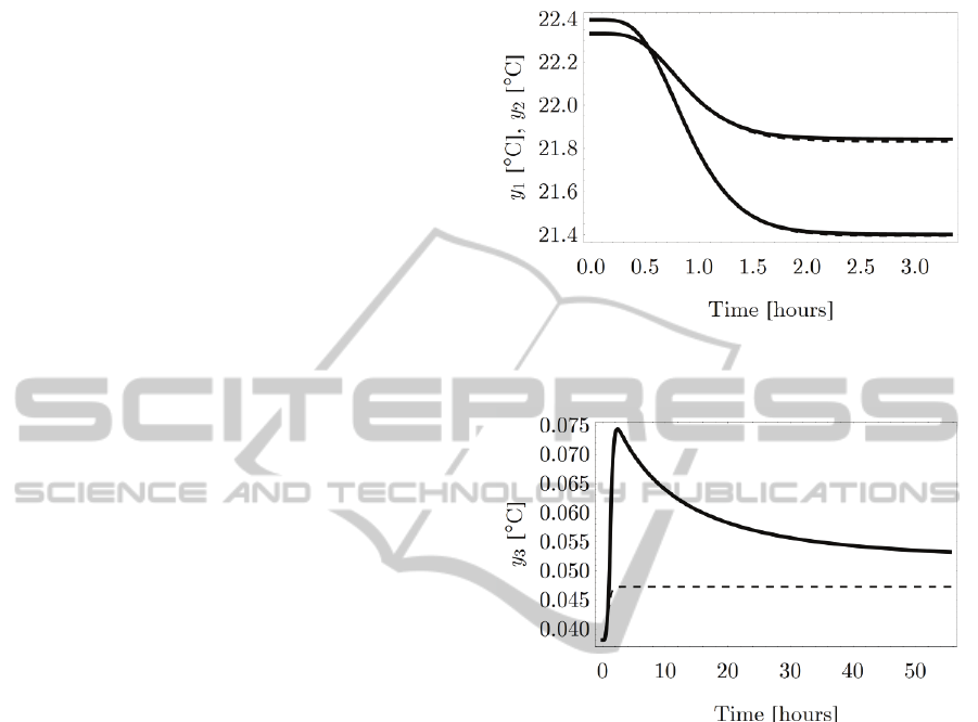
Using the above assumption, the closed loop
responses for the performance variables are
presented in Figures 1 and 2. From Figure 1 it can
readily be observed that the apartment temperatures
follow accurately the reference signals with the
respective curves being practically identical. The
maximum error throughout the simulation was for
the first performance variable about
0.012 C
C
while
for the second performance variable it was about
0.007 C
C
. Eventhough, in the third performance
variable (see Figure 2) the error is significantly
larger, it remains extremely small suggesting that the
variation cannot be sensed by the occupants of the
rooms. Before closing the section it mentioned that
state variables and the actuatable input variables
remain within acceptable limits.
4 CONCLUSIONS
The mathematical model of a test case central
heating system with a short piping network, three
radiators, a boiler and three rooms in two apartments
has been developed. Based upon the linear
approximant of the nonlinear model a dynamic
controller, achieving independent control between
the two apartment temperatures together with
rejection of the influence of the external
temperatures and small differences between the
temperatures of the rooms of the second apartment,
has been derived. The performance of the controller
has been examined through simulations on the
nonlinear model of the plant.
REFERENCES
Cai, W., 2006. Nonlinear Dynamics of Thermal-Hydraulic
Networks, PhD Dissertation, University of Notre
Dame.
Hansen, L. H., 1997. Stochastic Modeling of Central
Heating Systems, PhD Dissertation, Technical
University of Denmark.
Koumboulis, F. N., Kouvakas, N. D., Paraskevopoulos, P.
N., 2007. Modeling and Control of a Neutral Time
Delay Test Case Central Heating System, In
Proceedings of the 6th WSEAS International
Conference on Circuits, Systems, Electronics, Control
& Signal Processing (CSECS'07), pp.289-297,
December 29-31, Cairo, Egypt.
Koumboulis, F. N., Kouvakas, N. D., Paraskevopoulos,
P.N., 2008. Analytic Modeling and Metaheuristic PID
Control of a Neutral Time Delay Test Case Central
Heating System, In WSEAS Transactions on Systems
and Control, vol. 3, no. 11, pp. 967-981.
ICINCO 2012 - 9th International Conference on Informatics in Control, Automation and Robotics
626
Koumboulis, F. N., Kouvakas, N. D., Paraskevopoulos, P.
N., 2008. Dynamic Disturbance Rejection Controllers
for Neutral Time Delay Systems with application to a
Central Heating System, In Proceedings of the
International Conference on Modelling, Identification
and Control (ICMIC 2008), June 29 - July 2,
Shanghai, China.
Koumboulis, F. N., Kouvakas, N. D., Paraskevopoulos, P.
N., 2009. Dynamic disturbance rejection controllers
for neutral time delay systems with application to a
central heating system, In Science in China Series F:
Information Sciences, vol. 52, no. 7, pp. 1084 – 1094.
Koumboulis, F. N., Kouvakas, N. D., Paraskevopoulos, P.
N., 2009. Linear approximant-based metaheuristic
proportional-integral-derivative controller for a neutral
time delay central heating system, In Proceedings of
the IMechE Part I: Journal of Systems and Control
Engineering, vol. 223, pp. 605-618.
Koumboulis, F. N., Kouvakas, N. D., Paraskevopoulos, P.
N., 2009. On the Morgan's Problem for Neutral Time
Delay Systems via Dynamic Controllers with
application to a Test Case Central Heating System, In
Proceedings 3rd IEEE Multi-conference on Systems
and Control (MSC 2009), July 8-10, Saint Petersburg,
Russia.
Koumboulis, F. N., Kouvakas, N. D., 2010. Approximate
Temperature Control of a Neutral Time Delay Central
Heating System via a Two Term Disturbance
Compensator, In Proceedings of the 15th International
Conference on Emerging Technologies and Factory
Automation, September 13-16, Bilbao, Spain.
Mendi, F., Boran, K. and Kulekci, M. K., 2002. Fuzzy
Controlled Central Heating System, In International
Journal of Energy Research, vol. 26, no. 15, pp. 1313-
1322.
Morel, N., Bauer, M., El-Khoury, M. and Krauss, J., 2001.
NEUROBAT: A Predictive and Adaptive Heating
Control System Using Artificial Neural Networks, In
International Journal of Solar Energy, vol. 21, pp.
161-201.
Zaheer-Uddin, M., Zheny, G. R. and Cho, S.-H., 1994.
Optimal Operation of an Embedded-Piping Floor
Heating System with Control Input Constrains, In
Energy Conversion and Management, vol. 38, no. 7,
pp. 713-725.
Zanobini, A., Luculano, G. and Papini, A., 1998. Central
Heating Control: a New Technique to Gauge Room
Temperature, In Proceedings of the IEEE
Instrumentation and Measurement Technology
Conference, May 18-21, St. Paul, USA
APPENDIX
Figure 1: Closed loop responses for
1
y
and
2
y
(continuous -
1
y
and
2
y
, dashed – reference).
Figure 2: Closed loop response for
3
y
(continuous -
3
y
,
dashed – reference).
1
y
2
y
On the Temperature Control for a Test Case Short Pipe Network Central Heating System
627
