
Plant Level Framework for Material Flow in a Nuclear Reprocessing
Facility
Hyo Jik Lee, Won Il Ko and Han Soo Lee
Korea Atomic Energy Research Institute, Daedeok-daero 989-111, Yuseong, Daejeon, 305-353, Republic of Korea
Keywords: Plant Level Framework, Spent Nuclear Fuel Reprocessing, Pyroprocess, Mass Balance, Discrete Event
Dynamic System.
Abstract: A plant level framework has been developed for a nuclear recycling facility. A plant level model generally
consists of multi-tiered models. The bottommost tier is a unit process model regarding electro-chemical
phenomenon. The middle tier is an operation model regarding mechanical handling of the process
equipment. The topmost tier is a systemic integration in the level of the plant. Even though a unit process
model is fundamental to build higher tier models it takes time to make a model with high fidelity. Therefore,
a different strategy for a plant level model building is suggested in this study. One of the important issues
that nuclear recycling process must consider is dynamic material flow, which could be done with the help of
a unit process model. However, from plant level aspect, it can be simply obtained from mass balance sheet
rather than understanding of electro-chemical behavior during process time. A plant level framework was
suggested to be able to include dynamic material flow even without a unit process model. Thus, a more
reliable unit process model can be added later selectively. The characteristic of the current framework was
addressed and evaluated for further improvement. The current version of the plant-level-framework could
provide many unforeseeable results which are difficult to obtain by intuition. Nevertheless, the next version
will include more function to provide various analyses linked with other nuclear related codes.
1 INTRODUCTION
Next generation nuclear fuel cycles require
innovative features such as an environmental load
reduction, safety, efficient recycling of resources,
nuclear proliferation resistance, economics, and so
on. From these viewpoints, a pyrometallurgical
processing of spent fuel is now considered as one of
the most promising options for future nuclear cycles
in Korea (Kim, 2006). KAERI has been developing
pyroprocess technologies, which could reduce the
increasing amount of spent nuclear fuel and
dramatically decrease the disposal load, through
recycling and destroying toxic waste such as the
long-life fission products in spent nuclear fuels (You,
2007).
Pyroprocessing technology has not been fully
demonstrated in terms of comercialization and
technology maturity. In order to navigate the right
direction of pyroprocessing technology development,
demonstration in an integrated facility is centainly a
tangible solution but is too costly and time
consuming to construct a fully integrated facility
including all unit process and remote handling
equipment. Therefore, technolgoy assessment and
breakthrough by modeling and simulation would be
preferable. Plant modeling and simulations are now
widespread among the manufacturing, semi-
conductor, steel and refinery industries. However,
they focus on layouts, assembling, automation and
remote control of the process flow.
Currently, there is niether commercialized nor
integrated pyroprocessing facility around the world.
KAERI is constructing an integrated demonstration
facility and thus expect to contribute to boost up
pyroprocessing technology and step toward
realization of spent nuclear fuel recyling.
Nevertheless, pyroprocessing technology is
confronted by many problems which are awaiting
solutions at the moment.
Expected potential benefits of modeling and
simulation in the field of nuclear reprocessing
system include the following: reduced cost of
process and facility development, optimized system
designs and reduce risk of material diversion.
Actually, modeling and simulation enhance
377
Jik Lee H., Il Ko W. and Soo Lee H..
Plant Level Framework for Material Flow in a Nuclear Reprocessing Facility.
DOI: 10.5220/0004056703770383
In Proceedings of the 2nd International Conference on Simulation and Modeling Methodologies, Technologies and Applications (SIMULTECH-2012),
pages 377-383
ISBN: 978-989-8565-20-4
Copyright
c
2012 SCITEPRESS (Science and Technology Publications, Lda.)

understanding of known systems, provide qualitative
and quantitative insights and guidance for
experimental work and produce qunatitative results
that replace difficult, dangerous or expensive
experiments (DePaoli, 2011).
The pyroprocessing contains various unit
processes and various types of nuclear materials that
flow in and out of those unit processes. It is a batch
type process in overall terms, i.e., reciept and
shipment of material among unit process, however,
unit process itself features continuous chemical or
electro-chemical process. Unit process may have a
different batch capacity and different processing
time. Also, there is feedback of output material on a
unit process into a prior unit process. In addition,
nuclear elements may take different routes as the
process goes on. Due to this complexity, it is
difficult to understand the dynamic behaviors of the
material flow in the pyroprocess. With this
background, this study was undertaken. Simple
material flow in the pyroprocess can be easily
understood by static mass balance. However, a
simple material flow based on the static mass
balance cannot give insight into any dynamic
behavior of the material flow because it cannot take
into account changes according to time and event.
An EXCEL-like software is widely used to
establish the static mass balance of the overall
process but it is very restrictive to implement a
dynamic material flow in the pyroprocess. In this
study, a modeling and simulation tool for discrete
event dynamic system (DES), ExtendSim was
utilized for the plant level framework of a dynamic
material flow. The pyroprocess was modeled as DES
in this work and then a dynamic material flow was
simulated under the framework.
2 R&D STATUS
2.1 The U.S.
Motivated by the challenges and needs in nuclear
energy systems that can be addressed bymodeling
and simulation, the Office of Nuclear Energy of the
U.S. Department of Energy hasarticulated a vision
for a Nuclear Energy Advanced Modeling and
Simulation (NEAMS) program.NEAMS is aimed
toward building on the success of recent programs in
advanced scientificcomputing, namely, ASCI and
SciDAC, with a focus on very different challenges.
Thesechallenges include the need for nuclear energy
systems to be licensed by regulators andmoving
advanced technologies out of the research
environment and into the hands of theengineers who
will design, build, and operate the new nuclear
energy systems. NEAMS will provide a
comprehensive solution and is organized into the
following five elements:
• Integrated Performance and Safety Codes (IPSC)
end-to-end codes to understand the detailed,
integrated performance of new nuclear systems
including the following: Nuclear Fuels, Reactor
Core & Safety, Separations and Safeguards, Waste
Forms and Near-Field Repositories.
• Fundamental Methods and Models
• Verification, Validation, and Uncertainty
Quantification
• Capability Transfer Enabling Computational
Technologies
Through the NEAMS-IPSC, the U.S. is devoting to
develop reprocessing plant level toolkit named
RPTk (Reprocessing Plant Toolkit), which uses open
source platform to accormodate legarcy codes
accross the U.S. (McCaskey, 2011). RPTk
implements a data flow architecture that is the
source of the system’s extensibility and scalability.
Data flows through physicochemical modules
sequentially, with each module importing data,
evolving it, and exporting the updated data to the
next downstream module. This is accomplished
through various architectural abstractions designed
to give RPTk true plug-and-play capabilities.
2.2 Japan
A decade ago, Japan developed an analysis code
(Okamura, 2002) using the object-oriented software
ExtendSim for the estimation of material balance for
the system design of the pyrochemical reprocessing
plants consisting of batch processes. This code can
also estimate the radioactivity balance, decay heat
balance and holdup, and easily cope with the
improvement of the process flow, and so on. The
study describes the outline of the code and
estimation of the material balance in the oxide
electrowining reprocessing system under
consideration of the solvent recycling time.
Howerver, it is difficult to find out current activity
with respect to modeling and simulation spent fuel
recyling facility in japan.
2.3 Korea
In order to analyze operational issues in a
pyroprocessing head-end facility, discrete event
modeling approach was applied (Lee et al., 2009).
Also, a code development study on the dynamic
SIMULTECH 2012 - 2nd International Conference on Simulation and Modeling Methodologies, Technologies and
Applications
378

material flow in the integrated pyroprocess was
carried out (Lee et al., 2011) under the discrete event
system environment. This paper addresses the plant
level framework in detail including the previous
dynamic material flow study.
3 REQUIREMENT
3.1 Nuclear Facility
A nuclear facility deals with radioactive material and
the recycling facility can have various types of
material since nuclear spent fuel consists of various
nuclear fissile elements. Specifically, integrated
pyroprocess facility has a lot of unit process
equipment, remote handling device and various
utility, which need to be appropriately maintained
and repaired for machine failure.
Receipt and shipment of nuclear material and
remote operation of process equipment are
considerately designed in terms of safety and
efficiency. Also, safeguards study to prevent nuclear
material diversion is critical issue in design stage.
Current version of plant level framework does not
include safeguards module, but later version will
consider including it.
3.2 Facility Code Requirement
Simulation code for pyroprocessing facility is
required to have the following features:
1. Modularity
Modularity means re-useable code. Some libraries or
blocks can be frequently re-useable within a plant
model. For example, dynamic mass balance
calculation algorithm is needed to calculate
processed quantity in any unit process during
simulation.
2. Flexibility
Flexibility means the code can be modifiable in easy
way. For example, if more reliable unit process has
been built, it can be replaced with old one without
many modifications of code. Also, additional
function or module could be attached in a way that
main framework or top tier model does change
minimally or does not change by taking interface
with additional module into consideration.
3. Database management
Database management is very important issue in
terms of nuclear element management. Recycling
facility starts with spent nuclear fuel having many
element, which changes its form, radioactivity and
amount according to process flow. There are three
types of data as follows: input data, output data, and
log data. Input data are for example, changeable
process conditioning parameters. It influences
simulation results. Output data can be simulation
results related data, for example, product amount,
buffer accumulation and waste generation. Data
logging is important to keep and store time
dependent information, and see and analyze those
after simulation. For example, status of unit process,
operation records, resource utilization and all output
data can be log data.
4. Interface with other platform code
There exist many legacy codes developed in other
software platforms. Specifically, unit process model
has been generally generated by using other
conventional platform such as C/C++, FORTRAN,
and matlab according to modeller’s preference.
Therefore, integration of different codes could be an
issue on plant-level-code development.
5. Reliability enhancement strategy
In order to enhance model and well estimate reality,
model validation must be performed with a lot of
experimental data. Throughout comparison with
various real cases, model could be enhanced.
Therefore, validation can be easily carried out by
visualization of analysis results.
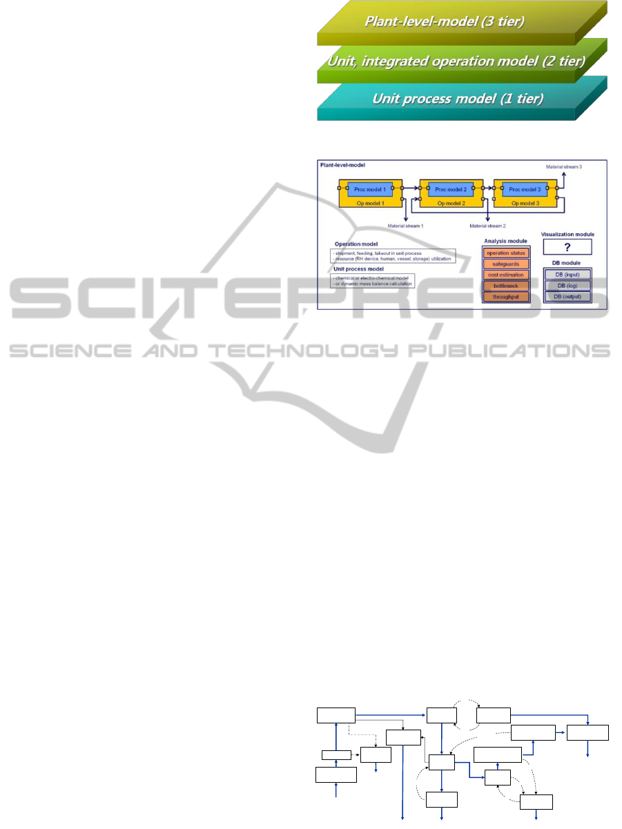
3.3 Plant-level Code Configuration
Plant-level-model includes all lower models together
with various modules. The unit process model is
surrounded by unit operation model describing
feeding and takeout of material in that process and
then material streams among unit process are
completed by integrated operation model which can
describe the shipment of material.
Also, in the integrated modelling stage, resources
such as remote handling device, human, vessel and
storage are allocated to unit process according to
necessity and withdrawn after the task is finished.
All items taken out of and fed into unit process are
treated in the unit of batch capacity of unit process.
If two sequential unit processes have different batch
capacity, the item taken out of the first unit process
has to be changed to meet the batch capacity of the
next unit process. Material streams indicate where
items must flow into and thus connectors and lines
must be designed according to material streams.
Discrete event modelling might handle the above
issues without difficulty. The plant-level-model also
has to include three functions: analysis, database
management and visualization. They could be
modularized and developed in many ways. For
Plant Level Framework for Material Flow in a Nuclear Reprocessing Facility
379
example, DB can be remotely far from ExtendSim
and just linked with ExtendSim.
4 PLANT LEVEL MODEL
4.1 3-tiered Modelling Architecture
In order to build plant-level-model, 3-tiered code
development architecture was invented in KAERI.
The bottom tier is unit process modeling which
includes electro-chemical model influencing output
chemical composition. The middle tier includes unit
and integrated operation model which describes
operation behavior such as feeding, transporting and
other mechanical operations from unit or integrated
process ascpect, resptectively. The top tier is the
plant-level-model, which must have various analysis
modules, and DB module for SNF and isotope
inventory. It also have to show the results,
intuitively through well designed visualization
module.
4.2 Basic Framework
Without reliable unit process model, it is too
difficult to build upper tier model. Currently
electrochemical process is not well described by
model and must be enhanced further. It is alike
wasting time to wait until the reliable unit process
model is built. Furthermore, most part of the middle
and top tier model can be built without the unit
process model. Given feeding material composition
and its amount, unit process model presents
generally output composition of element after
electrochemical reaction. Noticing that expected
values of output composition could be set by target
values in an equilibrium mass balance sheet, the
calculation of dynamic mass balance per batch
operation in unit process might be alternative of unit
process model. Even though equilibrium mass
balance means total input and output mass balance
in each unit process at a certain time, it can be
broken down by unit of each batch operation
capacity of unit process according to each batch time
and it can be made to present dynamic mass balance.
The current version of plant level framework was
tested by using dynamic mass balance calculation
algorithm without unit process model. However, the
framework could selectively include the unit process
model or dynamic mass balance calculation
algorithm when the reliable unit process model is
prepared.
Figure 1: Three tiered code development architecture.
Figure 2: Configuration of plant-level-framework.
4.3 Dynamic Material Flow
Pyroprocess consists of a dozen of unit process and
various material streams among them as shown in
Figure 3. Material streams in pyroprocess are
classified into two categories: nuclear spent fuels
and two kinds of salt (LiCl and LiCl-KCl). First
feeding material of pyroprocess is spent nuclear fuel
from nuclear reactor in the form of assembly and
final product is volatile FP (fission product), metal
waste, ceramic waste, uranium metal ingot and TRU
(transuranium) for fast reactor fuel fabrication.
Every time process proceeds to next step, many
things (processed mass, buffer accumulation, the
number of batch operation, etc.) are changed
according to time. In order to capture such dynamic
characteristic related to material flow, discrete event
based dynamic mass balance calculation (Lee et al.,
2011) is needed in case where a target mass balance
is set by equilibrium state at a specific instance in
time.
Figure 3: Pyroprocess material streams.
U metal ingot
Chopping
Electro-
winning
Salt (LiCl+KCl)
Purification
Cathode
Processing
Salt (LiCl)
Purification
Oxide
Reduction
Cd
LiCl+KCl
LiCl
LiCl+KCl
LiCl
Cd
Distillation
Cd
Residual Actinide
Recovery
Cd
PWR SF
Assembly
Ceramic Waste
Processing
Disassembly
/rod extraction
Electro-
refining
SFR Fuel Fabrication
Metal waste
processing
Metal Waste
Ceramic
Waste
Off-Gas
Treatment
Volatile FP
Decladding
/Voloxidation
SIMULTECH 2012 - 2nd International Conference on Simulation and Modeling Methodologies, Technologies and
Applications
380
The following equation addresses the processed
amount of mass in process
given the voloxidation
equivalent batch capacity of process
and the
amount of shipment according to path from process
to process
.
where
: the processed amount of mass in process
,
and it depends on event.
: the voloxidation equivalent batch capacity
in process
, which means the mass of
material that the voloxidation process must
treat in order to supply the process
with
feed material for one batch of the process at
full capacity.
: the voloxidation equivalent batch capacity
in voloxidation process, i.e., voloxidation
batch capacity.
: the actual processed mass per batch in the
voloxidation process, which is equal or less
than
.
: the equilibrium processed mass in the
voloxidation process, which is the
processed mass by a certain time (generally,
one year).
: the number of shipment of product from
process
to process
and it depends on
event.
: the equilibrium mass transferred according
to path from process
to process
by a
certain time (generally, one year).
In the above equation, the voloxidation equivalent
mass is convenient when the operational relationship
among process is needed to define. The reference
process where equivalent mass is calculated can be
randomly selected but the preceding process is
preferred.
In the equation, by the law of conservation of
mass, the following property can be induced.
where
: the amount of shipment from process
to process
by a specific instance in
time, i.e. by the time when event
happens.
: the amount of hold-up remains in the
process
without leaving for the process
.
The above equation means the feeding and leaving
amount are the same without hold-up in unit process
in equilibrium state and it is the processed amount in
that process. However, before the equilibrium state,
the processed amount in unit process is equal to a
total of feeding material but not equal to a total of
leaving material.
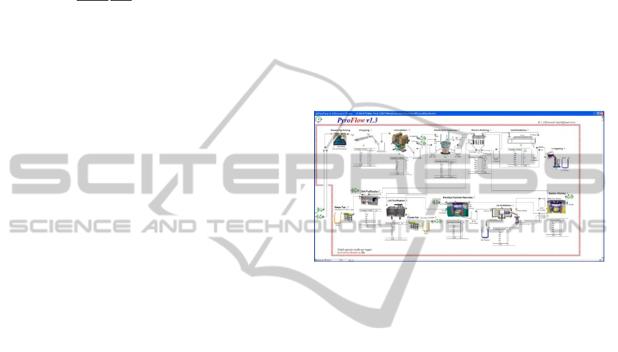
Figure 4: Top window of pyroprocessing plant model.
5 RESULTS AND DISCUSSIONS
5.1 Top Model Design
Figure 4 presents the top model just embrassing
operation model and dynamic mass balance
calculation algorithm. It shows basic information of
material flow by means of visualizaiton through
animation which indicates text and picture
information changes according to time.
Multi-tiered model architecture might be simply
represented on the model by hierarchy. Complex
details corresponding to lower tiers could be hidden
and on top window only a little information might be
displayed. For example, electrolytic reduction
process wants U
3
O
8
powder and recycled or fresh
LiCl salt as feeding material, and pushes output
material into temporary buffers every batch
operation. Basic information that unit process block
includes is input connectors, output connectors,
buffer accumulation, processed quantity, the number
of batch operation and operation status as shown in
Figure 5.
The input and output connectors with names
indicate types of the feeding material and output
product, respectively. The buffer might be real or
Plant Level Framework for Material Flow in a Nuclear Reprocessing Facility
381
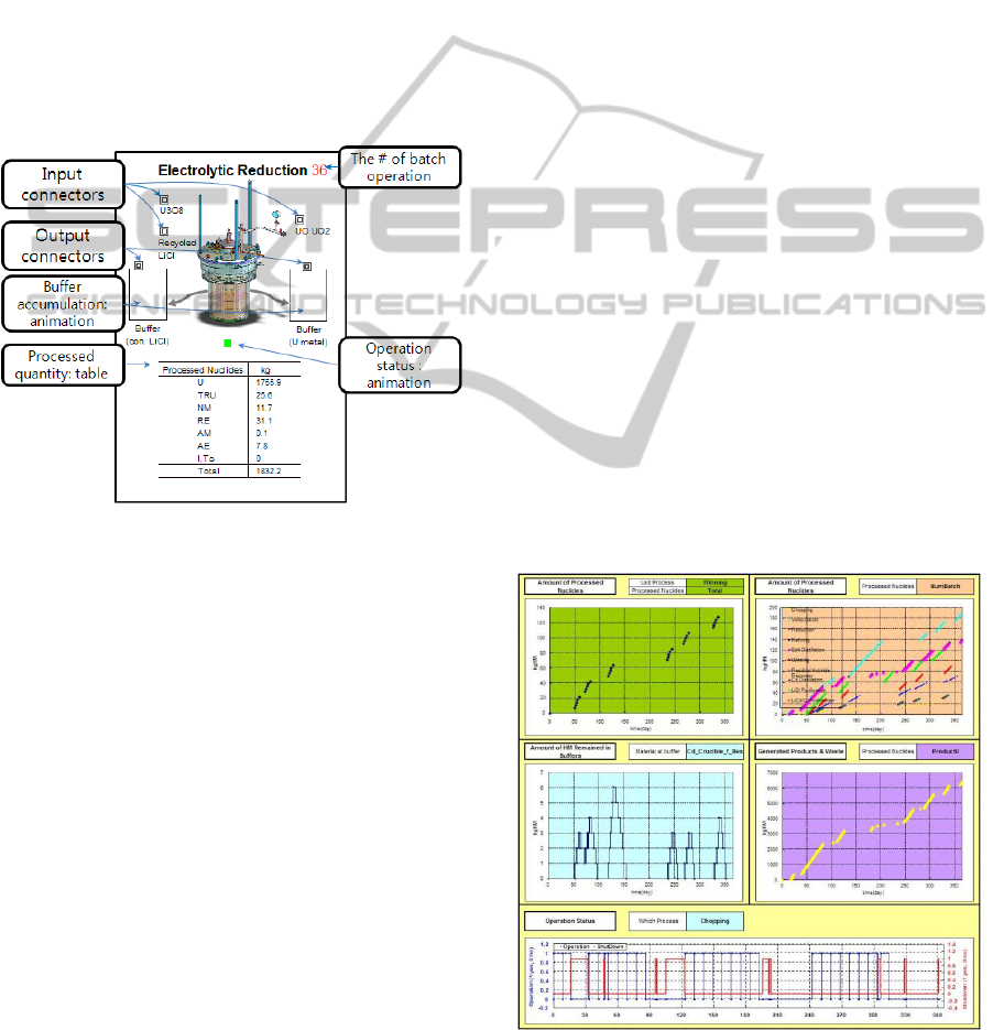
imaginary but most pyroprocessing unit is operated
in batch type so it is important to have sufficient
storage between unit processes to prevent being
stuck. The buffer accumulation is animated with the
level of tank. The table below the picture icon
indicates processed quantity of grouped element
which changes dynamically. On the right side of the
process name, the number of batch operations is
displayed up to now, which is also changed
dynamically according to event. The last information
of unit process block is operation status, which
classified into three kinds: in operation, in
breakdown and out of order. The above information
is much enough to deliver what happens in the unit
process to user during simulation.
Figure 5: Configuration of unit process block on the plant
level top window.
However, detailed numeric results obtained from
simulation might be stored in external database
management software such as EXCEL, ACCESS
and SQL. Specifically, log data describing history
statistics for simulation time should be stored in the
above mentioned DB SWs. Also, numeric results
must be shown in easy ways by using charts and
graphs. The more data are generated, the greater care
should be devoted to visualization in consideration
of what users should look at and how efficiently
results could be shown.
5.2 Function of Current Version
For more realistic simulation, it is assumed that unit
process is possible to be out of order. Besides, many
factors are assumed since real facility has not been
developed. Process time, failure rate, batch capacity,
the number of equipment and the arrival of spent
nuclear fuel are assumed on the basis of
experimental experience or achievable goal based on
the current level of technology, otherwise, set by
design goal.
In the current version of framework, results are
exported to EXCEL and displayed on charts in real
time since it is fast enough to treat limited data.
However, the more data might require more efficient
DB management SW other than EXCEL. Figure 6
shows results able to be displayed in the current
version. The processed mass of grouped element or
total heavy metal of spent fuel is displayed being
classified by unit process. The number of batch
operations tells us which process is late determining
process or bottleneck process during simulation time.
The buffer accumulation indicates that the facility
has a minimum size of buffer storage to temporarily
accommodate product to be sent to the next process.
Also, product and waste mean final output in the
pyroprocess, which will be sent to metal fuel
fabrication facility for recycling and to an interim
storage facility for disposal.
The framework will be more modularized in the
next version to include much more control function
and information and to be simplified in the top
window. Also, material flow will be broken down
from element level into isotope level, which means
over 1,000 isotopes must be tracked according to
time and event. In addition, the plant-level
framework will be enhanced to be linked with other
nuclear related codes for decay heat, isotope
composition, criticality and radioactivity calculation
if necessary. Regarding DB, restructuring might be
needed in order to manage more data at high speed.
Figure 6: Analysis results able to be obtained from current
version of plant level model.
SIMULTECH 2012 - 2nd International Conference on Simulation and Modeling Methodologies, Technologies and
Applications
382

6 CONCLUSIONS
Plant-level framework consisting of 3-tiered model
with some functional modules was suggested for
pyroprocessing facility. Current version of
framework includes basic function for material flow
analysis. One of important characteristic in the
current version is that dynamic mass balance
calculation is possible even without unit process
model. It can make us estimate integrated material
flow in the pyroprocessing facility. The plant model
framework will be improved to satisfy facility code
requirement and to provide various analysis linked
with nuclear related codes. Modelling and
simulation for pyroprocessing facility is expected to
save construction cost and reduce design error,
finally devote generation of design requirement for
engineering scale or commercialized scale facility.
ACKNOWLEDGEMENTS
This work was supported by Nuclear Research &
Development Program of National Research
Foundation of Korea (NRF) funded by Ministry of
Education, Science & Technology (MEST).
REFERENCES
DePaoli, David, 2011. Modeling and Simulation of
Nuclear Fuel Recycling Systems, Short Course of
“Introduction to Nuclear Chemistry and fuel cycle
separations.”
ExtendSim, http://www.extendsim.com
Kim, E. H., 2006. Current status on development of P&T
in Korea, In: Proceedings of the 9th Information
Exchange Meeting on Actinide and Fission Product
Partitioning & Transmutation, Nimes, France.
Lee, H. J. et al., 2009. Discrete event system simulation
approach for an operation analysis of a headend
process facility. Nucl. Eng. Technol. 41, 739-746.
Lee, H. J. et al., 2011, Discrete event dynamic system
(DES)-based modeling for dynamic material flow in
the pyroprocess, Annals of nuclear energy, 38, 860-
875.
McCaskey, A., Billings, J., Almeida, V., 2011. The
nuclear energy advanced modelling and simulation
safeguards and separations reprocessing plant toolkit,
ORNL/TM-2011/261.
Okamura, N., Sato, K., 2002, Computer code system for
the R&D of nuclear fuel cycle with fast reactor. IV.
Development of an object-oriented analysis code for
estimation of the material balance in the pyrochemical
reprocessing process, Cycle system technical report, 3,
1-10.
You, G. S. et al., 2007. Status of technology and policy of
nuclear spent fuel treatment in advanced nuclear
program countries and relevant research works in
Korea. Journal of the Korean Radioactive Waste
Society, 5, 339-350.
Plant Level Framework for Material Flow in a Nuclear Reprocessing Facility
383
