
Enhancing the RAMSAS Method for System Reliability Analysis
An Exploitation in the Automotive Domain
Alfredo Garro and Andrea Tundis
Department of Electronics, Computer and System Sciences (DEIS), University of Calabria,
Via P. Bucci 41C, 87036, Rende (CS), Italy
Keywords: Reliability Analysis, Model-based Systems Engineering, SysML, Automotive Industry.
Abstract: The paper proposes an enhancement and exploitation of the RAMSAS method, a model-based method for
system reliability analysis which combines in a unified framework the benefits of popular OMG modeling
languages (UML, SysML) with the wide adopted Mathworks simulation and analysis environments
(Matlab, Simulink). The flexibility and scalability of the proposal, as well as its effectiveness in evaluating
through simulation the system reliability performances, is exemplified through a case study in the
automotive domain.
1 INTRODUCTION
Reliability analysis is an important task in modern
engineering design especially for mission critical
systems where reliability represents an important
non-functional requirement to be satisfied (Dodson,
Nolan, 2001). However, the increase in both system
complexity and accuracy required to the reliability
analysis, makes often the traditional analysis
techniques, which are mainly based on statistical and
probabilistic tools and on the hierarchical
decomposition of the system, inadequate. Moreover,
the integration of these techniques in a typical
system development process, and especially in the
design phases, is quite difficult and thus their use is
often postponed to the later development stages with
the risk of having to revise even basic design choices
and with a consequent impact on both the
completion time and development cost.
In this context, the paper presents an
enhancement and exploitation in the automotive
domain of a recently proposed model-based method
for system reliability analysis (RAMSAS) (Garro et
al., 2011; Garro, Tundis, 2012).
The proposed method is centered on a classical
iterative process which consists of four main phases:
Reliability Requirements Analysis, System Modeling,
System Simulation, and Results Assessment. In
particular, in the first phase, the objectives of the
reliability analysis are specified and the reliability
functions and indicators to evaluate during the
simulation are defined. In the System Modeling
phase, the structure and behavior of the system are
modeled in SysML (OMG Systems Modeling
Language) by using zooming in-out mechanisms;
moreover, specific behaviors, which model the
onset, propagation and management of failures, are
introduced (a wide set of basic failure behavior
patterns have been defined). In the System
Simulation phase, the previously obtained models of
the system are represented in terms of the constructs
offered by the adopted simulation platform
(D’Ambrogio et al., 2011). Finally, simulation
results are analyzed with respect to the objectives of
the reliability analysis along with specific design
suggestions; moreover, if necessary, new partial or
complete process iterations are executed.
The proposed model-based method has been
applied in the automotive domain for the analysis of
an Electronic Stability Control (ESC) System (De
Filippi et al., 2010), and, in particular, for the
reliability analysis of the Anti-lock Brake System
(ABS) (Goga et al., 2012).
The rest of the paper is structured as follow:
Section 2 summarizes the RAMSAS method;
Section 3 shows the application of RAMSAS in the
automotive domain; finally, conclusions are drawn
and future work delineated.
328
Garro A. and Tundis A..
Enhancing the RAMSAS Method for System Reliability Analysis - An Exploitation in the Automotive Domain.
DOI: 10.5220/0004060003280333
In Proceedings of the 2nd International Conference on Simulation and Modeling Methodologies, Technologies and Applications (SIMULTECH-2012),
pages 328-333
ISBN: 978-989-8565-20-4
Copyright
c
2012 SCITEPRESS (Science and Technology Publications, Lda.)
2 RAMSAS: A MODEL-BASED
METHOD FOR SYSTEM
RELIABILITY ANALYSIS
The RAMSAS method aims to support the analysis
and improvement of the reliability properties of a
system during a System Engineering (SE) process
both in the early design phases and verification
phases. In the former phases, RAMSAS supports the
evaluation and validation of configuration scenarios
and settings of system parameters so to guide and
suggest design choices; in the verification phases
RAMSAS allows verifying through simulation the
reliability performance of the system.
RAMSAS is a method for non-functional
requirements analysis which adopts a model-based
approach for system reliability analysis. It is
centered on a popular UML-based language for
system modeling (SysML) and on a de facto
standard platform for the simulation of multi-domain
dynamic and embedded systems (Mathworks
Simulink). An extensive description of the
RAMSAS method can be found in (Garro et al.,
2011; Garro, Tundis, 2012) along with its
exploitation in the avionics domain for the reliability
analysis both of a Landing Gear System (Garro, et
al., 2011) and of a Flight Management System
(Garro, Tundis, 2012). In the following, an overview
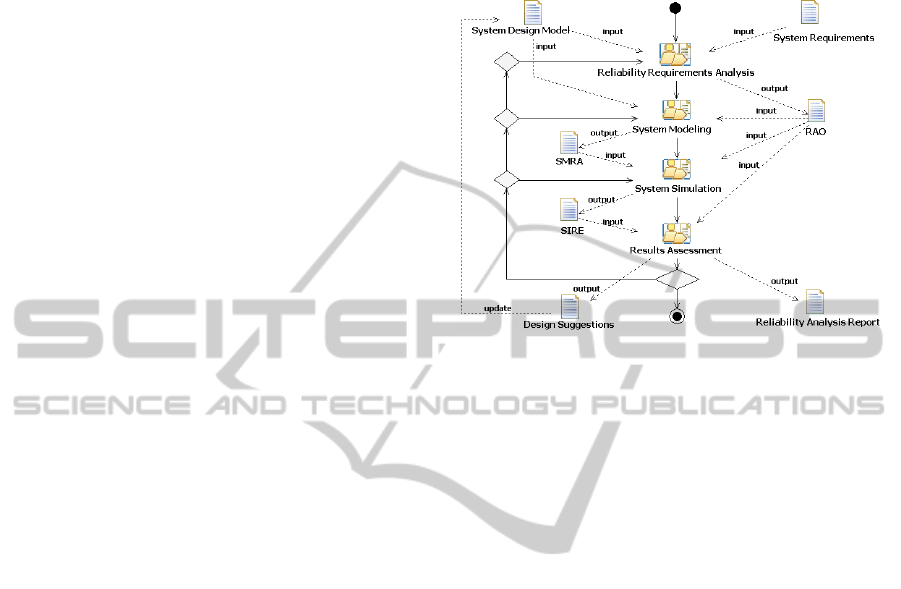
on the process defined by RAMSAS (see Figure 1)
is reported along with the new and last enhancement
of the method.
RAMSAS is centered on four main phases:
Reliability Requirements Analysis, System Modeling,
System Simulation, and Results Assessment.
In the first phase, the objectives of the system
reliability analysis are specified. The inputs of this
phase are the work-products typically resulting from
the previous System Design phases as System
Design Models (SDM) and System Requirements
(SR). Starting from this documentation, the
scenarios to be analyzed, the functions that the
system has to perform, the related operative
conditions, and the reference time horizons should
be clearly individuated and the Reliability Analysis
Objectives (RAO) work-product produced in output.
Moreover, the reliability functions and indicators, to
be derived from the analysis of the simulation
results, must be identified along with the main
analysis techniques to be applied to the data
gathered from simulation.
In the System Modeling phase the structure and
behavior of the identified scenarios are modeled in
SysML. In this phase the system is decomposed in
“component entities” by applying in-out zooming
mechanisms and several decomposition levels
should be considered such as system, subsystems,
equipment, and components; however, different and
deeper hierarchies can be also introduced.
Figure 1: The RAMSAS method (a process view).
Each entity is modeled as a SysML Block whose
structure is defined by both a Block Definition
Diagram (BDD) and an Internal Block Diagram
(IBD) and whose behavior can be defined through a
set of SysML Activity, Sequence, and Statechart
Diagrams. Moreover, special tasks, which model the
onset, generation, evaluation, propagation and
management of block failures, are specified. Finally,
SysML Parametric Diagrams are introduced for
supporting specific analysis by defining constraint
blocks which express mathematical equations and
their parameters that may correspond to block
properties and behaviors. As a result of the System
Modeling phase, the System Models for Reliability
Analysis (SMRA) work-product is produced.
In the System Simulation phase, the previously
obtained models of the system are represented in
terms of the constructs offered by Mathworks
Simulink. The data generated from simulations are
reported in the Simulation Results (SIRE) work-
product.
In the Results Assessment phase, the simulation
data are analyzed with reference to the objectives of
the reliability analysis and the following work-
products are obtained: Reliability Analysis Report
(RAR), Design Suggestions (DS). Several analyses
can be directly performed in Simulink, whereas
more advanced analysis can be performed by
external analysis tools by exporting the obtained
results through the Matlab Workspace.
As for any iterative process, new (partial or
complete) iterations can be executed for achieving
new or missed analysis objectives.
Enhancing the RAMSAS Method for System Reliability Analysis - An Exploitation in the Automotive Domain
329
3 RELIABILITY ANALYSIS OF
AN ELECTRONIC STABILITY
CONTROL SYSTEM
The Electronic Stability Control (ESC) system is one
of the latest vehicle technologies which aims at
reducing crash and fatality rates by helping drivers
to maintain control of their vehicles (De Filippi et
al., 2010). A typical ESC System consists of the
following main subsystems: Electronic Control
Module (ECM), Traction Control System (TCS),
Electronic Brake-force Distribution (EBD) and the
Anti-lock Brake System (ABS).
In particular, the ABS consists of the following
major equipment: (i) wheel speed sensors, mounted
directly on the rotating components of the drive train
or wheel hubs; (ii) an ABS modulator for reducing
and holding the pressure of the wheel brakes; (iii)
Pumps to allow the ABS modulator reducing
pressure on the brake of each wheel and restoring
the pressure when required; (iv) an Electronic
Control Unit (ABS Controller) which manages the
other equipment; (v) an ABS indicator to inform on
abnormal behavior on the ABS operations.
Generally, the ABS uses the wheel speed sensors
and it has the ability to apply brake pressure to a
single wheel and, if required, a sensor that detects
the direction of the vehicle can be also added. The
ABS receives a feedback from the control system
that modulates the brake pressure in response to
wheel deceleration and wheel angular velocity to
prevent the controlled wheel from locking, and it
shuts down when the vehicle speed is below a pre-
set threshold. Different schemes can be used for an
ABS depending on the type of brakes in use and
each schema consists of numerous components, thus
the complete description of them is beyond the
scope of this paper; however, a complete system
configuration has been considered for evaluating its
reliability performance through RAMSAS.
3.1 Reliability Requirements Analysis
The Reliability Requirements Analysis phase takes
as input a description of the system under
consideration in term of both System Requirements
(SR) and System Design Models (SDM). SR includes
functional (FR) and non-functional requirements
(NFR), whereas SDM provides a system
representation in terms of its architecture and
behavior. In particular, among the NFR, the
Reliability Requirements (RR) specify the ability
required for the system in performing the functions
specified in FR under specific stated conditions and
for a specified period of time. In addition, a Failure
Modes and Effects Analysis (FMEA) (Dodson,
Nolan, 2001) can be also provided to highlight the
potential failure modes of the system along with
their severity and likelihood.
Under normal braking conditions the driver
controls the brakes but, during severe braking or on
slippery roadways, when the driver causes the
wheels to approach lockup, the antilock system takes
over. ABS modulates the brake line pressure
independent of the pedal force, to bring the wheel
speed back to the slip level range that is necessary
for optimal braking performance, this implies to (i)
reduce stopping, (ii) improve steer-ability, and (iii)
improve stability.
Starting from the SR, the Reliability Analysis
Objectives (RAO) work-product is produced to
identify both the reliability indicators and the
scenarios of interests, along with the main analysis
techniques to be applied to the data gathered from
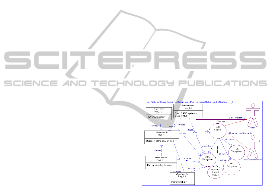
simulation. As an example, Figure 2 shows a visual
representation of the ESC System and its main
subsystems along with the requirements to satisfy
and the main actors which interact with the System.
Figure 2: Top level allocation of the System Requirements
(SR) of the ESC (Electronic Stability Control) System.
3.2 System Modeling
In the System Modeling phase, starting from the
SDM and RAO work-products, the System is
modeled according to the individuated analysis
objectives by executing four modeling activities:
System Structure Modeling, System Behavior
Modeling, System Failure Modeling and System
Integration Modeling.
In the System Structure Modeling activity, the
system structure is modeled using SysML BDD
(Block Definition Diagram) and IBD (Internal Block
Diagram) diagrams and following a top-down
approach. To allow system analysis at the desired
SIMULTECH 2012 - 2nd International Conference on Simulation and Modeling Methodologies, Technologies and
Applications
330
level of details, further abstraction levels can be
introduced by applying a zooming-in mechanism. As
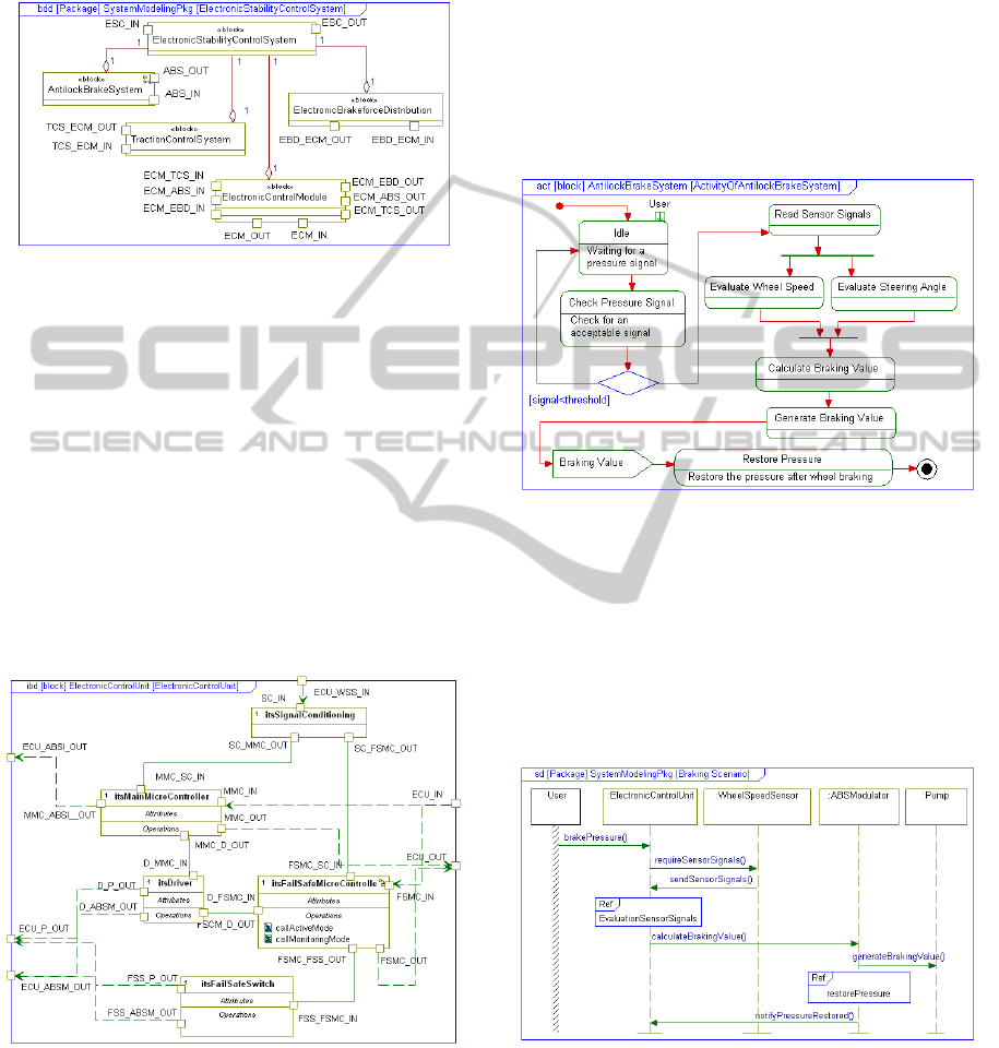
an example, Figure 3 shows the BDD of the ESC
System in which its ports and parts are represented.
Figure 3: BDD of the ESC System.
Figure 4 shows the IBD of the Electronic
Control Unit (ECU) of the ABS sub-system which is
composed by the following components: (i) a
SignalConditioning, which converts the signals,
coming from the sensors to make them available to
the MainMicroController; (ii) a
MainMicroController, which elaborates the
information received from the SignalConditioning;
(iii) a FailSafeMicroController, to monitor the
MainMicroController and replace it in case of fault
(iv) a FailSafeSwitch to disconnect the actuators; (v)
a Driver, which receives commands from the
MainMicroController and pilots the ABSModulator
and a Pump for each wheel.
Figure 4: IBD of the Electronic Control Unit.
In the System Behavior Modeling activity the
behavior of the system is specified following the
same layered approach but combining the top-down
with a bottom-up strategy by exploiting Activity,
Sequence and Statechart Diagrams. In particular, for
each block several tasks can be defined each of
which is related to a specific function provided by
the block and modeled through an Activity Diagram.
In Figure 5, a specific task of the ABS sub-system is
modeled as a flow of the following actions: (i)
Check Pressure Signal, that controls the pressure
level provided by the car user; (ii) Evaluate Wheel
Speed and Evaluate Steering Angle, which evaluate
vehicle wheel speed and steering angle; (iii)
Calculate Braking Value and Generate Braking
Value, which calculate and generate the right
pressure for the wheel in order to control the brake.
Figure 5: Antilock Brake System main task.
From a specific Activity Diagram different paths
of execution (or scenarios) can be individuated and
modeled by Sequence Diagrams so to highlight both
the (sub)blocks involved in the task and interactions
among them in terms of exchanged messages. As an
example, in Figure 6, a scenario of the ABS sub-
system which is triggered by the brakePressure
message is reported.
Figure 6: An interaction oriented view of a specific
execution path.
The behavior of each block can be described by
Statecharts in terms of internal states, operation
mode and triggering events. In Figure 7 the behavior
of the FailSafeMicroController, which is a
component of the ECU unit, is reported. In
Enhancing the RAMSAS Method for System Reliability Analysis - An Exploitation in the Automotive Domain
331
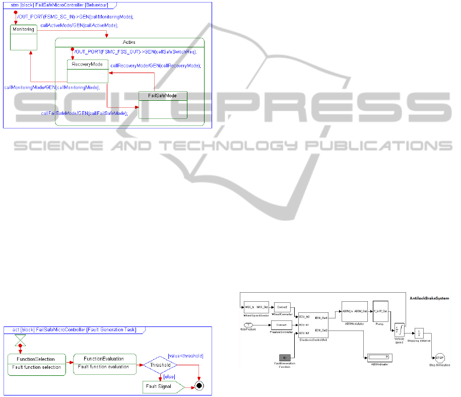
particular, when the entire system is turned on, the
component goes in the Monitoring state by checking
the MainMicroController component that
accomplishes the ElectronicControlUnit tasks. If
system faults occur the FailSafeMicroController is
ready to replace the MainMicroController by
changing its state in Active, and, in particular, going
in the RecoveryMode state or in the FailSafeMode
depending on the result of the recovery actions.
Figure 7: The behaviour of the FailSafeMicroController
component.
In the System Failure Modeling activity, for each
block to check, a set of specific tasks, called
FaultGenerationTasks, are introduced to induce
abnormal block behaviors and analyze their impact
both on the block and the enclosing system.
A model of a FaultGenerationTask for the
FailSafeMicroController is shown in Figure 8
through an Activity Diagram. The task models a
fault generation process that it is activated with a
given time period; upon activation, a desired fault
generation function is selected, then this function is
evaluated and, finally a possibly component fault is
generated and a FaultSignal sent.
Figure 8: A FaultGenerationTask for the
FailSafeMicroController component.
In the System Integration Modeling activity,
normal and abnormal behaviors are integrated to
obtain an overall model of the entire system. It is
worth noting that FaultGenerationTasks are very
important during the simulation to generate and
evaluate abnormal behaviors of the system and
analyze the possible consequent of failures as well
as the feasible actions for their management in order
to improve system reliability.
3.3 System Simulation and Results
Assessment
The objective of the System Simulation phase is to
evaluate through simulation the reliability
performance of the system and, possibly, compare
different design alternatives and parameters settings.
In this phase the System Models for Reliability
Analysis (SMRA) obtained in the previous phase are
represented in terms of the constructs provided by
the chosen simulation platform by executing the
following three activities: Modeling Transformation,
Parameters Setting, and Simulation Execution.
In the Modeling Transformation activity the
SMRA are transformed in an Executable System
Model (ESM). In particular, in the current version of
the RAMSAS method the ESM is generated for the
Mathworks Simulink platform. As shown in Figure
9, the FaultGenerationTask of Figure 8 has been
injected in the Simulation Model as a Simulink
FaultGeneration function, whose parameters can be
suitably tuned according both on the characteristics
of the fault and the scenario to simulate. In the
Parameters Setting activity, the ESM is refined so to
allow the setting of system and configuration
parameters that determine different simulation
scenarios and influence system reliability
performances. Finally, in the Simulation Execution
activity, the data generated from the simulations are
reported in the SIRE work-product in order to make
them available for the Results Assessment phase.
Figure 9: A screenshot of a Simulink-based Executable
System Model.
In the Results Assessment phase the data of the
SIRE work-product are elaborated so to obtain
important information on the reliability properties of
the system under consideration. In the conducted
case study different simulations have been executed
for analyzing the behavior of the System in different
scenarios and evaluating its reliability functions and
indicators as stopping distance, steer-ability and
stability.
During the experimentation several abnormalities
SIMULTECH 2012 - 2nd International Conference on Simulation and Modeling Methodologies, Technologies and
Applications
332

were found. As an example, a frequent failure of the
MainMicroController component, caused by the
raising of temperature over +135 °C, is emerged
with a subsequent swapping of the control to the
FailSafeMicroController component, and the
frequent disabling of the actuators with the
consequent shutdown of the ABS subsystem. To
overcome this abnormal behavior, which is emerged
in the simulation phase and reported in the DS
(Design Suggestions) document, a cooling fan and
the related task for its management have been
introduced. This task is able to turn cooling fan on
when temperature is higher than a fixed threshold by
avoiding an unnecessary operation of switching and
improving, as a consequence, the performance of the
overall ESC system and its reliability.
4 CONCLUSIONS
Despite a general consensus on the advantages that
could derive from the exploitation of model-based
approaches for system reliability analysis, the use of
these techniques has been traditionally unusual and
has not been recommended by international
standards until recently (IEC 61508, 2010). This
delay in the adoption is mainly due to the lack of
methods able to integrate available modeling
languages, tools and techniques in a consistent
modeling framework. To contribute to fill this lack,
the paper has presented an enhancement of a model-
based method for System Reliability Analysis
(RAMSAS), recently proposed in (Garro et al.,
2011; Garro, Tundis, 2012), through a case study in
the automotive domain concerning the reliability
analysis of an Electronic Stability Control system. In
particular, in the exploited version of RAMSAS the
following improvements have been introduced: (i)
the System Modeling phase now consists of four new
modeling activities (System Structure Modeling,
System Behavior Modeling, System Failure
Modeling, and System Integration Modeling); (ii) a
complementary adoption of Activity, Sequence, and
Statechart Diagrams for the behavioral modeling of
the system is proposed; (iii) the System Simulation
phase now consists of three new simulation activities
(Modeling Transformation, Parameters Setting, and
Simulation Execution); (iv) the Design Suggestions
(DS) document, produced in the Results Assessment
phase, adopts typical FMECA and FTA formats so to
ease the use of RAMSAS in conjunction with
classical RAMS techniques.
The proposal is strongly related to the approach
presented in (Cressent et al., 2011), however, as it
strongly relies on the Method Engineering paradigm
(Henderson-Sellers, 2003) its main ambition is to
provide a self-consistent method fragment for
system reliability analysis which can be easy
pluggable in various phases of a typical system
development process.
ACKNOWLEDGEMENTS
Andrea Tundis was supported by a grant funded in
the framework of the “POR Calabria FSE
2007/2013”.
REFERENCES
Cressent, R., Idasiak, V., Kratz, F., David, P., 2011.
Mastering safety and reliability in a model based
process. In Proc. of the Reliability and Maintainability
Symposium (RAMS). Lake Buena Vista, FL, USA,
January 24-27.
De Filippi, P., Tanelli, M., Corno, M., Savaresi, S. M.,
2010. Toward electronic stability control for two-
wheeled vehicles. In Proc. of the ASME Dynamic
Systems and Control Conference (DSCC). Boston,
MA, USA, September 13-15.
Dodson, B., Nolan, D., 2001. Practical Reliability
Engineering. John Wiley & Sons Ltd.
D’Ambrogio, A., Iazeolla, G., Pieroni, A., Gianni, D.,
2011. A model transformation approach for the
development of HLA-based distributed simulation
systems. In Proc. of the Int. Conf. on Simulation and
Modeling Methodologies, Technologies and
Application (SIMULTECH). Noordwikerhout, The
Netherlands, July 29–31.
Garro, A., Tundis, A., Chirillo, N., 2011. System
reliability analysis: a model-based approach and a case
study in the avionics industry. In Proc. of the 3rd Air
and Space Int. Conf (CEAS). Venice, Italy, Oct 24-28.
Garro, A., Tundis, A., 2012. A model-based method for
system reliability analysis. In Proc. of the Symposium
on Theory of Modeling and Simulation (TMS’12).
Orlando, FL (USA) 26-29 March.
Goga, V., Jediný, T., Královič, V., Klúčik, M., 2012.
Mechatronic model of Anti-lock Braking System (ABS)
- A Book Chapter of Mechatronics. Springer.
Henderson-Sellers B., 2003. Method engineering for OO
systems development. Communications of the ACM,
Vol. 46, No. 10, pp.73–78.
IEC 61508, 2010. Functional safety of
electrical/electronic/programmable electronic safety-
related systems, Parts 1-7.
Enhancing the RAMSAS Method for System Reliability Analysis - An Exploitation in the Automotive Domain
333
