
Autonomous Constructing Everyday Projected Displays
Cui Xie, Qi Wang and Wei Cheng
Department of Computer Science, Ocean University of China, 238 Songling Road, Qingdao, China
Keywords: Projector-based Display, Image Warping, Automatic Geometric Correction, Non-Planar Surface.
Abstract: This paper presents an autonomous geometric correction method to support constructing a projector-based
large display for everyday use, which includes offline and online processing phase. The offline process is
focus on an automatic, fast and robust approach for the geometric registration of projector-camera system.
The online stage is mainly the implementing real-time image warping via modern graphics hardware to
achieve the final corrected images without first acquiring geometric information of the screen’s surface.
Since a simple checkerboard pattern is used to facilitate building the mapping of the corner correspondences
of projector-camera image, and a perspective projection invariant rational Bezier patch is used to
approximately represent the mapping, our method saves a lot of computing time and become easier and
robust. Therefore, the achieved transformation can be used for online image warping for actual projection.
As a result, a layman user can get a corrected image displayed on a non-planar surface for the point of view
of the camera easily.
1 INTRODUCTION
Portable projectors have become increasingly
cheaper, brighter, and smaller. So, projectors have
been widely used as a display tool for many
applications, such as offices, classes, research
institutes and for home entertainment (Jiang, 2007).
Moreover, multi-projector based displays can
provide seamless display with greater view angle,
higher resolution and immersive experience than
other traditional display technologies. So, many
researches are focus on how to create
projector-based large displays automatically and
quickly.
In most projection-based displays, users have to
deal with the geometric distortion of the projected
image when the projector is located far from the
observer and/or when the 3D screen surface is badly
oriented. By camera-based computer vision
techniques, one solution is to do complex geometric
registration including camera/projector calibration
and 3D screen surface recovering to wrap the
projected image for any viewpoint (Sajadi, 2010).
These classes of automatic methods can be achieved
in different ways. Homography based method is
feasible for constructing large display over flat
surfaces (Chen, 2002); (Raij, 2004); (Jiang, 2007);
(Brown, 2002); (Damera-Venkata, 2007). Structured
light patterns are often used for nonplanar
display,which uses a large number of pre-designed
patterns of light to encode the correspondence pixel
position of the camera and the projector, and then
achieve the geometric registration (Tardif, 2003);
(Raskar, 1999); (Aliaga, 2008). However this
method is complex and time-consuming. Raskar et
al. in (Raskar, 2004) use a stereo camera pair to
reconstruct quadric surfaces and propose conformal
mapping and quadric transfer to minimize pixel
stretching of the projected images. The non- linear
optimization of estimation of the parameters of
quadric transfer is too time-consuming. Recent work
of Sajadi et al. (Sajadi, 2011) have shown that it is
possible to register multiple projectors on non-planar
surfaces using a single uncalibrated camera instead
of a calibrated stereo pair when dealing with
vertically extruded surfaces. Both above methods
make its wide application limited to a series of
special non-planar planes.
An easier way is directly to do geometric
registration by establishing correct projector-camera
matches relative to the observer (Tardif,
2003).Unfortunately, due to the non-linear color
distortion of the camera, noise and the complex
illumination conditions, pure color-based matching
strategies between the images of projector and
camera are usually fail. Sun et al. (Sun, 2008)
proposed a robust checkerboard pattern recognition
180
Xie C., Wang Q. and Cheng W..
Autonomous Constructing Everyday Projected Displays.
DOI: 10.5220/0004070701800185
In Proceedings of the International Conference on Signal Processing and Multimedia Applications and Wireless Information Networks and Systems
(SIGMAP-2012), pages 180-185
ISBN: 978-989-8565-25-9
Copyright
c
2012 SCITEPRESS (Science and Technology Publications, Lda.)
method to help non-planar surface geometry
registration. Sun’s method considers both the
geometric and the color feature of the checkerboard
internal corner, and showed more robustness and
effectiveness than existing corner detection method,
such as Harris, SUSAN, and FAST.
In this paper, we propose an easy way to
automatically build a correct projected display for
everyday users. Our method is motivated by Sun
(Sun, 2008),which use a robust checkerboard pattern
recognition method to build the projector-camera
matches. But different from Sun’s method that using
many planar quad patches to approximate the
nonplanar surface and use homograpy to represent
the mapping between camera and projector
correspondences, our method use rational Bezier
patches to approximately represent the mapping
from camera and projector, which considers the
nonlinearities of projector or camera and achieve
faster and more robust matching.
2 OVERVIEW OF OUR SYSTEM
The proposed system includes one or more
commodity projector for receiving images from the
computer. A common camera is employed to capture
the projected image of projectors and stand for the
position of the viewer. Our method is based on the
following four steps, which can be further divided
into offline and online processing stages. The offline
stage includes the first three steps and the last one is
the real-time stage. More details will be described in
sec. 3.
1). Start projecting and capturing the checkerboard
pattern and detect checkerboard internal crossing
corners.
2). Find camera-projector matchers and build the
transformation R based on the corners
correspondences.
3). Build the similarity transformation S by corners
correspondences and define the spatial
transformation W=R*S for image warp.
4). Using the transformation W=R* S to correct the
geometry of the input image and get the corrected
image for the viewer.
3 DETAIL OF OUR METHOD
3.1 Checkerboard Corner Detection
Considering the distortion of the curved surface,
the quality of the camera and the complex
illumination condition etc., we choose to use the
checkerboard corner detection method of Sun’s
(Sun, 2008) with some implementation changed
and improved. For each pixel P, check it’s
neighbours’ surrounding layer’s points within a
rectangular window(see figure 1). If most of the
surrounding layers with four black and white
intensity shifts, the detected point is a candidate
corner. Then, we refine the corner position with a
cluster method to merge all the detected candidate
corners that are close to each other.
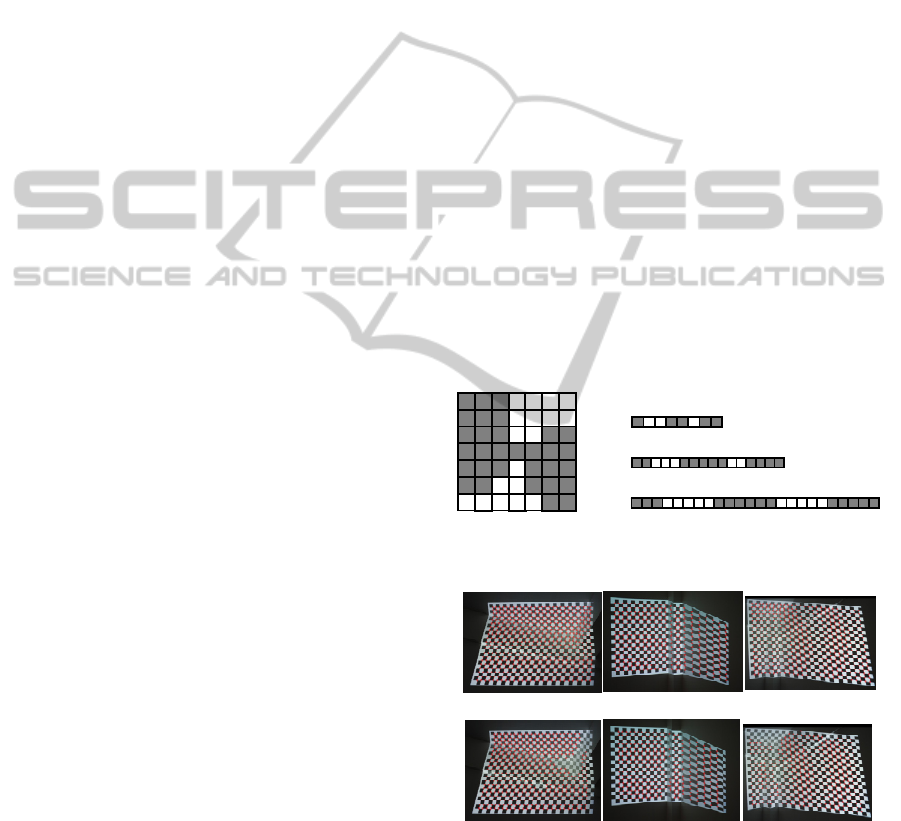
Figure2 (a,b c)
illustrates the detected corners (record as corners
collection N) after clustering with our method.
In order to show the robustness of the corner
detection method, a computer generated source
checkerboard pattern(see figure 3a) is projected on
an arbitrary surface and is captured by a general
low-cost cameras for corner detection test. Do the
above coner detection processing and Opencv’s
(FindChessboardCorner function) (Noah, 2009)
respectively. It is easy to note that our corner
detection result (figure 2(a,b,c)) is better than
Opencv’s result (figure 2(d,e,f)) even with bad
illumination condition and distinct nonplanar surface
deformation.
3 3 3 3 3 3
3 2 2 2 2 2
3 2 1 1 1 2
3 2 1 P 1 2
3 2 1 1 1 2
3 2 2 2 2 2
3
3
3
3
3
3
3 3 3 3 3 3 3
La
y
er1
(
P
)
La
y
er2
(
P
)
La
y
er3
(
P
)
Figure 1: Corner P’s surrounding layers and their four
black and white intensity shifts.
(a) (b) (c)
(d) (e) (f)
Figure 2: Our corners identified result(a,b,c) comparison
with OpenCV’s (d,e,f).
3.2 Corners Matching
In order to recognize the captured checkerboard
pattern, we need to connect the corners into quad
AutonomousConstructingEverydayProjectedDisplays
181
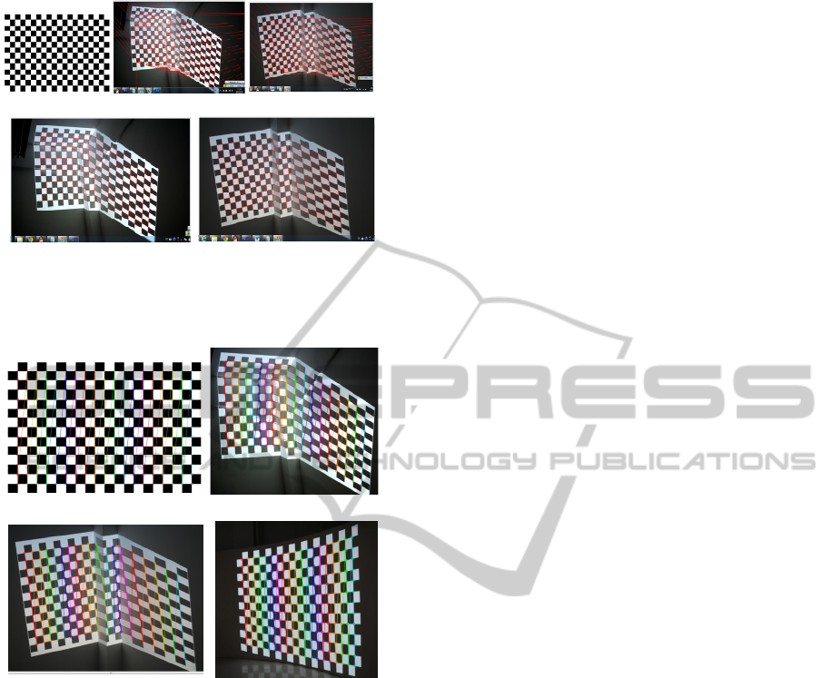
(a) (b) (c)
(d) (e)
Figure 3: A source checkerboard pattern generated by a
computer(a), delaunay triangulation result (b,c) and
regular quad meshes(d,e).
(a) (b)
(c) (d)
Figure 4: The recognized corners are connected with lines
in column order in source checkerboard pattern(a) and
projected checkerboard pictures (b,c and d).
meshes and build the corners matching between the
computer generated checkerboard pattern and the
projected checkerboard pictures captured by a
camera. Here we only consider the grids inside the
checkerboard(see figure4a). First, use the delaunary
triangulation method described in the OpenCV
library to connect all the detected corners (see red
lines in figure 3(b,c)). Then we do edge filtering to
remove the redundant or illegal edges and get a
regular quad meshes.
There are two classes of false edges: first is the
edges crossing the background or go through more
than one quad, and the second class is the diagonal
of each quad. For the first class of false edges, we
use a distance threshold to determine a false edge
and remove it. As for the second class of false edges,
we check for the average color around the detected
edges. If the color on both sides of the edge is
similar, it is the redundant edge and should be
removed. Otherwise keep it. Figure 3(d,e) shows the
quad meshes after false edges filtering and a graph
G(N1,E) with a regular grid topology is achieved.
The next step is to map nodes of the grid to the
corners of the pattern.
To do corner matching, from the upper left the
first corner, according to the column coordinates
order, using topological information, the coordinates
labelling can be done easily. Figure 4 gives the
experiment results of the ordered and connected
corners of source checkerboard pattern and projected
checkerboard respectively. Each color represents a
column of corners and the last corner of one column
is connected to the first corner of next column. From
the result , we can see that the algorithm can
correctly recognize the checkerboard corners on
deformable non-planar surfaces and thus the corners
correspondence is built.
3.3 Constructing Correspondences
Mapping R and R-1
Based on the corner correspondences obtained form
section 3.2, Our method fit a rational Bezier patch
using a non-linear least squares fitting technique to
build the mapping R between these correspondences
from camera image to projector image. The
following experiment results illustrate the
effectiveness of our method. R
-1
means the mapping
from projector image to camera image. To be more
efficient, mappings between each corresponding
point pair can be pre-computed and stored as a pixel
mapping look-up table for online efficient geometric
correction will be more convenient.
3.4 Determining Valid Target Display
Area and Similarity
Transformation S
In order to show the image on a non-planar surface
in an undistorted view with respect to the viewer, a
new proper display area(as is shown in figure 5b)
used for projection of the corrected image, with the
largest possible size, should be defined on the inside
of the captured uncorrected image. Actually, we use
a simple and approximative method to find a
maximum rectangular area within the covered area
of the projector into the camera image. This
rectangle has the same ratio as the initial source
image and has the same center of gravity as the
coverage polygon of the camera image. Then the
expected rectangle can be horizontally and vertically
SIGMAP2012-InternationalConferenceonSignalProcessingandMultimediaApplications
182
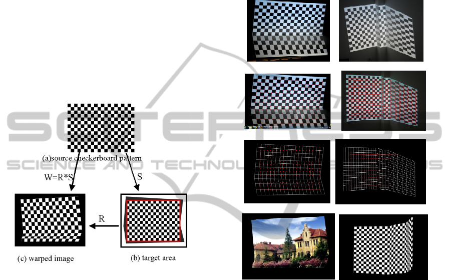
extended starting from the center of the coverage
polygon until one of the corners of the rectangle
reaches the boundary of the coverage polygon. The
red color box of figure 5b shows the valid area used
for actual projection.
Once the target display area is determined, the
correspondences of the corners to the source image
are obtained from a similarity transformation S,
which defines how the source image to be
geometrically corrected in the target area of the
camera image. The similarity transformation S
includes a translation and a scale transformation
between the target display area and the input image.
Figure 6 shows that the original detected corners are
transformed by S into the target rectangle as red
points.
Figure 5: The valid target rectangle area and corners are
transformed into the target rectangle by S.
3.5 Defining Spatial Transformation
The spatial transformation from the source image
(figure 5a) to the target output image(figure 5b)
must be pre-defined to execute
a pre-compensating
inverse distortion(figure 5c) for geometry
correction.
(1) First, do similarity transformation S between the
target rectangle and the source input image to scale
and translate the detected corners into the valid
image area (see figure 5b and figure 6 (b,d)).
(2) Then, apply the transformation R to the corners
of the first processing result and get the warped
transformation W=R*S (figure 5), which maps the
each source corner to the specific target point (see
figure 6 e and f). To be more efficient, mappings
between each corresponding point pair can be stored
as a pixel mapping look-up table for online efficient
geometry correction.
3.6 Online Geometric Correction
Based on hardware-accelerated computer graphics
and combined with an OpenGL texture mapping
technology (see figure 7), the final corrected image
warped by W=R*S can be rendered in real-time and
projected on the screen with visual correct effect.
(a) (b)
(c) (d)
(e) (f)
(g) (h)
Figure 6: (a and b) are camera image, (c) is corners
detection result and (d) is quad meshes. (e, f) show the
valid target rectangle area and corners are transformed into
the target rectangle by S. (g and h) are warped image with
texture mapping by transformation R*S.
4 EXPERIMENT
4.1 Geometric Correction with Single
Projector
To test our method, we first use one projector and
one camera to build a simple projector-camera
system. To simplify the experiment, we set the
viewer and the calibration camera to be the same
position and we can ignore the transformation
between camera and viewer.
Firstly, a checkerboard pattern with resolution
1024 * 768 is generated by our computer. Then it is
projected with same resolution on a cylinder screen
AutonomousConstructingEverydayProjectedDisplays
183
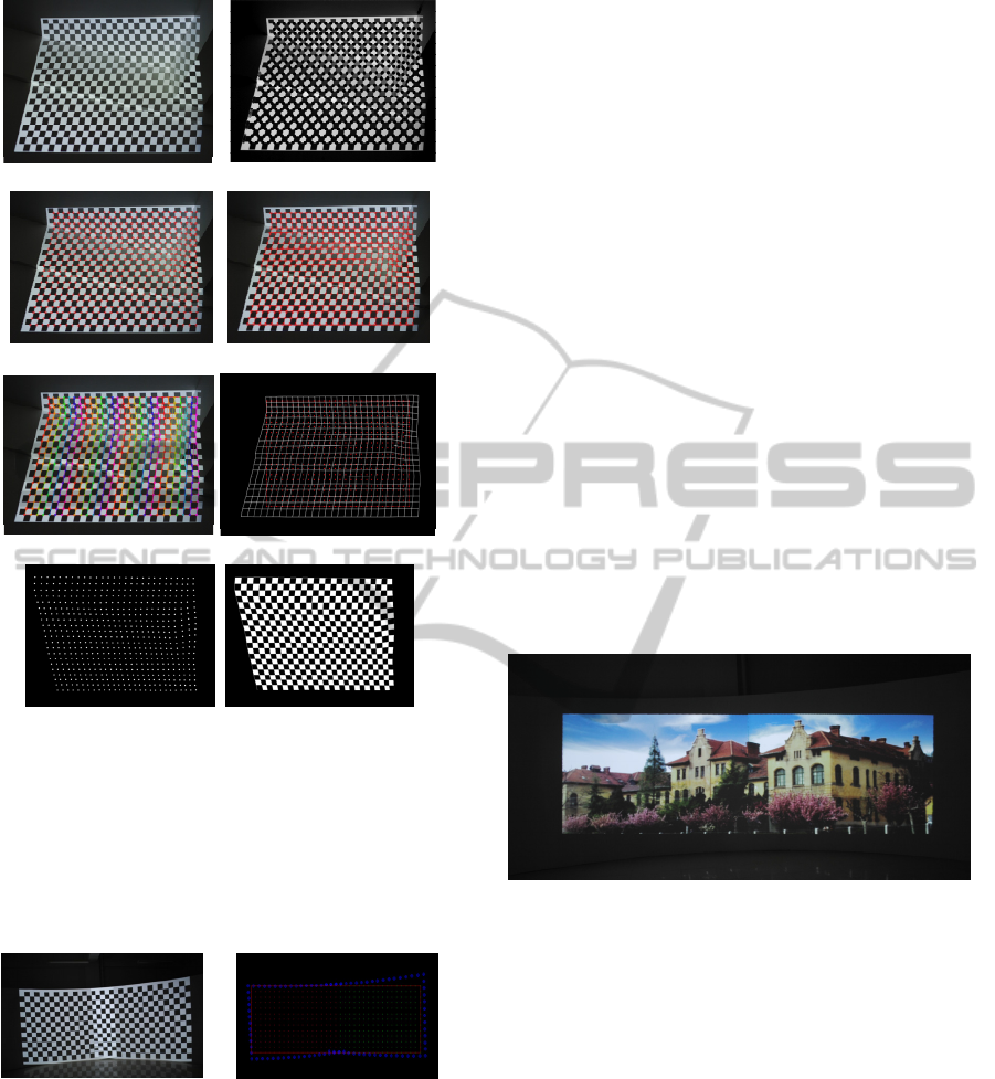
(a) camera image (b) 14.2829s
(c) 4.86319s (d) 0.119737s
(e) 0.00112791s (f) 0.063615s
(g) 0.776364 s (h) warped image
Figure 7: The computing time spend on each processing
step of our method from (a)the camera captured image to
(h)the warped image: (b)corner detection result, (c)
corners clustering, (d)quad meshes,(e)corners ordering and
checkerboard recognization, (f) valid display rectangle and
similarity transformation, (g) spatial transformation of
corners for geometry correction, and (h) warped image
result.
Figure 8: Two projectors
overlapping.
Figure 9: The valid
rectangle covered area.
and is captured by a camera. Here all the images in
our experiment are pre-processed into size of 1024 *
768 resolution. In figure 7, the computing time used
for each processing step is shown.
Using a computer with an Intel Core 2 Duo 2.13
GHz CPU and a 2GB RAM, our implementation
achieved a recognition speed of 15.52s for a 19*13
checkerboard pattern and 19.26s for a 28*21
checkerboard pattern.
4.2 Geometric Correction with
Multi-projectors
In Figure 8, two projectors are used for
multi-projector setup with necessary projection area
overlapping. Notice that the common region is must
but resulting in unwanted intensity fluctuations. We
can use the intensity blending technique to remove
the bright and provide a seamless correct display. To
ensure good result, each projector should cover an
enough large part of the camera image.
The multi-projector display uses the same
geometric principles as the single projector
projection. As long as the covered area projected by
the projectors is visible to the camera and each
projector need to decide it’s own valid projection
area first (see figure 9). Then, compute the
individual mapping R for each separable area of the
projection by corresponding feature points from the
uncorrected and input images. The similarity
transformation S is obtained and the transformation
R*S is applied to each projector and corrected
images are achieved finally (see figure10).
Figura 10: The final corrected image projection.
5 CONCLUSION AND FUTURE
WORKS
The paper presented a simple auto-geometric
correction method for constructing low-cost smart
projector system, which allows projection on
non-planar surface with an uncalibrated camera by a
layman user. The proposed method solves two cases:
single projector and multiple projectors. The rational
Bezier patch is applied to estimate the mapping
relationship with simple computation. The
experimental results of geometry corrected
projection show that the method is automatic, fast
and accurate. In the future, we will focus on the
universality of the correction algorithm. The
SIGMAP2012-InternationalConferenceonSignalProcessingandMultimediaApplications
184

corner-detection time could be decreased using
improved algorithm.
REFERENCES
Jiang Z., Luo X., Mao Y, et al. ,2007. Interactive browsing
of large images on multi-projector display wall
system[C]. Proc. The 12th International Conference
on Human-Computer Interaction. LNCS, vol.
4551,pp. 827-836.
Brown M. S. and Seales W. B., 2002. A Practical and
Flexible Tiled Display System. In Proc of IEEE
Pacific Graphics, pp. 194–203.
Damera-Venkata N., Chang N. L., and DiCarlo Jeffrey M.,
2007.A Unified Paradigm for Scalable Multi-Projector
Displays[J]. IEEE Transactions on Visualization and
Computer Graphics, 13(6), pp.1360-1367.
Tardif J.-P., Roy S., and Trudeau M., 2003.
Multi-projectors for arbitrary surfaces without explicit
calibration nor reconstruction. In Proceeding of
Fourth International Conference on 3-D Digital
Imaging and Modeling, pp.217-224.
Raskar R., Brown M. S., Yang R., Chen W.-C., Welch G.,
Towles H., Seales B., and Fuchs H., 1999.
Multi-projector displays using camera-based
registration. In Proceedings of the 10th IEEE
Visualization 1999 Conference (VIS ’99). Washington,
DC, USA.
Raskar R., J. Baar V., Willwacher T., and Rao S., 2004.
Quadric transfer function for immersive curved screen
displays. Eurographics.
Aliaga D. and Xu Y., 2008. Photogeometric structured
light: A selfcalibrating and multi-viewpoint
framework for accurate 3d modelling. Proc. of IEEE
CVPR.
Sajadi B. and Majumder A., 2010. Auto-calibration of
cylindrical multi-projector systems. In Virtual Reality
Conference (VR), 2010 IEEE, pp. 155 –162 .
Sun W., Yang X., Xiao S., and Hu W., 2008. Robust
checkerboard recognition for efficient nonplanar
geometry registration in Projector-Camera systems. In
Proceedings of the 5th ACM/IEEE International
Workshop on Projector Camera Systems (PROCAMS
'08).
Chen H., Sukthankar R., and Wallace G., 2002. Scalable
Alignment of Large-Format Multi-Projector Displays
Using Camera Homography Trees. In Proceeding of
IEEE Visualization 2002, pages 339–346.
Raij A. and Polleyfeys M., 2004. Auto-calibration of
multi-projector display walls. Proc. of ICPR.
Sajadi B., Majumder A., 2011. Autocalibrating Tiled
Projectors on Piecewise Smooth Vertically Extruded
Surfaces. IEEE Transactions on Visualization and
Computer Graphics, Vol. 17, NO. 9, pp.1209-1221.
Noah K., 2009. OpenCV Tutorial 10 - Chapter 11.
http://dasl.mem.drexel.edu/~noahKuntz/openCVTut10
.html.
AutonomousConstructingEverydayProjectedDisplays
185
