
Development of Computer Algorithms to Control a Weelchair
through the Movement of the Head by Artificial Vision
Ricardo Fuentes Covarrubias
1
, Andrés Gerardo Fuentes Covarrubias
1
, Cristina Conde Vilda
2
,
Isaac Martin de Diego
2
and Enrique Cabello
2
1
Facultad de Ingeniería Mecánica y Eléctrica, Universidad de Colima, Coquimatlán, Colima, C.P. 28440, Mexico
2
Universidad Rey Juan Carlos (URJC), Escuela Técnica Superior de Ingeniería Informática,
Tulipán s/n, Mostoles, Madrid, C.P. 62490, Spain
Keywords: Biometry, Machine Vision, Automatic Recognition.
Abstract: The Purpose of this project is the control of motion and direction in real time of a wheel chair, using
machine vision algorithms. The main goal of this project is the signal acquisition from the video camera and
collision sensors for post processing in the C# algorithms and later obtaining motor control in the traction
mechanism of the wheelchair. The C# algorithm has several tasks. The first is to obtain the real time image
from web cam and later processing for the identification of the direction of movement of the human face.
The second is to calculate the speed of the movement for generation of the PWM output for motor
movement. This information output using the RS232C driver to a microcontroller card attached to a motor
control box in the wheel chair mechanism. The final task is to obtain the collision sensor status for security
implementation, all in real time. The main reason for development of an implementation of this solution is
the use of open source software tools for a more stable platform in the base system due to the characteristics
of the end use of the system. The end user of the system will be quadriplegic people.
1 INTRODUCTION
This project integrates a solution aimed at
controlling a wheelchair by moving the face, using
artificial vision techniques and voice command. This
article only describes the vision module, and details
its main components.
2 STATE OF THE ART
Tracking and measuring drivers’ eyes published by
David Tock and Ian Craw, describing a system of
support for driving an automobile by means of the
movement of the eyes.
Tracking moving heads--processed by Larry S.
Shapiro, Michael Brady, and Andrew Zisserman.
This work describes the design of computational
algorithms to detect movement of the head using
three-dimensional analysis of images.
Control of visually guided behaviors by Jana
Kosecka, Ruzena Bajcsy, and Max Mintz. This
includes/understands the design of a scheme of
guidance for a robot from adjustments of infrared
sensors that detect the shift of position of objects
that comprise a scene and is analyzed based on the
analysis of the system of coordinates of the real
world.
Active exploration of dynamic and static scenes
written by David W. Murray, Ian D. Reid, Kevin J.
Bradshaw, Phillip F. McLauchlan, Paul M. Sharkey,
and Stuart M. Fairley. This describes a technique to
recover in real time the trajectories of sprites which
move on a plane in a scene. The detection of
movement and its segmentation are made in each
scene in time, having compared the changes of
scenes.
Magic Environment by Luis Figueiredo, Tiago
Nunes, Filipe Caetano. With the developed
application of environment control, the authors
intend to provide the user with a simple and
configurable tool according to his or her needs,
involving low cost hardware that enables the control
of any infrared device or any electric device
connected to a radio frequency receiver. A function
can be associated to each button in order to control
an infrared device, an electric device, or both. The
only thing that an eye gaze user will have to do is
select the communication picture button whose
function he or she intends to activate.
62
Fuentes Covarrubias R., Fuentes Covarrubias A., Conde Vilda C., Martin de Diego I. and Cabello E..
Development of Computer Algorithms to Control a Weelchair through the Movement of the Head by Artificial Vision.
DOI: 10.5220/0004073900620067
In Proceedings of the International Conference on Signal Processing and Multimedia Applications and Wireless Information Networks and Systems
(SIGMAP-2012), pages 62-67
ISBN: 978-989-8565-25-9
Copyright
c
2012 SCITEPRESS (Science and Technology Publications, Lda.)
3 METHODOLOGY USED
3.1 The Analysis and Recognition of
the Face Image
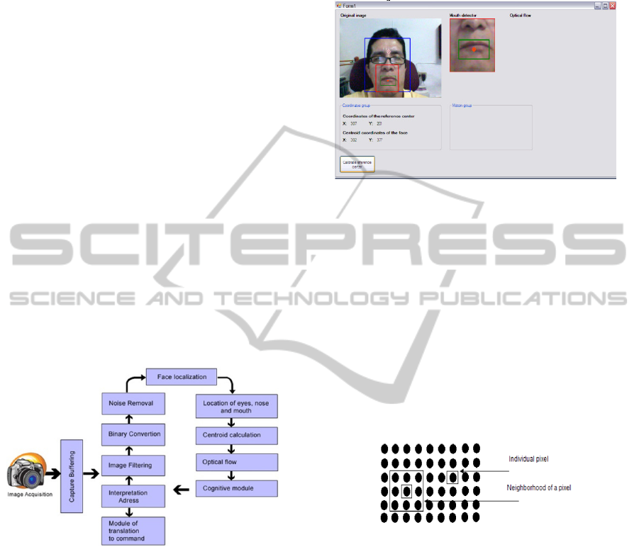
The global structure of the proposed system and
interaction with control software is illustrated in
Figure 1. The scene is analyzed and the face of the
person is located; the person must be at a maximum
distance of 20 cm. from the camera without physical
contact with the device. It is located at a reference
point called the centroid from which references to
the centre between the eyebrows is the calculation of
the distance between the eyes, nose, and mouth. In
this last place the next waypoint marked as detector
is the mouth. Once located, the mouth is the
comparison between the previous and the current
image identifying the movements and changes, as
these are defined as optical flow, which indicate the
direction towards which such movements are made:
left, right, up, or below them that will translate into
motor commands sent to the wheelchair.
We use a webcam as the image acquisition
device and the image quality is shown in figure 2 in
a test pattern routine.
Figure 1: Main scheme of vision system.
The image is captured by a webcam and sent to the
capture buffer. The image is filtered and binarized,
cleans or removes noise, and later sweeps the scene
to locate the face. Once the face is located, it draws a
box to locate within the eyes, nose and mouth with a
calculation to be described in another section to
generate a centroid point which will be between the
eyes. This is important because it allows us to detect
the mouth to the analysis of the last two frames of
the image to identify the sense in which we
generated the displacement of the mouth in the optic
flow module which will send the cognitive module
which is responsible for storing data blocks related
to the optical flow. These send the command
converter module which sends a command to the
power module and this will activate the motor,
thereby achieving wheelchair travel upward to the
left, right or backward. This is shown in Figure 2.
Figure 2: Locating the face image.
3.2 Data Processing
Data processing in the vision system can be played
from two perspectives (Seul et al., 2000):
1. Alterations in pixels of data on a global scale
(individual)
2. Operations based in multiple locations
(neighbourhood)
The generation of the pixels in a new image will be a
function of either the value of each individual pixel
location or the values of the pixels in the vicinity of
a given pixel, as shown in Figure 3.
Figure 3: Functions of point and Neighbourhood.
This figure shows the individuality of a pixel
which shows the representation of this in a picture.
We can also see that the pixel neighbourhood can be
4 or 9 depending on use. Neighbourhood increases
the number of neighbours (Parker, 2011).
3.3 Individual Operations
(Convolution)
Individual operations involve the generation of a
new modified image pixel value in a single location
based on a global rule applied to each location of the
original image. The process involves having the
pixel value at a given location in the image,
modifying it by a linear operation or movement, and
placing the new pixel value in the corresponding
DevelopmentofComputerAlgorithmstoControlaWeelchairthroughtheMovementoftheHeadbyArtificialVision
63

location of the new image. The process is repeated
for each and every one of the locations of the pixels
in the original image.
One of the algorithms used in this project is the
Haar transform, the simplest of the wavelet
transforms. This transform cross-multiplies a
function against the Haar wavelet with various shifts
and stretches, like the Fourier transform cross-
multiplies a function against a sine wave with two
phases and many stretches. (
Bradsky and Kabler,
2008).
The Haar transform is derived from the Haar
matrix. An example of a 4x4 Haar transformation
matrix is shown in the figure 4.
=
1
√
4
1111
1 1 −1 −1
√
2 −
√
2 00
00
√
2 −
√
2
(1)
Figure 4: The Haar transform.
The Haar transform can be thought of as a
sampling process in which rows of the
transformation matrix act as samples of finer and
finer resolution.
Haar matrix
The 2×2 Haar matrix that is associated with the Haar
wavelet is
=
11
1−1
(2)
Using the discrete wavelet transform, one can
transform any sequence
,
,…,
,
of even
length into a sequence of two-component vectors
(
,
),…,(
,
)). If one right-multiplies
each vector with the matrix H2, one gets the result
(
(
,
,…,
,
)
) of one stage of the fast Haar-
wavelet transform. Usually one separates the
sequences s and d and continues with transforming
the sequence s.
If one has a sequence of length in a multiple of
four, one can build blocks of 4 elements and
transform them in a similar manner with the 4×4
Haar matrix
=
1111
1 1 −1 −1
1−10 0
001−1
(3)
which combines two stages of the fast Haar-wavelet
transform.
Compare with a Walsh matrix, which is a non-
localized 1/–1 matrix.
4 OPTICAL FLOW
Optical flow is the pattern of apparent motion of
objects, surfaces, and edges in a visual scene caused
by the relative motion between an observer (an eye
or a camera) and the scene. (Aires et al., 2008);
(John, 1998). The concept of optical flow was first
studied in the 1940s and ultimately published by
American psychologist James J. Gibson (Istance et
al., 2008) as part of his theory of affordance. Optical
flow techniques such as motion detection, object
segmentation, time-to-collision, and focus of
expansion calculations, motion compensated
encoding, and stereo disparity measurement utilize
this motion of the objects surfaces, and edges. (Hans
and Bernd (eds), 1998); (Parker, 2011).
4.1 Lucas Kanade Algorithm
The Lucas-Kanade method (Gary Rost Bradsky,
Adrian Kabler, 2008) assumes that the displacement
of the image contents between two nearby instants
(frames) is small and approximately constant within
a neighbourhood of the point p under consideration.
Thus the optical flow equation can be assumed to
hold for all pixels within a window cantered at p.
namely, the local image flow (velocity) vector (Vx,
Vy) must satisfy
Ix(q1)Vx + Iy(q1)Vy = − It(q1)
(4)
Ix(q2)Vx + Iy(q2)Vy = − It(q2)
.
.
.
Ix(qn)Vx + Iy(qn)Vy = − It(qn)
where q1, q2,..,qn are the pixels inside the window,
and Ix(qi),Iy(qi),It(qi) are the partial derivatives of
the image I with respect to position x, y and time t,
evaluated at the point qi and at the current time.
These equations can be written in matrix form
Av= b, where
=
(
)
(
)
(
)
(
)
⋮⋮
(
)
(
)
,=
,=
−
(
)
−
(
)
⋮
−
(
)
(5)
This system has more equations than unknowns and
thus it is usually over-determined. The Lucas-
Kanade method obtains a compromise solution by
the least squares principle. Namely, it solves the 2×2
system
ATAv = ATb or
v = (ATA) − 1ATb
where AT is the transpose of matrix A. That is, it
computes
SIGMAP2012-InternationalConferenceonSignalProcessingandMultimediaApplications
64
=
(
)
−
(
)
(
)
(
)
(
)
(
)
−
(
)
(
)
−
(
)
(
)
(6)
with the sums running from i=1 to n.
The matrix ATA is often called the structure
tensor of the image at the point p.
4.2 Canny Algorithm
This method was further refined by J. Canny in 1986
into what is now commonly called the Canny edge
detector (Pajarez and De la Cruz, 2002). One of the
differences between the Canny algorithm and the
simpler, Laplace-based algorithm is that in the
Cannny algorithm, the first derivatives are computed
in x and y and then combined into four directional
derivatives. The points where these directional
derivatives are local maxima are then candidates for
assembling into edges. (Bradsky and Kabler, 2008);
(Jain et al., 1995).
Canny assumed a step edge subject to white
Gaussian noise. The edge detector was assumed to
be a convolution filter f which would smooth the
noise and locate the edge. The problem is to identify
the one filter that optimizes the three edge-detection
criteria (Parker, 2011).
An edge in an image may point in a variety of
directions, so the Canny algorithm uses four filters
to detect horizontal, vertical and diagonal edges in
the blurred image. The edge detection operator
(Roberts, Prewitt, Sobel for example) returns a value
for the first derivative in the horizontal direction
(Gy) and the vertical direction (Gx). From this, the
edge gradient and direction can be determined:
=
+
(7)
=arctan
.
The edge direction angle is rounded to one of four
angles representing vertical, horizontal and the two
diagonals (0, 45, 90 and 135 degrees for example).
5 EXPERIMENTAL RESULTS
5.1 Image Processing
The system source code was developed in C # using
open source tools of OpenCV. The main algorithms
involve:
1) Acquisition of the image using a Webcam
2) Conversion to grayscale
3) Binarization and filtering
4) Face Detection algorithm by HAAR
5) Calculation of centroid to locate points of
interest: eyebrows, nose and mouth
6) Location of mouth
7) Identification of the movements of the face
8) Application of Optical Flow algorithm Lukas
Kanade (David J. Fleet and Yair Weiss, 2006).
9) Data Conversion motor direction commands to
the wheelchair
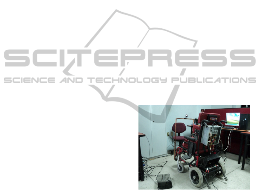
5.2 Stage Control
This project aims to develop computer algorithms to
provide a sliding unit for quadriplegic people as a
guide, by interpreting the movement of the face,
finding the mouth, eyes, and nose using artificial
vision techniques. It also includes the control stage
engine displacement unit which interacts with a
computer and in turn with humans in real time as
shown in Figure 5.
Figure 5: Integrated system.
The system includes a software-hardware
interface which enables or disables the drivers of the
wheelchair, interacting with the cognitive module
which takes decisions to guide the wheelchair to the
place directed by the real-time system.
This system includes the vision module,
software-hardware interface, and the control system.
It includes the manufacture of a joystick for manual
control of the wheelchair and the extended control
that includes control of the wheelchair using
movements locating the head position of the face.
The proposed project includes the modules
shown in Figure 6 below:
DevelopmentofComputerAlgorithmstoControlaWeelchairthroughtheMovementoftheHeadbyArtificialVision
65
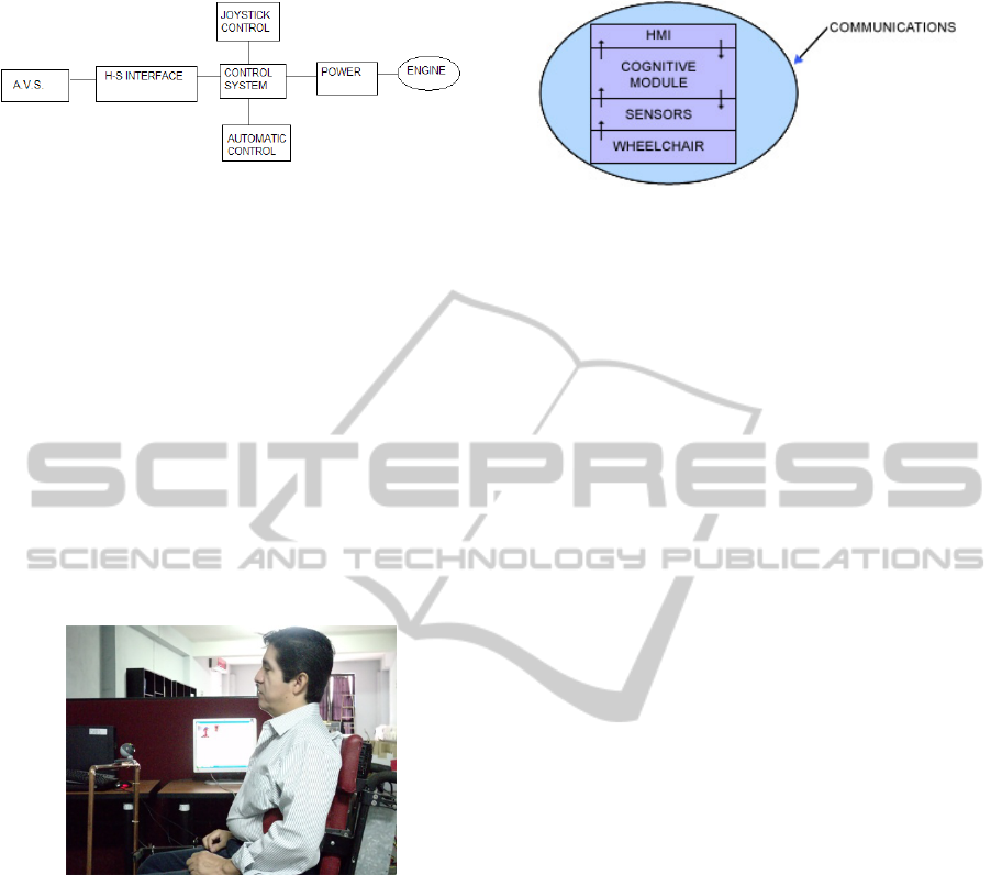
Figure 6: Block diagram of control system.
5.3 Artificial Vision System
This module contains the vision algorithms for real-
time biometric control which will allow indication of
the direction of travel of the wheelchair from the
identification of the position of the face. Generated
algorithms have been mounted in an embedded
system that contains a camera that sends sequences
of frames that are processed in real time. Through its
analysis, it sends a movement command to the
wheelchair control module.
In principle, the system would define the
direction of travel of the vehicle from the analysis of
facial movement by placement of the user's mouth,
as shown in Figure 7.
Figure 7: Integrated system in operation.
6 COGNITIVE MODULE
The scope of the proposal includes a set of sensors
which interact with the machine vision system to
detect environmental conditions that allow the
integrated device to provide a level of security.
Cognitive applications and human interfaces of the
system and the application of cognitive skills are
needed to develop awareness of the environmental
situation monitored. Cognitive capabilities of the
system will allow both the differential capacity
supervised and unsupervised (though always
validated by a human operator), to learn from the
experience. The following figure 8 presents a high-
level architecture of the proposed system.
Figure 8: Architecture of the cognitive module.
The system will integrate an automatic
"cognitive" to ensure a high level of security through
the following capabilities in real time:
- Detection and evaluation of the environment
surrounding the wheelchair
- Intrusion detection (people, animals or moving
objects) in the security area of the wheelchair
- The detection of dangerous situations for the
driver of the wheelchair, such as end of the road,
dangerous edge, and objects prone to collision with
the wheelchair
- Automatic reports of the situation when the right
set of people use predefined procedures based on
risk level assigned previously
The proposal includes the development of a model
for profiling risks that can be used to recognise
abnormal behaviour, as well as the means to identify
the source of the security alert, tracking and back-
tracking capabilities to establish the abnormal
pattern, decision support mechanisms to establish an
action plan, as well as the means to report to the
operator and to distribute the information to the
appropriate security personnel.
7 CONCLUSIONS AND FUTURE
DEVELOPMENTS
In this paper we propose a control application of a
device for driving the movement of a disabled
person using computer vision techniques in real
time. Due to space restrictions we are not including
a description of the other algorithms and hardware
modules used in future studies, or the description of
the algorithms used in the vision system from the
point of view of the system integrated with the rest
of the modules that make up the system, including a
control module for voice command which is in its
early development and testing.
SIGMAP2012-InternationalConferenceonSignalProcessingandMultimediaApplications
66

REFERENCES
Michael Seul, Lawrence O’Gorman, Michael J. Sammon.
2000. “Practical Algorithms for Image Analysis”.
Cambridge University Press.
Kelson R. T. Aires, Andre M. Santana, Adelardo A. D.
Medeiros. 2008. Optical Flow Using Color
Information. ACM New York, NY, USA. ISBN 978-
1-59593-753-7.
Daugman John, 1998. Phenotypic versus Genotypic
approaches to face recognition. University of
Cambridge, The Computer Laboratory.
Howell Istance, Olga Štěpánková and Richard Bates.
September 2008. “Communication, Environment and
Mobility Control by Gaze.” Prague. Proceedings of
COGAIN 2008, Edited by Howell Istance, Olga
Štěpánková and Richard Bates. ISBN 978-80-01-
04151-2.
Burkhardt Hans y Neumann Bernd (eds). 1998. Computer
vision ECCV´98. 5th European conference on
computer vision. Vol. I. Alemania: Springer.
J. R. Parker. 2011. “Algorithms for Image Processing and
Computer Vision” Wiley Publishing Inc.
Gary Rost Bradsky, Adrian Kabler. 2008. “Learning
OpenC.” O´Reilly.
Pajarez Martinsanz Gonzalo, De la Cruz Garcia Jesus M.
2002. “Vision por Computador” Alfaomega Ra-Ma.
Ramesh Jain, Rangarchar Kasturi and Brian G. Schunck.
1995. Machine Vision. Mc Graw Hill.
David J. Fleet and Yair Weiss. 2006."Optical Flow
Estimation." In Paragios et al. Handbook of
Mathematical Models in Computer Vision. Springer.
ISBN 0387263713.
DevelopmentofComputerAlgorithmstoControlaWeelchairthroughtheMovementoftheHeadbyArtificialVision
67
