
Raw Camera Image Demosaicing using Finite Impulse Response
Filtering on Commodity GPU Hardware using CUDA
Patrik Goorts, Sammy Rogmans and Philippe Bekaert
Hasselt University, Expertise Centre for Digital Media, Wetenschapspark 2, 3590 Diepenbeek, Belgium
Keywords:
Demosaicing, Bayer, Finite Impulse Response Filtering, GPU, CUDA.
Abstract:
In this paper, we investigate demosaicing of raw camera images on parallel architectures using CUDA. To
generate high-quality results, we use the method of Malvar et al., which incorporates the gradient for edge-
sensing demosaicing. The method can be implemented as a collection of finite impulse response filters, which
can easily be mapped to a parallel architecture. We investigated different trade-offs between memory opera-
tions and processor occupation to acquire maximum performance, and found a clear difference in optimization
principles between different GPU architecture designs. We show that trade-offs are still important and not
straightforward when using systems with massive fast processors and slower memory.
1 INTRODUCTION
Nowadays, there is a large need for real-time image
processing algorithms for various applications. How-
ever, developing algorithms for real-time execution is
not a trivial task, especially if the algorithm is part of
a more complex processing pipeline. Therefore, we
will investigate the real-time aspect of one of such al-
gorithms, demosaicing of raw camera images.
The majority of the cameras nowadays use a CCD
array of sensors where every pixel sensor on the array
can capture only one light intensity. Therefore, acolor
filter with different colors for every pixel is placed be-
fore the sensor array to capture red, green or blue val-
ues of the color spectrum. An example of such a filter
is given in figure 1. The colors are placed in a spe-
cific pattern i.e. the Bayer pattern (Bayer, 1976). Typ-
ically, there are more green values than red and blue
values, because of the spectral response of the human
eye. The effect of such a color filter is that every pixel
of the captured image only has a specific value for
one color channel and the other color channels should
hence be computed from the surrounding pixels. The
calculation of the missing color channels is frequently
called debayering or demosaicing.
In spite of the fact that most cameras perform de-
mosaicing at the device level, it is useful to perform
this processing later on. Firstly, the raw data is only
a third of the demosaiced image; the raw image has
only one channel, instead of three. This will speed-
up the communication between the camera and the
Figure 1: Example of a Bayer pattern.
processing device, thus increasing the overall perfor-
mance. Secondly, demosaicing on devices with more
processing power can result in higher quality images.
More complex algorithms can be applied and less pro-
cessing restrictions apply.
The most straightforward method of demosaicing
is bilinear interpolation of the surrounding pixels. To
calculate the value of a missing color channel, the val-
ues of the surrounding pixels of that color channel are
averaged. This method is fast, but does not yield sharp
results and ignores borders and details, resulting in se-
vere artifacts, e.g. color bleeding.
To generate better results (Laroche and Prescott,
1994) and (Malvar et al., 2004) propose methods
which incorporatesthe gradient of the values per color
channel. Interpolating along an object edge is better
than across an edge, to reduce color artifacts from se-
lecting the color of the wrong objects in the scene.
Hirakawa and Parks present an adaptive homoge-
neity-directed demosaicing algorithm which cancels
aliasing and selects the interpolation direction with
96
Goorts P., Rogmans S. and Bekaert P..
Raw Camera Image Demosaicing using Finite Impulse Response Filtering on Commodity GPU Hardware using CUDA.
DOI: 10.5220/0004075900960101
In Proceedings of the International Conference on Signal Processing and Multimedia Applications and Wireless Information Networks and Systems
(SIGMAP-2012), pages 96-101
ISBN: 978-989-8565-25-9
Copyright
c
2012 SCITEPRESS (Science and Technology Publications, Lda.)
the least color artifacts. The interpolation direction is
chosen such that a homogeneity metric is maximized
(Hirakawa and Parks, 2005).
We will investigate the real-time aspect of the de-
mosaicing problem. More specifically, we will dis-
cuss the method of Malvar et al. implemented on
CUDA. This method is chosen because it uses lin-
ear finite inpulse response (FIR) filtering to produce
high-quality results. FIR filtering is known to map
very well on CUDA (Goorts et al., 2009), which will
maximize the performance, while preserving the qual-
ity. This method is implemented earlier by (McGuire,
2008) using traditional GPGPU paradigms, but these
optimization principles do not map to CUDA.
We will give an overview of the algorithm in sec-
tion 2 and an overviewof CUDA in section 3. We will
further present our method in section 4 ans ultimately
present the results in section 5.
2 DEMOSAICING WITH LINEAR
FILTERING
To compose demosaiced images, we used the algo-
rithm proposed by (Malvar et al., 2004). We will
briefly describe the algorithm here.
Malvar et al. propose a non-directional demosaic-
ing method implementable by a FIR convolution fil-
ter. Typical demosaicing algorithms, like bilinear
interpolation, only use green filtered pixels for the
green channel, red filtered pixels for the red channel,
etcetera. The method of Malvar et al., on the other
hand, also incorporates pixels where the filtered color
differs from the current channel.
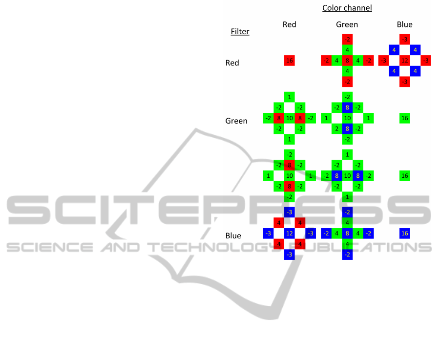
This is obtained by applying a pattern to the pixel
and its neighbors. The different patterns and their
respective pixel weights are shown in figure 2. The
pattern used is dependent on the filtered color of the
pixel and the desired color channel. For every pixel,
three patterns are applied (one for every color chan-
nel), where one pattern is trivial.
These patterns are designed to improve the result
around edges by incorporating the gradient of the lu-
minance values. When we calculate the green value
on a red filtered pixel, for example, we do not dis-
card the red value. The red value is used to calcu-
late the luminance change (using adjacent red values)
and this is incorporated when calculating the green
value. Thus, we calculate the bilinear interpolation of
the green pixels around the red filtered pixel and use
the red filtered pixels to correct this interpolation for
edges. The same principle holds for different color
channels.
Figure 2: Convolution filters for demosaicing. The choice
of filter is based on the desired color channel for that pixel
(column) and the filter used for that pixel (row).
These patterns can easily be used as finite impulse
response (FIR) filters and implemented as such.
3 CUDA ARCHITECTURE
To obtain real-time demosaicing of images, we use
commodity GPUs for processing. More specifically,
we use the CUDA framework provided by NVIDIA.
Nowadays, commodity GPUs are exposed as a col-
lection of single-instruction multiple-thread (SIMT)
streaming processors, which easily allows parallel
general purpose applications. To use these GPUs
for general purpose applications, the algorithm must
be split up in elementary threads that all execute the
same code, but on different data. All threads share a
block of off-chip global memory, which is accessible
by the host CPU. The access to this global memory
is slow and should be avoided as much as possible.
To allow optimization, different threads are grouped
together in blocks, where it is possible to reuse data
loaded from global memory by using a type of shared
memory. Access to the shared memory is fast, but
limited to a block. All blocks have different shared
memories and no fast communication between blocks
is therefore possible.
RawCameraImageDemosaicingusingFiniteImpulseResponseFilteringonCommodityGPUHardwareusingCUDA
97
This paradigm is consistently mapped to the GPU
hardware. The GPU is a collection of multiproces-
sors, where each multiprocessor contains one instruc-
tion decoder, but multiple streaming processors. Each
streaming processor in a multiprocessor thus executes
the same instruction, but using different data. All
multiprocessors contain a local on-chip fast mem-
ory, accessible by all streaming processors. Every
multiprocessor is furthermore connected to an off-
chip GPU-wide memory block using a relatively slow
memory bus.
Every block of the execution model maps on one
multiprocessor and every thread of a block can be ex-
ecuted by one streaming processor. Because it is pos-
sible to have more threads in a block than there are
streaming processors available, a thread scheduler is
available to suspend and resume threads. The group
of threads that is executed simultaneously is called a
warp, and is well-defined by the number of stream-
ing processors to allow performance optimizations. It
is furthermore possible to have multiple blocks reside
on a single multiprocessor. These blocks are com-
pletely separated from each other and can not com-
municate in any faster way as blocks on different mul-
tiprocessors can communicate.
Because this distributed shared memory architec-
ture is well-known, it is possible to optimize the algo-
rithm for maximum performance. Firstly, it is possi-
ble to coalesce memory accesses of the global mem-
ory of different threads in one memory call. This will
reduce the load on the memory bus and increase the
overall speed. Secondly, it is possible to optimize
the number of blocks and threads per block to as-
sure every processor is kept busy and no valuable pro-
cessor cycles are lost. The effective fraction of used
streaming processors is called the occupancy. Enough
blocks and threads should be defined to utilize every
streaming processor.
To increase occupancy, memory latency should be
hidden. Threads will become idle when waiting for
the results of a global memory fetch, which can take
hundreds of clock cycles. Therefore, the idle threads
can be swapped out and other threads can continue
their execution. Because the threads can also use data
from other threads in the same block, it will happen
that the majority of the threads are waiting on a few
threads, which in turn are waiting for the result of
their global memory fetch. To counter this idle pro-
cessor time, the multiprocessor can decide to fetch in
another block of threads. This is only possible when
the blocks are small enough to allow the presence of
multiple blocks on the multiprocessor.
The number of blocks per multiprocessor and the
number of threads per block is limited by the com-
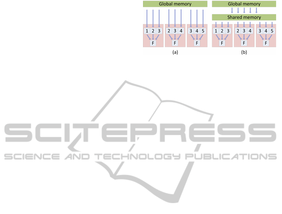
Figure 3: Implementation strategies for FIR filtering on par-
allel SIMT architectures. (a) Naive strategy. Every thread
fetches all required data, resulting in multiple slow memory
accesses per thread. (b) Optimized strategy. Every thread
fetches only one data element and stores this in a shared
memory. Because other threads fetch the other data ele-
ments, data reuse is possible, resulting in less slow memory
accesses.
pute capability of the hardware. More recent compute
capabilities allow more flexibility and more simulta-
neous threads, thus the optimizations are dependent
hereof.
4 IMPLEMENTATION
We implemented the method of (Malvar et al., 2004)
using CUDA. Because this method is a specialization
of generic FIR filtering, we will discuss this first.
4.1 Generic FIR Filtering
We can use the parallel direct GPU computing ar-
chitecture to implement linear FIR filtering with the
aid of a user-managed cache i.e. the shared memory
(Goorts et al., 2009). When implementing, for exam-
ple, a 3 × 3 filter without optimizations, we can al-
locate one thread for every pixel of the image. This
thread will access 9 pixels of the image in global
memory to calculate the final result for the allocated
pixel (see Figure 3 (a)). However, it is possible to re-
duce the memory accesses by reusing the information
of nearby threads, i.e. the thread loads only his allo-
cated pixel in shared memory and can then use the
values of nearby pixels which are loaded in shared
memory by other threads. Therefore, the amount of
global accesses per thread is reduced to one, which is
shown in Figure 3 (b).
Since the size of the blocks is limited and some
threads at the borders of the blocks don’t have enough
data available to calculate the filtered value, we must
create extra threads at the borders that only read pixel
informationand hereby will not calculate a newvalue.
This way, these threads won’t need the value for
neighboring threads. The set of these specific threads
is called the apron (see Figure 4).
SIGMAP2012-InternationalConferenceonSignalProcessingandMultimediaApplications
98
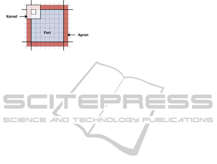
Figure 4: One block for filtering a part of the image. The
threads at the border (red) are inside the apron and do not
calculate new values for their pixels. They only load data
for use by the internal threads (blue).
4.2 FIR Filtering for Demosaicing
We have ported the demosaicing principles of (Malvar
et al., 2004) on the GPU using CUDA. The algorithm
is in essence a 2D linear FIR filtering. We already in-
vestigated FIR filtering using CUDA in our previous
research (Goorts et al., 2009). Because the kernels are
small, separating the kernels in 1D filters or using the
Fourier transforms will not result in a speedup. There-
fore, we will only use direct, straightforward filtering.
However, the effect of the number of threads per
block and the trade-off between the total size of the
apron and the occupancy must be investigated. When
we havea small amount of threads per block, the over-
all amount of threads in the aprons is large, and a lot
of accesses to global memory must be made. How-
ever, as the blocks are small, this allows for multiple
blocks per multiprocessor, and enough blocks to uti-
lize every available multiprocessor. When the number
of threads per block is large, the overall number of
threads in the aprons is smaller, but less blocks can be
defined and some multiprocessors can become idle or
no memory latency hiding can be employed. There-
fore, we will investigate what the optimal number of
threads per block is to maximize performance.
To avoid divergent branching, we defined a thread
per square of four pixels. This way, every thread will
process the same kind of data and no selection of the
filter is needed; every thread uses all 12 filters.
5 EXPERIMENTAL RESULTS
We performed our experiments on two devices using
CUDA version 4.1. The first device is an NVIDIA
GeForce 8800 GT with compute capability 1.1 and
112 streaming processors at 600 MHz; the second de-
vice is an NVIDIA GTX 580 with compute capability
2.0 and 512 streaming processors at 772 MHz. The
input images have a resolution of 1600× 1200. To
reduce the effects of low-level process management
by the operating system, we executed every configu-
ration 5000 times and computed the average running
time for a single execution.
We will present different results for both compute
capabilities to stress the effect of changes in the ar-
chitecture while it evolves to more advance massive
parallelism.
5.1 Compute Capability 1.1
The measured execution times of the different config-
urations are shown in Figure 5. In this graph, we only
discuss block widths that allow data coalescing; other
widths will result in uncoalesced reads and decrease
the performance severely.
Two effects are noticed: first, the general perfor-
mance for very small blocks is high. This is caused
by the occupancy of the multiprocessors; there are
enough blocks to fill every multiprocessor and the
memory footprint is small enough to allow multiple
blocks per multiprocessor. Multiple blocks per mul-
tiprocessor allow for effective hiding of the memory
latencies caused by starting fetches from global mem-
ory for other parallel threads. The performance is
higher compared with larger blocks, which is counter-
intuitive as smaller blocks result in increased number
of apron threads and thus more memory fetches.
The second effect is the almost constant execution
time after a certain block size (shown as the dotted
line on Figure 5). Increasing the block size will pre-
vent allocating multiple blocks to one multiprocessor,
and will hence decrease the performance. Neverthe-
less, when the blocks become larger, the overall num-
ber of threads in the aprons will decrease, simultane-
ously reducing the amount of global memory fetches.
Ergo, after the performance drop due to the reduced
occupancy, the performance will increase again, but
remains lower than small block sizes.
5.2 Compute Capability 2.0
The measured execution times of the different config-
urations are shown in Figure 6. The results are in-
terestingly different compared to compute capability
1.1; the most performant configuration is no longer
the smallest block size. The total number of simul-
taneous threads raises due to the increased warp size,
thus the total amount of simultaneous global memory
reads increases. The latency becomes too high to ef-
fectively hide it with more threads. Therefore, it is
better to reduce the total number of memory fetches
while keeping the occupancy as high as possible by
RawCameraImageDemosaicingusingFiniteImpulseResponseFilteringonCommodityGPUHardwareusingCUDA
99
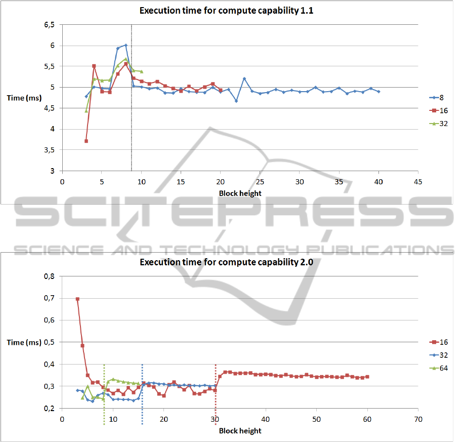
Figure 5: Results for compute capability 1.1. Every graph represents the width of the block, only considering coalesced
configurations. The height is varied on the horizontal axis.
Figure 6: Results for compute capability 2.0. Every graph represents the width of the block, only considering coalesced
configurations. The height is varied on the horizontal axis.
making sure that multiple blocks per multiprocessor
can be executed independently in succession.
Slightly increasing the block size does not de-
crease occupancy immediately. The specifications of
compute capability 2.0 provide more flexibility, thus
allowing larger block sizes. Therefore, we see a more
distinct effect on the occupancy, which is clearly visi-
ble in Figure 6. This phenomenon manifests for block
sizes of 64x9 (576 threads), 32x16 (512 threads) and
16x31 (496 threads), where the performancesuddenly
drops significant (shown as the dotted lines on Fig-
ure 6). The reason is that less blocks are allocated
per multiprocessor, thus impeding on the advantage
of memory latency hiding.
6 CONCLUSIONS
In this paper, we investigated the problem of demo-
saicing on CUDA using FIR convolution, and which
trade-offs must be made. We found that there is a
clear difference between compute capability 1.1 and
2.0, two of the most common CUDA hardware plat-
forms.
SIGMAP2012-InternationalConferenceonSignalProcessingandMultimediaApplications
100

Compute capability 1.1 has strict rules for coalesc-
ing and actual achievable occupancy. Therefore, it is
more performant to hide memory latency and raise
the performance by using small block sizes, even if
thereby the memory accesses increase significantly.
Compute capability 2.0 allows more simultaneous
threads and has more flexibility, thus automatically
increasing the occupancy by allowing more blocks
per multiprocessor. However, the throughput of the
threads is too high to effectively hide all memory
latency, thus occupancy is decreased for very small
block sizes. Therefore, the amount of memory fetches
can be decreased without affecting the occupancy,
which increases the performance. This is valid until a
specific threshold is reached. Crossing this threshold,
the number of blocks per multiprocessor decreases,
and the performance drops significantly.
These different results prove that the memory wall
for systems with slow memory and fast processors, as
stated by (Asanovic et al., 2006), still holds and that
the effect becomes more distinct when the individ-
ual processor capabilities increase, and the number of
processors increase faster than the speed of the mem-
ory. The trade-offs between processing and memory
accesses are important and must always be properly
investigated to reach maximum performance.
ACKNOWLEDGEMENTS
Patrik Goorts would like to thank the IWT for its PhD
specialization bursary.
REFERENCES
Asanovic, K., Bodik, R., Catanzaro, B. C., Gebis, J. J.,
Husbands, P., Keutzer, K., Patterson, D. A., Plishker,
W. L., Shalf, J., Williams, S. W., and Yelick, K. A.
(2006). The Landscape of Parallel Computing Re-
search: A View From Berkeley. Electrical Engineer-
ing and Computer Sciences, University of California
at Berkeley, 18(183):19.
Bayer, B. (1976). Color imaging array. US Patent
3,971,065.
Goorts, P., Rogmans, S., and Bekaert, P. (2009). Optimal
data distribution for versatile finite impulse response
filtering on next-generation graphics hardware using
cuda. In Parallel and Distributed Systems (ICPADS),
2009 15th International Conference on, pages 300–
307. IEEE.
Hirakawa, K. and Parks, T. (2005). Adaptive homogeneity-
directed demosaicing algorithm. Image Processing,
IEEE Transactions on, 14(3):360–369.
Laroche, C. and Prescott, M. (1994). Apparatus and method
for adaptively interpolating a full color image utilizing
chrominance gradients. US Patent 5,373,322.
Malvar, H., He, L., and Cutler, R. (2004). High-quality lin-
ear interpolation for demosaicing of bayer-patterned
color images. In Acoustics, Speech, and Signal Pro-
cessing, 2004. Proceedings.(ICASSP'04). IEEE Inter-
national Conference on, volume 3, pages 485–488.
IEEE.
McGuire, M. (2008). Efficient, high-quality bayer demo-
saic filtering on gpus. Journal of Graphics, GPU, and
Game Tools, 13(4):1–16.
RawCameraImageDemosaicingusingFiniteImpulseResponseFilteringonCommodityGPUHardwareusingCUDA
101
