
Semantics of Logical Relations in Topological Functioning Model
Uldis Donins
Department of Applied Computer Science, Institute of Applied Computer Systems, Riga Technical University,
Meza iela 1/3, LV 1048, Riga, Latvia
Keywords: Topological Modelling, Modelling Formalization, Logical Relations, Model Checking and Analysis.
Abstract: The Topological functioning model (TFM) captures system functioning specification in the form of
topological space consisting of functional features and cause-and-effect relations among them and is
represented in a form of directed graph. The formal foundation of TFM makes it as a primary model which
should be developed when implementing a software system. The functional features together with
topological relationships contain the necessary information to create diagrams of other type, e.g., Activity or
Communication diagrams. To specify the behaviour of system execution a new artefact is added to TFM –
logical relations. The presence of logical relations denotes forking, branching, decision making, and joining
during execution of system. Thus, it is needed to carefully analyse these new relations in TFM to have all
the necessary information to transform it to other diagrams. The paper concludes with an example of TFM
analysis and logical relationship identification within it.
1 INTRODUCTION
The way software is built still remains surprisingly
primitive (by meaning that major software
applications are cancelled, overrun their budgets and
schedules, and often have hazardously bad quality
levels when released) (Jones, 2009). This is due that
the very beginning of software development
lifecycle is too fuzzy and lacking a good structure
since the software developers have limited analysis
and modelling of systems (Donins and Osis, 2011).
Instead of analysing the system software developers
set the main focus on analysis and modelling of
software thus leading to a gap between the system
and its supporting software (Osis and Asnina, 2008).
This issue can be overcome by formalizing the very
beginning of the software development lifecycle
(Donins and Osis, 2011).
By having too fuzzy beginning of the software
development and lacking a good structure of it, for
example, the CIM-to-PIM (Computation
independent model to Platform independent model)
conversion in the context of Model Driven
Architecture (MDA) (Miller and Mukerji, 2003)
depends much on designers’ personal experience
and knowledge. Thus the quality of PIM cannot be
well controlled (Osis et al., 2007). There are a
number of researches (e.g., (Debnath et al., 2008))
which try to enforce the initial phase in software
development by strengthening it with various
models like use cases (Yue et al., 2009), goal based
models (Letier, van Lamsweerde, 2002), behavioral
models (Diaz et al., 2005), and structural models
(Insfran et al., 2002).
In (Asnina, 2009) a transformation from TFM to
“simple” Unified Modeling Language’s (UML)
(OMG, 2011) Activity diagrams consisting of action
nodes and edges is shown. The word “simple” is
used while the (Asnina, 2009) states that “it is
impossible to create fork and join nodes
automatically because the TFM does not hold
information of concurrency”. This research
introduces a new element in TFM – logical relations
which hold im-portant information when
transforming TFM into other diagram types, for
example, Activity or Use Case diagrams. The
analysis of logical relations within TFM helps to
validate causality between functional features and
the logic embedded in TFM. The logical relations
contains information of decision making and
concurrency thus allowing to formally define
decision, merge, fork, and join nodes while
transforming TFM into Activity diagram.
This paper is organized into following sections.
Section 2 gives mathematical foundations of TFM
together with formal definitions of its elements
217
Donins U..
Semantics of Logical Relations in Topological Functioning Model.
DOI: 10.5220/0004088002170223
In Proceedings of the 7th International Conference on Evaluation of Novel Approaches to Software Engineering (MDA&MDSD-2012), pages 217-223
ISBN: 978-989-8565-13-6
Copyright
c
2012 SCITEPRESS (Science and Technology Publications, Lda.)
(including the logical relations). Section 3 explores
semantics of logical relations in TFM and gives
method together with example on identification of
these relations. Section 4 gives a method of TFM to
Activity diagram transformation. In addition it
shows an example of formal Activity diagram
development. The paper is concluded with
conclusions of this research which sketches also
future research directions.
2 MATHEMATICAL
FOUNDATIONS OF
TOPOLOGICAL
FUNCTIONING MODEL AND
LOGICAL RELATIONS
The TFM holistically represents a complete
functionality of the system from the computation
independent viewpoint (in the context of MDA). It
considers problem domain information separate
from the solution domain information. The TFM is
an expressive and powerful instrument for a clear
presentation and formal analysis of system
functioning and the environment the system works
within. This means that the TFM of the system
validates functional requirements and can be
partially changed by those requirements. (Osis and
Asnina, 2011) and (Osis and Donins, 2010)
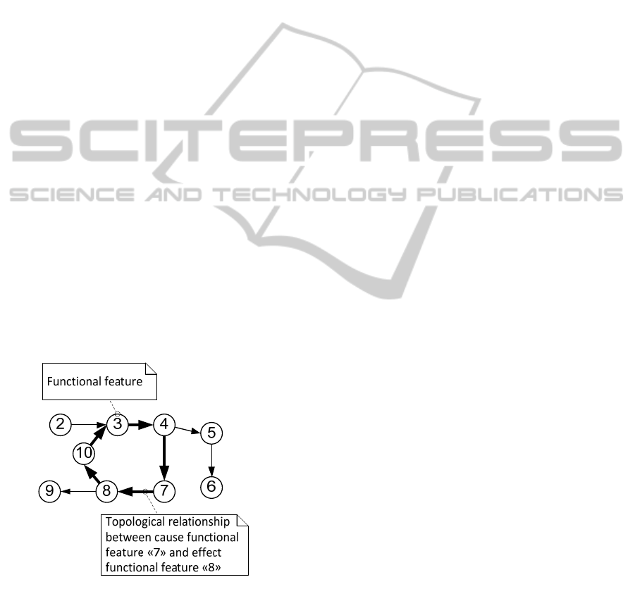
An example of TFM is given below in Figure 1.
Figure 1: Example of Topological Functioning Model.
TFM has strong mathematical basis and is represented
in a form of a topological space. The TFM has four
topological characteristics: connectedness, closure,
neighbourhood, and continuous mapping; and four
functional characteristics: cause-effect relations, cycle
structure, and inputs and outputs. TFM enables
careful analysis of system’s operation and
communication with the environment through
analysis of functional cycles. (Osis and Asnina,
2011).
While the formal definition of TFM (functional
features, topological space, closure operation) is
well defined in (Osis and Asnina, 2011) and
functional features in (Osis and Donins, 2010) this
paper formally defines pre- and post- conditions of
functional features, cause-and-effect (i.e.,
topological) relationships, and the new element
within TFM – the logical relations.
2.1 Definition of Topological
Functioning Model Elements
Formal Definition of Preconditions and
Postconditions. Each precondition or post-condition
is a condition Cid described by unique tuple given in
equation (1). Condition can be considered as an
atomic business rule.
C
i
d
= <Id, Cond, oCond>, where (1)
Id – identifier of condition,
Cond – condition or an atomic business rule,
and
oCond – identifier of opposite condition, i.e., C
i
= ¬C
j
(optional).
Formal Definition of Topological Relationships.
Cause-and-effect relationship Tid is a binary
relationship relating two functional features Xid and
are represented as arcs of a directed graph that are
oriented from a cause vertex to an effect vertex. The
synonym for cause-and-effect relationship is
topological relationship. Each cause-and-effect
relationship is a unique tuple represented by
equation (2):
T
i
d
= <Id, X
c
, X
e
, L
ou
t
, L
in
>, where (2)
Id – unique identifier of topological relation,
X
c
– cause functional feature,
X
e
– effect functional feature,
L
out
– set of logical relationships between
topological relationships on outgoing arcs of
cause functional feature X
c
(optional), and
L
in
– set of logical relationships between
topological relationships on incoming arcs of
effect functional feature X
e
(optional).
Formal Definition of Logical Relations. Logical
relation Lid shows the logical rela-tionship
conjunction (and), disjunction (or), or exclusive or
ENASE2012-7thInternationalConferenceonEvaluationofNovelSoftwareApproachestoSoftwareEngineering
218
(xor) between two or more topological relationships
Tid. The type of logical relation denotes system
execution behavior (e.g., decision making, parallel
actions). Each logical relation is a unique tuple
represented by equation (3):
L
i
d
= <Id, T, Rt>, where (3)
Id – identifier of logical relationship,
T – set of topological relationships belonging to
this logical relationship, and
Rt – logical relationship type (and, or, or xor).
Identification of logical relations L
id
between
cause-and-effect (i.e., topological) relationships T
id
consists of two activities:
1) identification of logical relations L
out
between
topological relationships T
id
that are outgoing
from functional feature X
id
(see Section 3.1),
and
2) identification of logical relations L
in
between
topological relationships T
id
that are incoming
to functional feature X
id
(see Section 3.2).
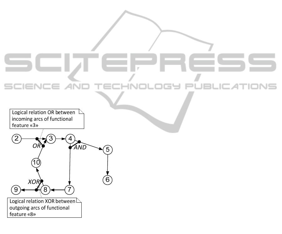
Example of logical relations between topological
relationships is given in Figure 2.
Figure 2: Example of logical relations between topological
relationships.
2.2 Application of Topological
Functioning Model
Construction of TFM can be iterative. Iterations are
needed if the information collected for TFM
development is incomplete or inconsistent or there
have been introduced changes in system functioning
or in software requirements. The development of
TFM consists of four steps. Within previous
researches (Osis et al., 2008) there are defined three
steps (step 1 to step 3) for developing TFM of
system functioning. This research adds fourth step –
identification of logical relations. The steps of TFM
development are as follows:
1) Definition of functional characteristics –
functional features,
2) Introduction of topology Θ, which means
establishing cause-and-effect relationships
between functional features (i.e., development
of topological space),
3) Separation of TFM X from the topological
space, by applying the closure operation over a
set of system’s inner functional features, and
4) Identification of logical relations L
in
and L
out
within TFM.
The identification of logical relations makes
additional check of correctness of developed TFM.
There might be situation when conflicting logical
relations are identified. If such situation arises then it
is needed to review and refine TFM in order to
eliminate conflicting logical relations. Refinement of
TFM can include addition of functional features and
topological relationships, or redefinition of pre- and
post- conditions.
3 LOGICAL RELATIONS
BETWEEN TOPOLOGICAL
RELATIONSHIPS
Between topological relationships exist two kinds of
logical relationships – one kind is between arcs that
are outgoing from functional features and the other
kind is between arcs that are incoming to functional
features. The logical relationships between outgoing
arcs are denoted with L
out
and the logical
relationships between incoming arcs – L
in
. Logical
relations L
out
indicates necessity of decision making
or branching. In the case of making decision only
part of effect functional features X
id
is executed, but
in the case of branching all of the effect functional
features X
id
are executed (i.e., system performs
parallel processing); while logical relations L
in
indicates that there are decision or branching made
before the effect functional feature X
id
. If there was
branching before the effect functional feature X
id
,
then before executing this functional feature there
should be joining and system can continue its
execution only after all arcs are joined. This reflects
the mathematical foundations of Petri nets (Desel
and Juhás, 2001).
Within TFM can be defined three types of logical
relations L
id
: conjunction (and), disjunction (or), and
SemanticsofLogicalRelationsinTopologicalFunctioningModel
219
exclusive or (xor). Within each logical relation L
id
can participate two or more topological relationships
T
id
. The following two subsections cover the
identification of logical relations L
out
and L
in
.
3.1 Relations between Outgoing Arcs
Depending on the relationship type Rt of logical
relation L
id
on outgoing topological relationships T
id
from cause functional feature X
c
, system execution
behaviour is defined as follows:
AND – system executes in parallel by executing
all functional features X
e
of topological
relationships T
i
participating in this logical
relation L
id
,
OR – system can be executed in parallel by
executing one, part of or all functional features
X
e
of topological relationships T
i
participating
in this logical relation L
id
, and
XOR – only one functional feature X
e
of
topological relationships T
id
participating in this
logical relation L
id
is executed.
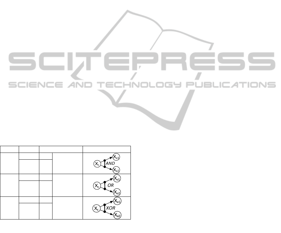
The rules for identification of logical relations
L
out
between outgoing arcs of functional features are
given in Table 1, where Rt denotes relation type, X
e
– effect functional features, and C
id
– preconditions
of X
e
.
Table 1: Rules for identification of logical relations Lout
between outgoing arcs.
Rt X
e
C
id
Example of L
id
AND
X
e1
Ø
X
e2
Ø
OR
X
e1
C
1
C
1
≠ C
2
&
C
1
≠ ¬C
2
X
e2
C
2
XOR
X
e1
C
1
C
2
= ¬C
1
X
e2
C
2
The logical relations L
out
contains necessary
information within TFM that denotes decision
making and forking in problem domain workflows.
Thus the logical relations L
out
should be analyzed
and identified before the TFM transformation into
Activity diagram.
3.2 Relations between Incoming Arcs
Depending on the relationship type Rt of logical
relation L
id
on incoming topological relationships T
id
of effect functional feature X
e
, system execution
behavior is defined as follows:
AND – system is executing in parallel thus
effect functional feature X
e
can be executed
only when all direct predecessor functional
features (i.e., all cause functional features X
c
in
the distance d=1) of topological relationships T
i
participating in logical relation L
id
are executed,
OR – system can be executing in parallel by
executing one, part of or all cause functional
features X
c
of effect functional feature X
e
at the
distance d=1 of topological relationships T
i
participating in this logical relation, and
XOR – only one cause functional feature X
c
of
effect functional feature X
e
at the distance d=1
of topological relationships T
id
participating in
this logical relation L
id
is executed.
Relation type Rt of logical relations L
in
is
denoted by corresponding logical relation L
out
and
the inputs and outputs of TFM (this defines the base
rule set for identifying L
in
). Additional rule is used
for definition of logical relation which contains both
topological relationships connecting input functional
feature (can be a chain of input functional feature)
with other functional features of TFM and
topological relationships connecting functional
features within TFM. In such situation a logical
relation with type OR is added.
The logical relations L
in
contains necessary
information within TFM that denotes merging (after
decision making) and joining in problem domain
workflows. Thus the logical relations L
in
should be
analysed and identified before the TFM
transformation into Activity diagram.
3.3 Example of Logical Relationships
Identification
To better illustrate identification of TFM logical
relations a case study is used in which an enterprise
data synchronization system is developed (Donins
and Osis, 2011). The case study includes
development of TFM (without analysis of logical
relations), Use Case, Sequence, and Topological
class diagram development, while this research
analyses logical relations within developed TFM and
investigates formal development of Activity
diagrams. Within case study have been defined 30
functional features. After definition of functional
features the topology Θ (cause-and-effect
relationships) are identified between those functional
features thus creating topological space representing
functioning of the problem domain and relations
with external environment.
In order to get all of the system’s functionality –
the set X – the closuring operation (Osis, Asnina,
ENASE2012-7thInternationalConferenceonEvaluationofNovelSoftwareApproachestoSoftwareEngineering
220
2011) is applied over the set of internal system
functional features (the set N). The obtained TFM
(the set X) after applying closuring operation is as
follows: X={2, 3, 5, 6, 7, 8, 9, 11, 12, 13, 14, 15, 16,
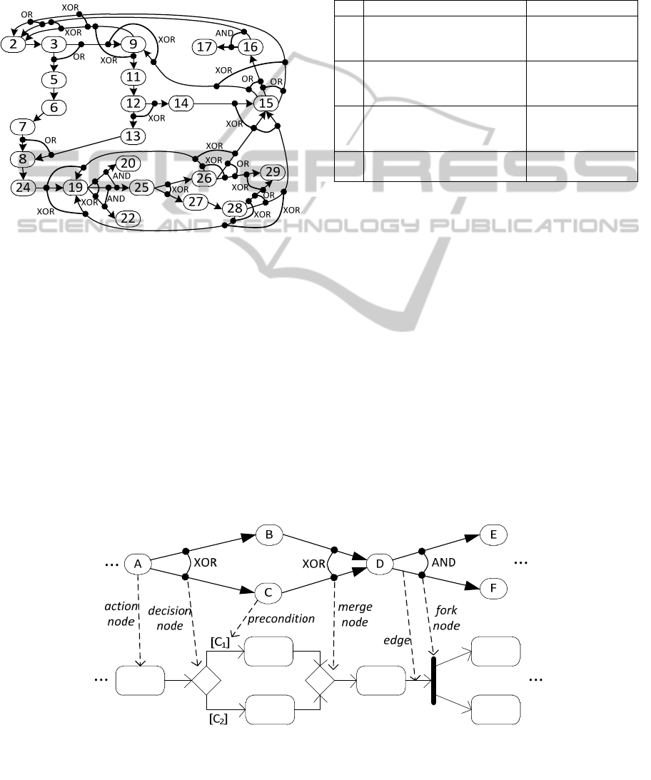
17, 19, 20, 22, 24, 25, 26, 27, 28, 29}. The resulting
graph is given in Figure 3 which shows functional
features (vertices), cause-and-effect relationships
(arcs between vertices), and logical relations.
Figure 3: TFM representing enterprise data
synchronization system functioning and logical relations
between cause-and-effect relationships.
To better understand identification of logical
relations a small fragment of TFM given in Figure 3
is used consisting of four functional features: 19, 20,
22, and 25 (see Table 2). The functional feature 20
has a precondition C
1
(“If data from the particular
row exists”) and functional feature 22 has a
precondition C
2
(“If data from the particular row
does not exist”) while functional feature 25 has no
preconditions.
The relation between preconditions C
1
and C
2
is
as follows: C
1
= ¬C
2
; thus indicating that between
the arcs that are outgoing from feature 19 to features
20 and 22 (19→20 and 19→22) the logical relation
with type exclusive disjunction (XOR) exist. Since
functional feature 25 has no preconditions a logical
relations with type conjunction (AND) is added
between topological relationship 19→20 and
19→25, and 19→22 and 19→25.
Table 2: Part of functional features defined for enterprise
data synchronization system.
ID Object Action Precondition
19
Checking if data from a
particular row already exists
in target data base
-
20
Updating existing data in
target data base
If data from the
particular row
exists
22
Insert new data in target
data base
If data from the
particular row
does not exist
25
Logging data row from
temporal table
-
4 APPLICATION OF TFM
LOGICAL RELATIONS
Application of TFM logical relations within
topological functioning modelling allows formally
developing Activity diagrams representing
workflows in problem domain. The input of this
activity is Use Cases, TFM, and mappings between
functional features and functional requirements. The
scope of each Activity diagram is set by the scope of
corresponding Use case (i.e., the Activity diagram
contains the description of the same functionality
that is included into corresponding Use Case).
The TFM and mappings between functional
features and Use cases allows establishing actions
and the control flow between actions – functional
features are transformed into action nodes and
Figure 4: Example of TFM to Activity diagram transformation.
SemanticsofLogicalRelationsinTopologicalFunctioningModel
221
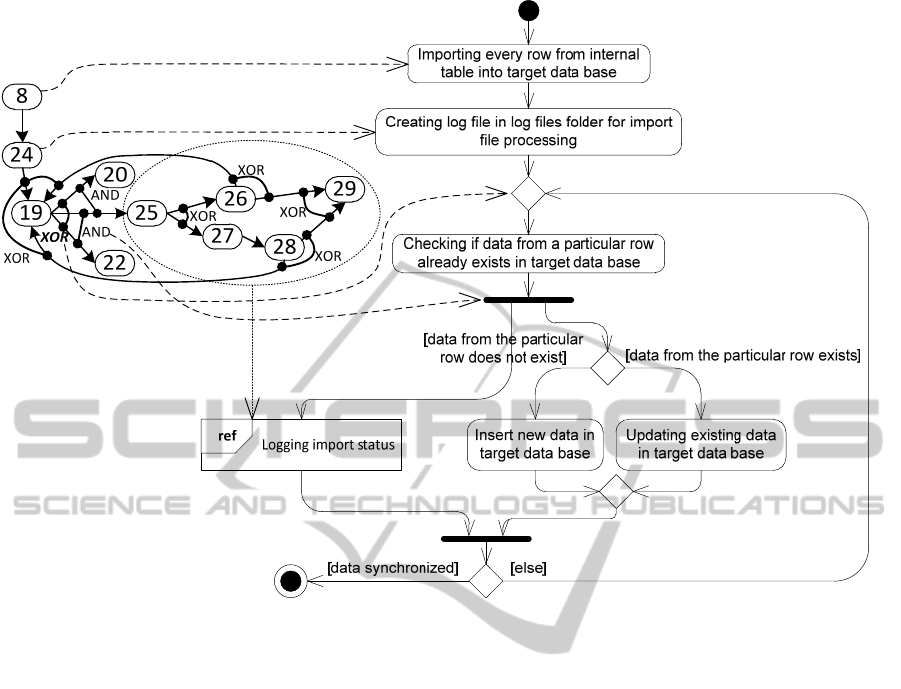
Figure 5: Part of TFM representing functioning of enterprise data synchronization system and activity diagram representing
workflow of Use Case “Importing data in target data base”.
topological relationships into activity edges.
The logic of control flow (i.e., decision, merge,
fork, and join) is defined in accordance with the
TFM logical relations. While depending on the type
of logical relation L
out
fork node (for relation type
and) and decision node (for relation types or and
xor) is added to Activity diagram, the type of logical
relations L
in
denotes join node (for relation type and)
and merge node (for relation types or and xor)
addition to the Activity diagram. Figure 4 gives an
example of TFM to Activity diagram transformation.
In the context of Use Case diagram these logical
relations defines «include» and «extend»
relationships between Use Cases. Thus by using
logical relations it is possible to build advanced
Activity and Use Case diagrams. This is in
opposition to the opinion in (Donins and Osis, 2011)
that TFM contains information sufficient to create
only basic Activity diagrams (i.e., without fork and
join nodes).
4.1 Example of Formally Developing
Activity Diagram
To better illustrate formal analysis of problem
domain workflows a case study is used described in
Section 3.3 is used. According to the mappings
between functional features and requirements and
logical relations in TFM the «include» and «extend»
relationships are automatically established between
Use Cases (Donins and Osis, 2011). The scope and
count of activity diagrams are denoted by the Use
cases and their mappings with functional features.
According to the defined Use cases and established
mapping, a total set of seven Activity diagrams is
created. Activity diagram representing the use case
“Importing data in target data base” is given in
Figure 5 showing the part of TFM that is
transformed into Activity diagram and a trace links
from elements of TFM to elements of Activity
diagram. As FR1/5 mappings includes also
functional requirement FR1/6, the corresponding
Activity diagram contains interaction use to Activity
diagram “Logging import status”. The mappings
between functional requirements FR1/5, FR1/6, and
functional features are as follows:
FR1/5 “Importing data in target data base” =
{8, 24, 19, 20, 22, FR1/6}; and
FR1/6 “Logging import status” = {25, 26, 27,
28, 29}.
ENASE2012-7thInternationalConferenceonEvaluationofNovelSoftwareApproachestoSoftwareEngineering
222

5 CONCLUSIONS
This research introduces a new element into TFM –
logical relations. Logical relations in TFM are
crucial when transforming TFM into other diagrams.
Thus the analysis of logical relations takes an
important part of TFM development and problem
domain specification. Within each logical relation
can participate two or more logical relationships and
each logical relation has its type – conjunction (and),
disjunction (or), or exclusive or (xor). Logical
relations exist between topological relationships and
denote the system functioning behavior. Depending
on logical relation type system functioning behavior
is specified by means of decision making, merging,
forking, and joining. While depending on the type of
logical relation L
out
fork node (for relation type and)
and decision node (for relation types or and xor) is
added to Activity diagram, the type of logical
relations L
in
denotes join node (for relation type and)
and merge node (for relation types or and xor)
addition to the Activity diagram.
In addition this research shows that by adding
additional efforts at the very beginning of software
development life cycle it is possible to create a
model that contains sufficient and accurate
information of problem domain. By “sufficient”
meaning that this model can be transformed into
other diagrams without major re-analysis of problem
domain and by “accurate” meaning that the model
precisely reflects the functioning and structure of the
system.
ACKNOWLEDGEMENTS
This work has been supported by the European
Social Fund within the project “Support for the
implementation of doctoral studies at Riga Technical
University”.
REFERENCES
Asnina, E., 2009. A Formal Holistic Outline for Domain
Modeling. In 13th East-European Conference (ADBIS
2009), Associated Workshops and Doctoral
Consortium, Local Proceedings (pp. 400-407). JUMI
publishing house.
Debnath, N., Leonardi, M., Mauco, M., Montejano, G.,
Riesco, D., 2008. Improving Model Driven
Architecture with Requirements Models. In 5th
International Conference on Information Technology:
New Generations (ITNG 2008) (pp. 21-26).
Desel, J., Juhás, G., 2001. What is a Petri Net? Informal
Answers for the Informed Readers. In Unifying Petri
Nets, Advances in Petri Nets, Lecture Notes in
Computer Science (LNCS) Vol.2128 (pp. 1-25).
Springer-Verlag.
Diaz, I., Pastor, O., Matteo, A., 2005. Modeling
Interactions using Role-Driven Patterns. In IEEE
International Conference on Requirements
Engineering (pp. 209-220).
Donins, U., Osis, J., 2011. Topological Modeling for
Enterprise Data Synchronization System: A Case
Study of Topological Model-Driven Software
Development. In 13th International Conference on
Enterprise Information Systems (ICEIS 2011) (pp. 87-
96). SciTePress.
Insfran, E., Pastor, O., Wieringa, R., 2002. Requirements
Engineering-Based Conceptual Modelling.
Requirements Engineering, 7(2), pp. 61-72.
Jones, C., 2009. Positive and Negative Innovations in
Software Engineering. International Journal of
Software Science and Computational Intelligence,
1(2), pp. 20-30.
Letier, E., van Lamsweerde, A., 2002. Deriving
Operational Software Specifications from System
Goals. In the 10th ACM SIGSOFT Symposium on
Foundations of Software Engineering (pp. 119-128).
ACM.
Miller, J., Mukerji, J. (eds), 2003. MDA Guide Version
1.0.1. OMG.
OMG, 2011. Unified Modeling Language Infrastructure
version 2.4.1. OMG.
Osis, J., Asnina, E., 2008. A Business Model to Make
Software Development Less Intuitive. In the
International Conference on Innovation in Software
Engineering, Vienna, Austria. IEEE Computer Society
CPS (pp. 1240-1246).
Osis, J., Asnina, E., 2011. Model-Driven Domain Analysis
and Software Development: Architectures and
Functions, IGI Global, USA.
Osis, J., Asnina, E., Grave, A., 2007. Computation
Independent Modeling within the MDA. In IEEE
International Conference on Software Science,
Technology and Engineering, 30-31 October 2007,
Herzlia, Israel, IEEE Computer Society Nr. E3021
(pp. 22-34).
Osis, J., Asnina, E., Grave, A., 2008. Computation
Independent Representation of the Problem Domain in
MDA. e-Informatica Software Engineering Journal,
2(1), pp. 29-46.
Osis, J., Donins, U., 2010. Formalization of the UML
Class Diagrams. In Evaluation of Novel Approaches to
Software Engineering. Communications in Computer
and Information Science (CCIS), Vol. 69 (pp. 180-
192). Springer-Verlag.
Yue, T., Briand, L., Labiche, Y., 2009. A Use Case
Modeling Approach to Facilitate the Transition
towards Analysis Models: Concepts and Empirical
Evaluation. In Model Driven Engineering Languages
& Systems. Lecture Notes in Computer Science
(LNCS) Vol.5795 (pp.484-498). Springer-Verlag.
SemanticsofLogicalRelationsinTopologicalFunctioningModel
223
