
Modelling and Simulation of Human-like Movements
for Humanoid Robots
Parvin Abedi
1
and Ali Leylavi Shoushtari
1,2
1
Department of Computer Engineering, Shoushtar Branch, Islamic Azad University, Shoushtar, Iran
2
Department of Mechatronics, South Tehran Branch, Islamic Azad University, Tehran, Iran
Keywords: Human Body Dynamics, Humanoid Robots, Optimization-based Simulation.
Abstract: The humanoid robots are bio-inspired models of human body. The mechanical structure of humanoid robots
consists of several joints and segments. Numerous degrees of freedom are caused the redundancy problem.
There is an unanswered question concerning with strategies which central nervous system implements to
predict the human posture and gesture during different movements. A 7 degree of freedom model is used for
modelling humanoid robot and an optimization-based method is planned to simulation of human motion.
The joints angles and torques are subjected as optimization variables. The joints range of motion and limits
of actuator torques are used as optimization constraints. The weight lifting is the motion which is subjected
to simulation. Finally the results presented for two velocity lifting. The result shows the body posture varies
naturally and the weight maintain at the end position at final time correctly.
1 INTRODUCTION
Digital human modelling is used in an extensive field
of researches such as robotics, biomechatronics,
ergonomics etc (Blajer et al., 2007; Xiang et al.,
2010), because it can implement for calculating the
parameters that are not possible to measure like:
torques and internal forces of joints and stress
exerted to joint's soft tissues. An important usage of
modelling of human body is dynamic analysis of
humanoid robots (Arisumi et al., 2007).
For understanding how the human-like
movements planned for a humanoid robot, it is so
important to know how the redundancy problem
solved by central nervous system. In order to know
how the body postures varies during different
movements to construct motion animation of human
body, a model of whole human body dynamics
applied to movement simulation process. Simulation
and analysis of human movements commonly used
for athletics in order to improve performance of the
motion and so prevent injuries in cause of incorrect
movements (Demircan et al., 2009).
Biomechatronical model with large number of
degree of freedom needed to done the human motion
simulation more exactly and accurately. The
multiplicity of joint space variables (DOFs) causes
model manoeuvrable but creates redundancy
problem. We face with the redundancy problem
when the number of DOFs is more than needed to
perform a task. Both kinematic and dynamic
redundancy is problems with wide range of solutions
in some areas of researches as robotics biomechanics.
The robot manipulators with redundant degrees of
freedom are able to done different tasks skilfully
(Wang et al., 2010; Park et al., 2001). Human body
models usually contained large number of DOFs. For
applying these models to motion simulation,
optimization-based approaches are good methods to
overcome with the redundancy problem. Some of
these techniques are applied to robotic manipulator
models with redundant DOFs (Schafer et al., 2003;
Oh et al., 1997; Wang et al., 2010). Optimization-
based solutions are suitable ways to solve problem
with large number of variables, because this method
uses a few amount of data as inputs to result a large
number of variables as output set (Guran et al.,
2012). The input contains two set of constraints
impose to motion simulation process: 1. Constraints
obtained from motion dynamics and 2. Variety
limitation of optimized variables would be
optimized. The second type used as inequality
constraints and the first one contain some algebraic
and differential equations.
CNS arranges the task with the balanced
movements. Walking, sitting, running and lifting are
342
Abedi P. and Leylavi Shoushtari A..
Modelling and Simulation of Human-like Movements for Humanoid Robots.
DOI: 10.5220/0004094903420346
In Proceedings of the 9th International Conference on Informatics in Control, Automation and Robotics (ICINCO-2012), pages 342-346
ISBN: 978-989-8565-21-1
Copyright
c
2012 SCITEPRESS (Science and Technology Publications, Lda.)

good examples of tasks related to daily living
activities performed completely balanced
involuntarily. CNS uses an unknown algorithm to
manage tasks unconsciously. Optimization-based
simulation methods have performance analogous
with CNS function caused balanced movements.
These approaches used objective function description
subjected to minimizing which is duality of CNS
algorithm manner. On the other hand to simulate a
movement as like as shape that biological system
does, it assumed that optimization approach
minimized the objective function considered that
CNS try to minimize it too.
Ankle torque amplitude considered as criteria of
stability and the optimization algorithm tries to
minimize summation of ankle torque squares during
lifting time. A seven DOF biomechatronical model
of whole human body represented in part 2 obtained
from kinematical modeling based on D-H method
(Denavit and Hartenberg, 1995; Siciliano and Khatib,
2008; Khatib et al., 2009). Based on Lagrangian
method, the equations of motion are formulated in
inverse dynamics form. In section 3 simulation
process is described and in sections 4 and 5 presents
the simulation results and the conclusion
respectively.
2 MODELLING OF HUMAN
BODY
A planar model with 7DOF in sagittal plane
implemented in represents coordination system of
human body (Figure 1). All the limbs as shank, thigh,
lumbar, thoracic and cervical spine, arm and forearm
subjected to modelling and considered as rigid bars
with mass points at center of mass of each link which
named: l
,l
,l
,l
,l
,l
,l
respectively. For human
major joints as ankle, knee, hip, shoulder and elbow
had considered joint angles in modelling to figurate
human body posture and represented by the
names:
,
,
,
,
respectively. The box
assumed jointed to human body at the wrist with a
horizontal orientation. Biomechatronical models of
human body with coordination systems illustrated by
fig. 2. Human body dynamics commonly model as a
kinematics chain like robot manipulators, so the
method which is used to modeling the dynamics of
motion of human body, is like ones used for robotic
manipulators.
Figure 1: 7DOF model of human body with Denavit-
Hartenberg coordination systems which is attached to each
link.
The inverse dynamics form of equations of motion of
a kinematical chain is presented as bellow
(
)
̈ +(,̇)̇ +()=Γ
(1)
In (1)
(
)
is 7×7 matrix related to mass and
inertial properties of the model (Xiang et al., 2009)
and Γ is 7×1 generalized joints torque vector.
(,̇) is a term related to centrifugal and coriolis
forces and () is gravitational forces vector, this
term calculates as (2) and (3).
(
,̇
)
=
̇
(
)
−
1
2
̇
(
)
(2)
()=
(3)
Generalized joint torque represented in (1) divided in
two parts: 1. torques resulted in muscle forces and 2.
torques due to the box load exerted on wrist. These
kinds obtain as (4):
Γ =
−
!
;
!
="
#
$
!
%
&
(4)
In (4) "
is transpose of Jacobean matrix which
project box load to joints $
'*-
is box mass and %
is transpose of gravity force vector.
3 OPTIMIZATION-BASED
SIMULATION
In this paper lifting movement simulation considered
as optimization problem which CNS do either. In this
problem an objective function subjected to be
optimized with some constraints which limit the
motions boundary to a feasible range to construct
motion naturally. In other words it's being assumed
that CNS try to minimize a particular function value
to perform each task, and musculoskeletal system
impose some constraints to the motion too.
Modelling and Simulation of Human-like Movements for Humanoid Robots
343
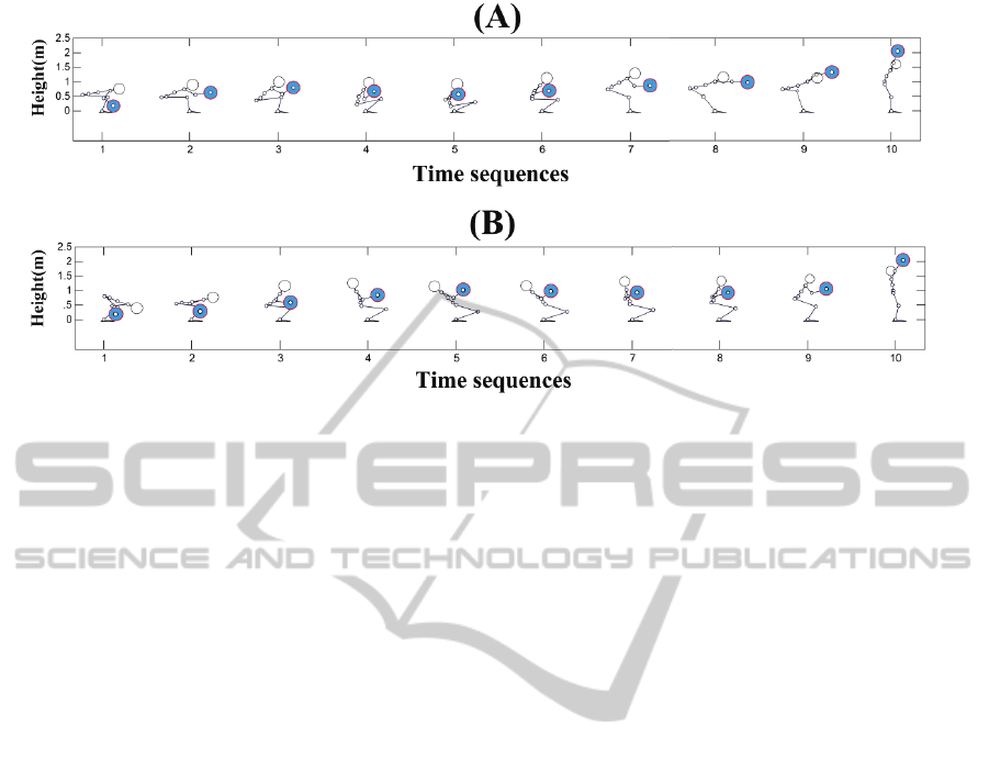
Figure 2: Body postures of humanoid robot, during lifting task for two lifting time: A) 3 second and B) 2.5 second. The
horizontal axis is time in term of second, by scaling 0.3 second for (A) and 0.25 second for (B).
Predictive dynamics is a novel approach used to
motion simulation (Xiang et al., 2010; Xiang et al.,
2009). It implements inverse dynamics as a major
constraint to modeling the dynamics of the motion in
the simulation process. The joints torques and angles
selected as the optimization variables, so by using
this method we can obtain joint angles and torques as
output according to task parameters used as inputs
(Guran et al., 2012). Simulation elements are
described in bellow sections.
3.1 Objective Function
By considering the lifting task as a simple inverted
pendulum motion, represents represent a simple
model to analysis the stability of motion. In other
hand If lifting motion models as a inverted pendulum
(Demircan et al., 2009) it can says that magnitude of
torque of pendulum joint, has direct relation to
amount of deviation from stability position (.=0
°
).
Therefore we can use of a particular function which
constructed in term of ankle torque as motion
stability index. It proposes this function as integral of
ankle torque squares in each time sequence (5).
/
(
,,3
)
=4
568
93
!:<
(5)
3.2 Constraints
The constraints used in this research are: joints
torques and angles limitations, initial and final
position of box, elevating constraint, inverse
dynamics, and body collision avoidance constraint
which is used for prevent of collision box with body
(Denavit, 1995).
−
6>?
=0 ;
6>?
=@
(
,3
)
(6)
In equation (6) is joints torque vector should be
predicted, and
6>?
is joints torque vector obtained
from inverse dynamics. Body collision avoidance
implemented in this simulation is a systematic
method to check the penetration value of the box into
the body in each iteration of optimization process. It
is used to determine horizontal position of the box to
collision avoidance adaptively.
The collision avoidance considered in
optimization process as a constraint to prevent
penetration of box with the body. It’s inequality
constraint and defined as a term of sufficient
horizontal distance 9A which wrist should move to
prevent collision box with the body.
4 RESULTS
The optimization process designed for 10 evenly
distributed time sequences. Inertial properties
considered as data used previously (Guran et al.,
2012). The optimization process ran for two lifting
times 2sec, 2.5 sec and 3 sec.
An index presented to evaluate the motion
stability during all the time sequences. Total moment
arm (TMA) of all the links are calculated as (7) it's
calculated from the moments respect to all of the
links weight for each configuration related to time
sequence. $
5
is total weight of body and A
(
3
)
is
horizontal position of B′3ℎ links at time 3, and D is
number of links. Optimized joint angles show that
how the body posture varies during lifting task, it
ICINCO 2012 - 9th International Conference on Informatics in Control, Automation and Robotics
344
illustrated in figure 2.
EFG
(
3
)
=
1
$
5
H$
A
(
3
)
I
:
(7)
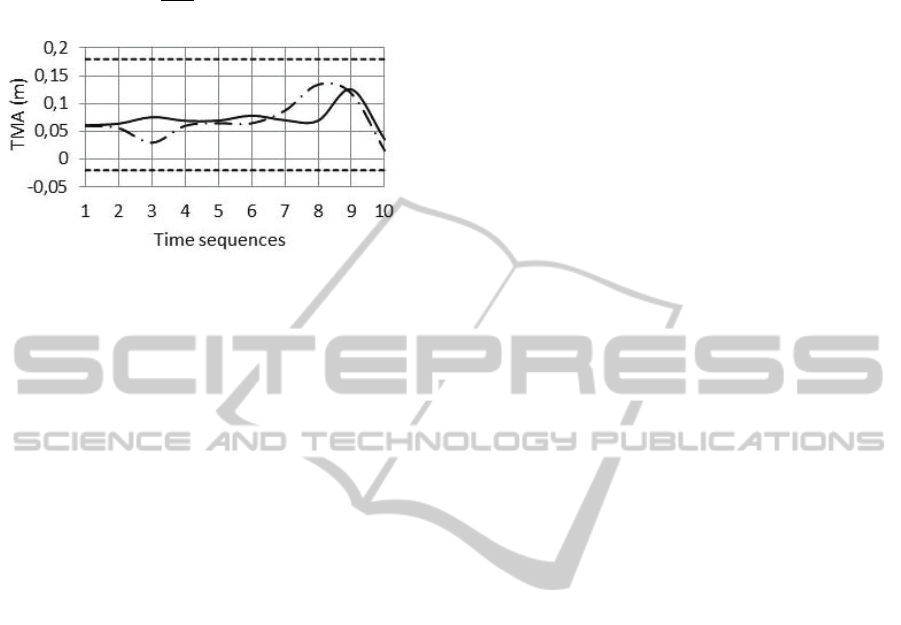
Figure 3: TMA values for two lifting times (2.5 sec for
solid line and 3 sec for broken one) during lifting time. To
prevent falling forward or backward, TMA values should
be restricted between base of support (distance between
heel and toe). These two boundaries are shown as dashed
lines at TMA=-.02 (m) and TMA =0.18 (m).
5 CONCLUSIONS
Simulation process implements 7DOF
biomechatronical model of human body to simulate
weight lifting motion by using predictive dynamics
approach. The constraints which applied to this
process, limit motion space to a feasible region that
human limbs move through it. Major constraint
named inverse dynamic, implement the dynamics of
the motion in simulation process and finally the
optimized postures shaped by objective function
minimization. Figure 2 Shows that posture variation
does in a natural shape. The box motion is extremely
uprising, and it situates at initial and final position
exactly and also it hasn't collision to the body in all
of the postures. The motion of weight started at its
first position and ended at the final position correctly.
The wrist is mounted at centre of mass of weight in
sagittal plane. The results show that this position
never collided with the body. The motion of the
weight is uprising.
Figure 3 illustrate the TMA values during lifting
time and its boundaries. According to this figure,
Lifting movement performed completely balanced
because TMA have values between upper and lower
boundaries. In other words minimizing ankle torque
summation can guarantee motion balancing
.
REFERENCES
Blajer W., Dziewiecki K., Mazur Z., 2007. Multibody
modeling of human body for the inverse dynamics
analysis of sagittal plane movements. Multibody
systems Dynamics. 18(2). pp. 217-232.
Xiang Y., Arora J. S., Rahmatalla S., Marler T., Bhatt R.,
Abdel-Malek K., 2010. Human lifting simulation using
a multi-objective optimization approach. Multibody
Dynamics. 23(4). pp. 431-451.
Arisumi H., Chardonnet J. R., Kheddar A., Yokoi K. 2007.
Dynamic Lifting Motion of Humanoid Robots. IEEE
International Conference on Robotics and Automation.
Rome. Italy.
Demircan E., Khatib O., Wheeler J., Delp S., 2009.
Reconstruction and EMG-Informed Control,
Simulation and Analysis of Human Movement for
Athletics: Performance Improvement and Injury
Prevention. Proc. IEEE international conference on
Engineering in Medicine and Biology Society.
Minneapolis. MN. pp. 6534-6537.
Wang J., Li Y., Zhao Z., 2010. Inverse Kinematics and
Control of a 7-DOF Redundant Manipulator Based on
the Closed-Loop Algorithm. International journal of
Advanced Robotic System. 7(4). pp. 1-12.
Park K. C., Chang P. H., Lee S., 2001. Analysis and
control of redundant manipulator dynamics based on an
extended operational space. Robotica. 19(6). pp. 649-
662.
Schafer B., Krenn R., Rebele B., 2003. On inverse
kinematics and kinetics of redundant space manipulator
simulation. Journal of Computational and Applied
Mechanics. 4(1). pp. 53-70.
Peters J., Mistry M., Udwadia F., Nakanishi J., Schaal S.,
2007. A unifying framework for robot control with
redundant DOFs. Autonomous Robots. 24(1). pp. 1-12.
Oh Y., Chung W., Youm Y., Suh I. H., 1997. A Passive-
based motion control of redundant manipulators using
weighted decomposition of joint space. Proceeding
IEEE International Conference on Robotic and
Automation. Monterey. CA. pp. 125-131.
Zhang Y., Zhu H., Tan Z., Cai B., Yang Z., 2008. Self-
motion planning of redundant robot manipulators based
on quadratic program and shown via PA10 example.
Proceeding IEEE 2nd International Symposium on
Systems and Control in Aerospace and Astronautics,
Shenzhen. pp. 1-6.
Wang J., Li Y., Zhao X., 2010. Inverse Kinematics and
Control of a 7-DOF Redundant Manipulator Based on
the Closed-Loop Algorithm. International journal of
Advanced Robotic Systems. 7(4). pp. 1-10.
Guran A., Iqbal K., Shoushtari A., 2012. Biomechatronical
Motion Simulation of Human Lifting using a Novel
approach to Solve Kinematic Redundancy in Human
Movements. Euromech colloquium 538, Physics of
sports, Paris.
Denavit J., Hartenberg R. S., 1995. A kinematic notation
for lower-pair mechanisms based on matrices.
Transaction of ASME Journal of Applied Mechanics.
23. pp. 215–221.
Siciliano B., Khatib O., 2008. Springer handbook of
robotics. 1st edition. Springer publication.
Modelling and Simulation of Human-like Movements for Humanoid Robots
345
Khatib O., Demircan E., De Sapio V., Sentic L., Besier T.,
Delp S., 2009. Robotic-based Syntesis of human
motion. Journal of physiology-Paris. 103(3-5). pp.
211-219.
Spong M. W., Vidyasagar M., 1989. Robot Dynamics and
Control. John Wiley and Sons, Inc.
Xiang Y., Arora J. S., Rahmatalla S., Abdel-Malek K.,
2009. Optimization-based dynamic human walking
prediction: one step formulation. International Journal
for Numerical Methods in Engineering. 79(6). pp. 667–
695.
APPENDIX
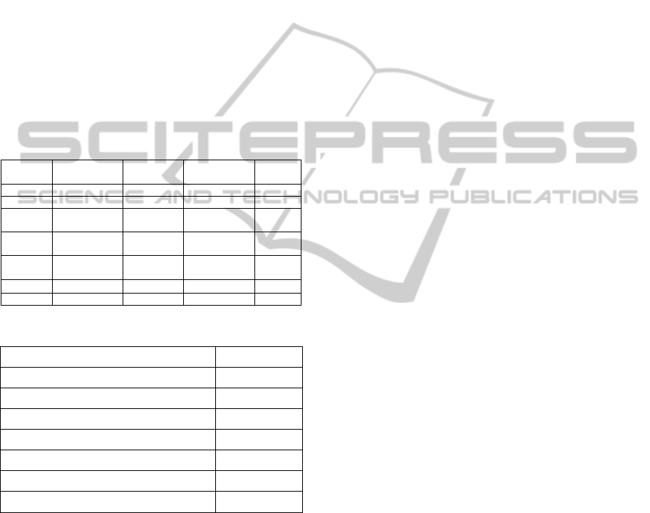
The parameters of lifting task and lifter's body which
subjected to simulation are presented in table1 and
table 2 respectively.
Table 1: Parameters of lifter's body and related values.
Mass
(kg)
Inertia
(N.J
K
)
COM (m)
Length (m)
8
1
0.24
0.48
shank
20.8
1.7
0.22
0.44
hip
6
1.0
0.05
0.10
Lumbar
spine
7.9
1.3
0.09
0.18
Thoraci
c spine
11
1.4
0.105
0.21
Cervica
l spine
3.8
0.7
0.14
0.28
arm
3.2
1.34
0.15
0.30
forearm
Table 2: Parameters of lifting task and related values.
Parameters Values
Weight
40 kg
Initial horizontal position of
COM of weight
0.20 m
Initial vertical position of COM of weight
0.18 m
Final horizontal position of COM of
weight
0.1 m
Final vertical position of
COM of weight
1.95 m
Lifting time
2.5 and 3 (sec)
Number of time sequences 10
ICINCO 2012 - 9th International Conference on Informatics in Control, Automation and Robotics
346
