
A Compositional Scheme and Framework for Safety
Critical Systems Verification
Manuel I. Capel
1
and Luis E. Mendoza-Morales
2
1
Department of Software Engineering, Informatics & Telecomunications Bldg.,
University of Granada, 18071 Granada, Spain
2
Processes and Systems Department, Sim´on Bol´ıvar University,
P.O. box 89000, Baruta, Caracas 1080-A, Venezuela
Abstract. Safety–Critical Systems (SCS) mustsatisfy dependability requirements
such as availability, reliability, and real-time constraints, in order to justify the
reliance of the critical service they deliver. A verification framework named For-
mal Compositional Verification Approach (FCVA)is presented here. FCVA estab-
lishes a compositional method to verify safety, fairness and deadlock absence of
SCS. Software components of a given critical system are model–checked to ver-
ify the aforementioned properties. Our objective in this paper is to facilitate the
design of an SCS from a collection of verified simpler components, and hence al-
lowing complete complex SCS software verification. An application on a real–life
project in the field of mobile phone communication is discussed to demonstrate
the applicability of FCVA.
1 Introduction
Safety–Critical Systems (SCS), including energy production, automotive, medical sys-
tems, avionics, modern telecommunications . . ., they are industrial systems where avail-
ability, performance, safety and the other dependability attributes should justify the re-
liance on the critical service they deliver to their customers. The baseline for obtaining
a verifiable design of SCS is to previously develop a specification of the target system
using at least one formal language to perform the subsequent verification of the system.
Based on component abstraction and system modularity, advanced Model–Checking
(MC) techniques [1],[2], have become an active area of research, and are frequently
used to uncover well–hidden bugs in sizeable industrial SCS (see Table 1). How-
ever, SCS automatic verification can be impeded by the state explosion problem that
a model checker tool has to tackle when the system model is huge and complex [3],[4],
[5],[6],[7],[8].
The objective here is to facilitate the description of an SCS as a collection of sim-
pler verified components, then allowing the verification of safety, fairness and deadlock
absence of a complex SCS software.
However, it becomes very difficult to export local verification results using a for-
mal language with conjunctive propositional logic operators, and preserve, at the same
time, the semantic correctness of these demonstrations when they are compound. In
I. Capel M. and E. Mendoza-Morales L..
A Compositional Scheme and Framework for Safety Critical Systems Verification.
DOI: 10.5220/0004097300150026
In Proceedings of the 10th International Workshop on Modelling, Simulation, Verification and Validation of Enterprise Information Systems and 1st
International Workshop on Web Intelligence (MSVVEIS-2012), pages 15-26
ISBN: 978-989-8565-14-3
Copyright
c
2012 SCITEPRESS (Science and Technology Publications, Lda.)

our view, the lack of compositionality that automatic verification techniques exhibit is
mainly due to semantic and syntactical problems, caused by the incorrect integration of
different specification formalisms, i.e., property specification languages (CTL, ACTL,
etc.) and modelling notations based on states (formal automata, Promela, etc.), which,
depending on the formal combination language, may induce semantic errors in the sys-
tem’s verification. So far, the notational integration and semantical integration has not
been solved.
A unique underlying common semantic domain, within which the different spec-
ification formalisms used in SCS verification are interpreted, may help to obtain the
desired compositionality of verified system components.Therefore, a new Formal Com-
positional Verification Approach (FCVA) is proposed to verify a SCS from individual
components, based on a conceptual framework that transforms the model and proper-
ties of the SCS into a CSP–based formal language. An automatable instance of our
framework FCVA is introduced [9],[10]. FCVA gives a methodological infrastructure
for verification made up of: (1) a formal specification/modelling notation supported
by CSP–based compositional reasoning that enables the preservation of the compo-
nent properties throughout the compositionality to be demonstrated, and (2) conceptual
hooks that facilitate the integration of CSP–based MC tools into the verification process.
The paper is organized as follows. In the following section the formal background to
our approach is described. Afterwards, the conceptual framework behind the FCVA is
presented, followed by a complete description of how the FCVA is designed. Thereafter,
we demonstrate the value and practicality of our approach through the application on
a real–life project in the field of mobile phone communications, which has to meet
critical time requirements. Finally, in the last section, our conclusions and future work
are discussed.
Table 1. Main characteristics of related work.
Formalism Work Strategy Properties Tool Encapsulation
[4]
Model the environment using additional interface
processes.
Liveness, Mutual exclu-
sion. Limited to loosely
coupled systems.
No Yes
[6]
Propose a preorder for use with a subset of CTL*.
Safety, simple liveness,
and a notion of fairness.
Ad-hoc No
[3]
Incrementally refinement using partial models. Safety and liveness.
Ad-hoc No
[11]
MC to deal with control issues and deductive
method to handle data-intensive elements.
Safety.
SPIN Yes
Automata
[5]
Incremental assume-guarantee reasoning. Safety.
LTSA Yes
[12]
Compose complex software systems from domain–
specific patterns.
Safety.
RAVEN Yes
[13]
Modular analysis based on the Assump-
tion/Commitment method.
Safety.
HyTech No
[7]
Propose a modular verification approach. Safety.
SMV No
[14]
Automatically generating component assumptions
based on the behaviour of the environment.
Do not specify.
SPIN Yes
[8]
Using the equivalence relation among processes.
Deadlock, Starvation,
and Parallelism.
Ad-hoc Yes
Process
[15]
Presents a simple formulation of AGR using CSP. Safety.
FDR Yes
Algebra
[16]
Proposes a compositional technique for traces re-
finement checking.
Safety.
FDR Yes
[17]
Constructing decompositions to efficient AGR. Safety.
FDR Yes
2 Formal Background
The essence of safety–critical processes behaviour and the sequence and communica-
16

tion synchronization that it should represent are described by CSP [18] and CSP+T [19]
models in our proposed method.
2.1 Specification of the System Model
CSP+T is a real–time specification language which extends Communicating Sequential
Processes (CSP) allowing the description of complex event timings, within a single
sequential process.
A CSP+T process term P is defined as a tuple (αP, P ), where αP = Comm act(P )∪
Interface(P ) is called the communication alphabet of P . These communications rep-
resent the events that process P receives from its environment or those that occur in-
ternally. CSP+T is a superset of CSP, the latter being changed by the fact that traces of
events become pairs denoted as t.a, where t is the time at which event a is observed.
where a, ⋆ ∈ Σ (communication alphabet); A, N ⊆ Σ; v ∈ M (marker variables);
I ∈ I (time intervals); P, Q, X,
e
P ∈ P (process names); t
0
, t
a
, t
1
∈ T ; and T ∈ N
(time instants), and the function s(t
a
.a) which return the occurrence time of symbol a.
Table 2. CSP+T Syntax Rules.
SKIP :≡ success (successful termination)
ST OP :≡ deadlock
t
a
.a → P :≡ t
a
.a then P (prefix)
t0.⋆ →
e
P :≡ (⋆ ∧ s(⋆) = t0) then
e
P
(process instantiation)
t
a
.a ⋊⋉ v → P :≡ (t
a
.a ∧ s(a) = t
a
) then P
(marker variable)
P # Q :≡ P (successfully) followed by Q
(sequential composition)
P ⊓ Q :≡ P or Q
(non–deterministic)
P Q :≡ P choice Q
(deterministic or external choice)
P \A :≡ P without A
(hidding)
P △Q :≡ P interrupted by Q
I(T, t
1
).a → P :≡ (t
a
.a ∧ t
a
∈ [rel(t
1
, v),
r el(t
1
+ T, v)]) then P
(event–enabling interval)
I(T, t
1
) →
e
P :≡ t > rel(t
1
+ T, v ) then
e
P (delay)
P kQ :≡ P in parallel with Q
(parallel composition)
P |[A]|Q :≡ P in parallel with Q
in alphabet A (alphabetized composition)
P 9 Q :≡ P interleave Q (interleaving)
I(T
a
, t
a
).a → P |[A]|
I(T
b
, t
b
).b → Q :≡ P kQ if (a = b)∧
(I(T
a
, t
a
) ∩ I(T
b
, t
b
) 6= ∅)
:≡ P 9 Q if (a 6= b)∧
(I(T
a
, t
a
) ∩ I(T
b
, t
b
) 6= ∅)
:≡ ST OP if I(T
a
, t
a
)
∩I(T
b
, t
b
) = ∅
µX@P :≡ the process X such that
X = P (X) (recursion)
e
m
i=1
: N • P (i) :≡ i : N → P (i)
(external choice indexed)
d
m
i=1
: N • P (i) :≡ P ((τ−)action)
(internal choice indexed)
g
m
i=1
: N • P (i) :≡ i : N →
g
m
i=1
P (i)
(indexed interleaving)
f
m
i=1
[A] : N • P (i) :≡ i : N →
f
m
i=1
P (i)
(partial interleaving)
f
m
i=1
: N • A(i) ◦ P (i) :≡ i : N →
f
m
i=1
A(i) ◦ P (i)
(parallel combination)
The event enabling interval I(T, t
a
) = {t ∈ T |rel(t
a
, v) ≤ t ≤ rel(t
a
+ T, v)}
indicates the time span where any event is accepted. rel(x, v) = x + v − t
0
, t
0
corre-
sponds to the preceding instantiation event (⋆), occurred at some absolute time t
0
, and
x is the value held in the marker variable v at that time. The time interval expression
can be simplified to I(T, t
a
) = [t
a
, t
a
+ T ] if the instantiation event, after which the
event a can occur, corresponds to the origin (t
0
= 0) of the rt-clock.
2.2 Abstract Specification of the Properties
Property specification languages are used to obtain a formal specification of the ex-
pected SCS behaviour according to the user requirements. CCTL [20] is a temporal
17

{ϕ,¬ψ}
S
1
{ψ}
S
2
[a+1,b]
{}
S
0
[a,b-1]
[a+1,b-1]
[a+2,b]
Fig.1. CCTL formula.
interval logic that extends Computation Tree Logic (CTL) with quantitative bounded
temporal operators, i.e., temporal operators interpreted over time intervals. CCTL is
used to deal with sequences of states, where a state gives a temporal interpretation of a
set of atomic propositions (AP) at a certain time interval and time instants are isomor-
phic to the set of non–negative integers.
CCTL includes CTL with the operators until (U) and the operator next (X) and other
derived operators in LTL, such as release (R), weak until (W), cancel (C) and since
(S). All of them have proved to be useful to facilitate the definition of the properties
included in reactive systems classes —such as the SCS one— requirements specifica-
tion. All “LTL-like” temporal operators are preceded by a run quantifier (A universal,
E existential) which determines whether the temporal operator must be interpreted over
one run (existential quantification) or over every run (universal quantification). These
temporal operators start in the current configuration. For instance, let φ be the CCTL
formula 1 which states that ψ must become true within the interval [a, b] and, that
the formula ϕ must be valid at all previous time steps. The CCTL specification of the
formula φ in Figure 1 is therefore:
φ = ϕU
[a,b]
ψ . (1)
2.3 Transformation Rules
The formalisation of UML–RT given by MEDISTAM–RT [21] is of interest here be-
cause it allows us to obtain and verify a SCS model from UML diagrams. MEDISTAM–
RT (acronym of Method for System Design based on Analytic Transformation of Real–
Time Models) can be described as a series of system views represented by UML for Real
Time (UML–RT) with class diagrams, composite structure diagrams, and UML timed
state machines (UML–TSM). The expressiveness of UML state–machines (UML–SM)
is augmented by including new modelling constructs adopted from CSP+T syntax, such
that TSMs make now possible to model timing issues and time dependencies among
tasks. Table 3 shows a graphical example of the transformation rules application for
obtaining CSP+T process terms from UML–TSMs. We will only present one of the
proposed rules, mainly to demonstrate the applicability of FCVA and to show that our
approach can be integrated to MC tools like FDR2. A complete description of the sys-
tem of transformation rules can be found in [21].
The application of the transformation rules’ pattern:
event/communication/execution step)
premises
conclusion
(conditions) (2)
18
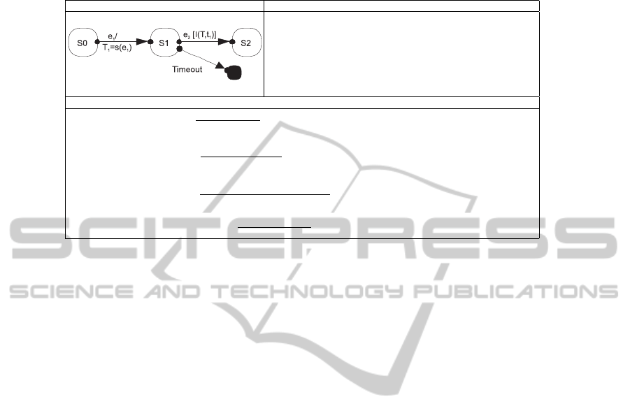
Table 3. Example of a map rule from UML–TSM to CSP+T terms.
UML–TSM Description
The state S1 precedes the state S2 and these states are reached when
eventse
1
and e
2
occur,respectively. But to reach the state S2, the event
e
2
(restricted event) must occur within the time interval [T 1, T 1+ T ]
(event–enabling interval), where T
1
is the maker variable of the event
e
1
(marker event). If the restricted event e
2
does not occur within the
time interval [T 1, T 1+T ] (i.e., the event–enabling intervalcompletely
runs), then reaches a pseudostate Timeout. T
1
, T ∈ N
∗
(i.e., natural
numbers without zero).
CSP+T Structural Operational Semantics
1. e
1
occurrence)
S1=e
1
⋊⋉t
1
→S2
t
1
=s(e
1
); S2
S1, S2 ∈ states;
s(e
1
)
2. e
2
occurrence)
S2=I(T ,t
1
).e
2
→S3
s(e
2
); S3
s(e
2
) ∈ [t
1
, t
1
+ T ];
S2, S3 ∈ states
OR
I(T, t
1
) timeout)
S2=I(T ,t
1
)→T imeout→SKI P
s(τ); T imeout→SKIP
s(τ ) < t
1
+ T ; S2 ∈ states;
T imeout ∈ pseudostates
T imeout execution step)
T imeout→SKIP
s(τ); SKIP
s(τ ) = t
1
+ T ;
T imeout ∈ pseudostates
can be understood as a transformation between two syntactical terms that occur as a
consequence of a communication between concurrent processes or an execution step or
event occurrence in a sequential process. Thus, each rule defines the premises of the
UML–RT element to be transformed and the conditions that must be satisfied before
transforming the referred element into the syntactical CSP+T process term indicated in
the conclusion of the rule.
3 Compositional Verification of SCS
Compositional verification of properties for a given temporal logic has recently been
studied intensively by several authors [12],[22], in order to solve a fundamental problem
of practical application of MC techniques to the verification of software systems.
A compositional scheme can be applied to the verification of temporal formulae
that express the certainty of a future event or system action (safety), or to verify that
the system is not undergoing a deadlock situation or to affirm that every needed state of
the system must be eventually entered in an infinite computation (fairness) (see Table
4). In contrast, Temporal Logic (TL) formulas that express the possibility of entering in
a state in the future (reachability) are not preserved by compositionality, nor properties
expressing that something is unavoidable in the future provided that some other thing
occurs (liveness) .
3.1 Compositional Verification of a Concurrent System
FCVA is aimed at performing compositional verification of behavioral properties of
SCS. In a formal way, the system model C is assumed to be structured into several
verified software components working in parallel, i.e., C =
f
i:1..n
C
i
, where each C
i
satisfies the property φ
i
, i.e., C
i
φ
i
, which represents the specification of the ex-
pected behaviour of the component. Regarding the proposed decomposition strategy,
19

Table 4. Verification–compositionality (VC) of different properties.
Name TL–denotation Fulfils VC?
Safety AG Yes
Liveness AG(req → AFsat)) No
Reachability EFφ No
Deadlock freeness AGEXtrue Yes
Fairness AGAFφ Yes
we assume that C can be decomposed until a set of components, whose behaviour can
be specified using a TSM, is found. In addition to the local properties φ
i
, each C
i
must
also satisfy the invariant expression ψ
i
that represents the behaviour of other system
components with respect to C
i
. Since, according to [23], to verify the property φ
i
of
component C
i
we need to assume the other components’ behaviour (i.e., ψ
i
).
Theorem 1: System Compositional Verification. Let the system C be structured into
several components working in parallel, C =
f
i:1..n
C
i
. For a set of T SM(C
i
) de-
scribing the behaviour of components C
i
, properties φ
i
, invariants ψ
i
, and deadlock δ,
with
T
i:1..n
Σ
i
= ∅,
T
i:1..n
Ω
i
= ∅, and
T
i:1..n
L(T BA(C
i
)) = ∅, the following
condition holds:
T SM(C) (φ ∧ ψ ∧ ¬δ) ⇔
n
i:1..n
T SM(C
i
)
^
i:1..n
(φ
i
∧ ψ
i
) ∧ ¬δ, (3)
where T BA(C) = k
i:1..n
T BA(C
i
).
Interpretation of SCV Theorem. If the properties used to specify the system com-
ponents are circumscribed to the class of composable properties for verification (see
Table 4), then property φ and the invariant ψ that are satisfied by the system C can be
obtained by conjunction of local properties φ
i
(i.e.,
V
i:1..n
φ
i
⇒ φ) and invariants ψ
i
(i.e.,
V
i:1..n
ψ
i
⇒ ψ), respectively. The special symbol ¬δ is used to denote deadlock
absence, i.e., a state without any outgoing transition cannot be reached on any system
execution.
3.2 Formal Compositional Verification Approach
Based on previous concepts and ideas, we propose a possible instantiation of the con-
ceptual scheme called FCVA. The rationale of FCVA is that the behavioural correctness
of SCS software components can be individually verified, in isolation, based on Theo-
rem 1 and the well–definedcommunicationsbehaviour specified by UML/MEDISTAM–
RT capsule component [21]. Methodologically, our approach establishes that both the
formal description of the system’s behaviour and the specification of its properties must
be directed by the system’s user requirements. And thus, FCVA consists of the follow-
ing integrated processes according to MC technique and the automata theory:
System Interpretation. Firstly, the complete description of the system’s behaviour,
modelled by the CSP+T process term T (C) is interpreted into a set of CSP+T
process terms T (C
i
) by using MEDISTAM–RT [21].
20

Properties Specification. Then, requirements and temporal constraints that the sys-
tem must fulfill are specified in CCTL, which is based on the interval structure
and time–annotated automata [20]. Afterwards, these properties are expressed by
CSP+T process terms T (φ
i
), T (ψ
i
), T (¬δ), following the algorithm described in
[9]. In this way, we translate the properties to the same semantic domain of the
system model in order to perform the verification process.
Verification. Finally, we proceed to verify the system behaviour component by com-
ponent.
Thus, we take advantage of formal specification/modelling notations supported by
CSP–based compositional reasoning that enables the preservation of the component
properties throughout the compositionality.
Fig.2. Graphical model of a DDBM communication protocol (in [24]).
4 Application
The application of FCVA presented here relates to monitoring the state of mobile de-
vices within the cells that constitute a mobile phone communication network.
We present a simple case study, but conceptually relevant. It is real–life scenario
where five BTSs
3
(A to E) exchange messages between them, i.e., SndMsg(s); acknowl-
edgement message, AckMsg(s); and receive confirmation, RcvConf(s).
The DDBM model shown in Figure 2 represents the functioning of a small dis-
tributed database system, which is needed to keep consistent the communication in-
formation locally stored in the base stations. Each site contains a copy of the entire
database and this copy is handled by a replicated local data base manager (DDBM =
k
i:1..n
d
i
). When a manager d
i
makes an update to its own copy, it must send a message
(denoted as SndMsg(s)) to all the other managers to ensure consistency between the n
copies of the data base, d
i
: SndM sg(s) = {(s, r)|s, r ∈ DDBM ∧ s 6= r}.
To understand the model of this DDBM communication protocol, we need to think
of it as a set of finite state automata with symmetries. The automaton on Figure 2 rep-
resents n symmetric replicated automata that describe the states (ellipses)of the n man-
agers d
i
and the state of the messages (rectangles) transmitted by each d
i
during DDBM
protocol functioning. The transitions that each automaton must undergo are represented
3
Base Transceiver Stations
21
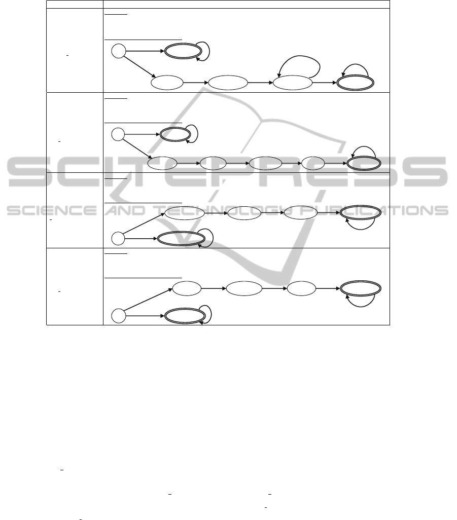
Table 5. Properties for components that implements the DDBM communication protocol.
Property Specification
(a) Remote update
request by
Act
Control
(RUAC)
Formula:
φ
RU AC
:= AG
[a,b]
(Snd1(s) → A[SndMsgL(s) U
[a+1,b−1]
(
V
x:1..n−1
AckM sgR(s
x
) ∧
A[
V
x:1..n−1
AckM sgR(s
x
) U
[a+1,b]
ConfR(s)])])
TBA semantically equivalent
:
{}
S
0
[a+1,b-2]
{Snd1(s)}
[a,b-1]
{¬Snd1(s)}
S
3
{SndMsgL(s)} {AckMsgR(s)}
Snd
[a+1,b]
[a,b-3]
[a+2,b-1]
SndMsgL AckMsgR
{ConfR(s)}
[a+3,b]
[a+4,b]
ConfR
AckMsgR
n-2
[a+3,b-1]
(b) Remote update
request by
Message
Manager
(RUMM)
Formula:
φ
RU MM
:= AG
[a,b]
(Up(s) → A[Snd2(s) U
[a+1,b−2]
(ConfR(s) ∧
A[ConfR(s) U
[a+2,b−1]
(Ack2(s) ∧ A[Ack2(s) U
[a+3,b]
Ready(s)])])])
TBA semantically equivalent
:
{¬Up(s)}
[a,b-1]
[a+1,b]
{}
S
0
[a+1,b-3]
{Up(s)}
{Ready(s)}
{Snd2(s)} {ConfR2(s)} {Ack(s)}
Up
[a,b-4]
[a+2,b-2] [a+3,b-1]
[a+4,b]
[a+5,b]
Snd
AckConfR
Ready
(c) Local update by
Act
Control(LUAC)
Formula:
φ
LU AC
:= AG
[a,b]
(SndM sgR(s) → A[Rcv1(s) U
[a+1,b−2]
(ConfL(s) ∧
A[ConfL(s) U
[a+2,b−1]
(AckM sgL(s) ∧ A[AckM sgL(s) U
[a+3,b]
RcvConf L(s)])])])
TBA semantically equivalent
:
{}
{SndMsgR(s)}
S
1
{¬SndMsgR(s)}
[a,b-1]
[a,b-3]
{Rcv1(s)}
S
1
SndMsgR
[a+1,b]
[a+1,b-2]
[a+2,b-1]
Rcv
{ConfL1(s)}
S
1
{AckMsgL(s)}
S
4
[a+3,b]
[a+4,b]
ConfL
AckMsgL
(d) Local response
by Message
Manager
(LUMM)
Formula:
φ
LU MM
:= AG
[a,b]
(Rcv2(s) → A[LocU p(s) U
[a+1,b−1]
(Upd(s) ∧
A[Upd(s) U
[a+2,b]
ConfL(s)])])
TBA semantically equivalent
:
{}
{Rcv2(s)}
[a,b-3]
{LocUp(s)} {Upd(s)}
{ConfL2(s)}
Rcv
[a+1,b-2]
[a+2,b-1] [a+3,b]
[a+4,b]
LocUp Upd
ConfL
[a,b-1]
{¬Rcv2(s)}
[a+1,b]
by rhomboids named, ‘Update and Send Messages’, ‘Receive a Message’, ‘Send an
Acknowledgement’ and ‘Receive All Confirmations’.
4.1 Properties Specification
The complete set of CCTL formulas that formally define the properties fulfilled by the
DDBM model’s behaviour are detailed in [9] and derived from user’s requirements. Ta-
ble 5 shows the interpretation of the property φ, expressing the guarantee of processing
one message at a time, according to the DDBM ‘Active’ and ‘Passive’ states, respec-
tively. When a d
i
manager enters the ‘Active’ state (i.e., request a remote update), the
Act Control component must engage in a sequence of events that corresponds with
the fulfillment of properties (a)-(d) set in Table 5. Therefore, the properties that express
the expected behaviour of Act Control and M essage M anager components can be
expressed as conjunctions of simpler properties, φ
Act Control
= φ
RUAC
∧ φ
LUAC
and
φ
Message Manager
= φ
RUMM
∧ φ
LUMM
, respectively. Since the DDBM protocol model
is conformed by n replicas of the same component (i.e., DDBM = k
i:1..n
d
i
), the in-
22

variant ψ
i
that each component d
i
must satisfy is the conjunction of the properties of
the n replicas, but without itself, i.e., ψ
i
=k
j:1..n
φ
j
|j 6= i, we need not include the
invariants ψ
i
as part of the verification process. Our method, at this stage, needs only to
address verification of local properties φ
i
. From the practical viewpoint, if we included
invariants ψ
i
in the verification process, we would be double–checking the satisfaction
of property φ
i
in each automaton, which is neither efficient nor necessary.
4.2 Software Specification
We can use an RT-software design method like MEDISTAM [21], which introduces
temporal annotations to UML–TSM to formally describe the protocol. Time labels on
the state machines are necessary to assure the fulfilment of maximum time constraints
that the real–time DDBM protocol requires. By using these interval and time instants
specifications, we can guarantee that none of the d
i
managers will enter in a blocking
state and hence new updating occurrences will be disregarded.
4.3 System Components Verification and Discussion
Once we have obtained the automata,
– T (d
i
), T (AC),T (M M ), which represent system components, DDBM manager,
Act Control, and Message Manager, respectively.
– As well as the ones corresponding to the properties, T (φ
RUAC
), T (φ
RUMM
),
T (φ
LUAC
), T (φ
LUMM
) (Table 5).
We can proceed to the verification of the DDBM system, component by component.
According to our approach, we must verify that the behaviour of the above compo-
nents fulfills the properties specified in section 4.1. Then, under the semantic domain of
CSP–based process calculus, we can automatically check with the help of FDR2 [25]
tool that the following relations of refinement are satisfied:
T (φ
LUAC
) ⊑
T
T (AC) , T (φ
RUAC
) ⊑
T
T (AC) (4)
T (φ
LUAC
) ⊑
F
T (AC) , T (φ
RUAC
) ⊑
F
T (AC) (5)
T (φ
LUMM
) ⊑
T
T (MM ) , T (φ
RUMM
) ⊑
T
T (MM ) (6)
T (φ
LUMM
) ⊑
F
T (MM ) , T (φ
RUMM
) ⊑
F
T (MM ) (7)
We say that there is a refinement relation between two formal automata T (Φ ⊑
T
T (Component) if every trace of execution of T (Component) is included in the set
of traces and failures that defines the behaviour of the automaton T (Φ) [26], i.e., the
automaton T (Component) “formally implements” the specification described by au-
tomaton T (Φ).
Compositional Verification. According to the conditions of System Compositional
Verification Theorem 1( 3.1), and based on the detailed design of Act Control and
Message Manager components shown in Figure 3, we must determine now whether
the individual verification of these components is “composable”.
We must verify that the following 2 conditions of Theorem 1 are always fulfilled:
23
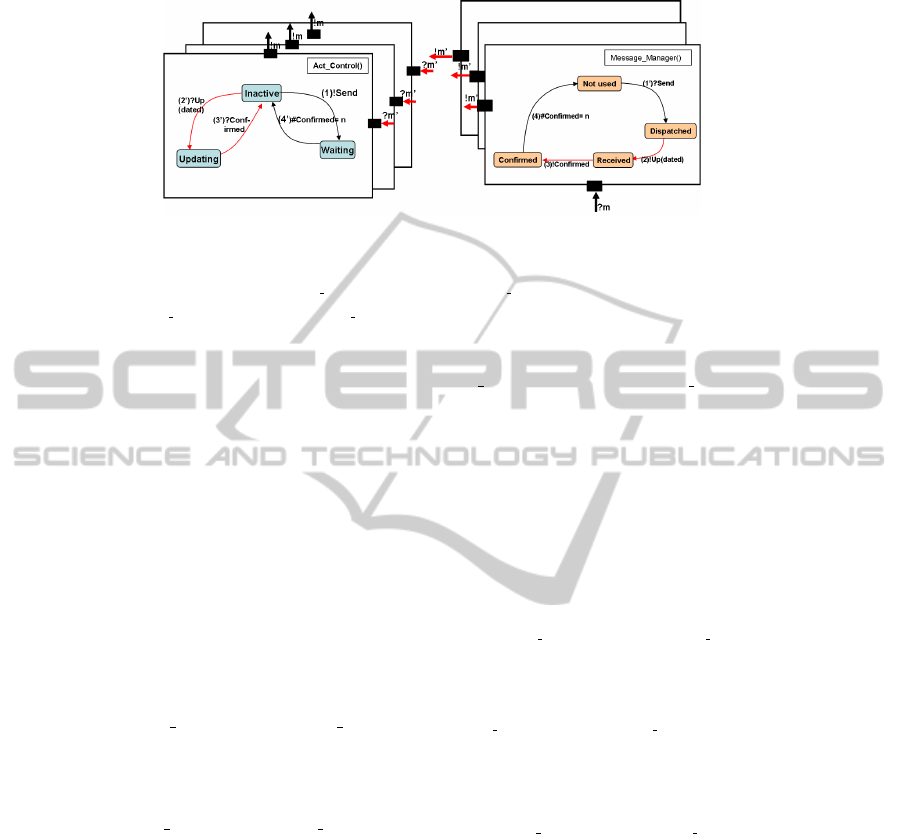
Fig.3. DBM Composite Structure Communications.
1. The input signals (Σ
Act Control
and Σ
Message M anager
) and the output signals
(Ω
Act Control
and Ω
Message Manager
) of both components are disjoint. In Figure
3 it can be seen how the encapsulation of the automata that only communicate
through dedicated input/output ports ?m and !m makes this condition always true.
2. The labelling sets of both components L(Act Control) and L(Message Manager)
are disjointed. This can also be easily verified since transition and state labels of
each automaton are only visible inside the capsule.
The main interest of Theorem 1 is to address the difficult problem of proving that
the satisfaction of a complex property of the system can be determined by the individual
verification of simpler properties of its components and the rules used to combine them.
In our case, the proposed adaptation of [23] Theorem has as its most important conse-
quence the fact that compositional verification of an SCS becomes reduced to proof the
reliability of a communication protocol between deterministic CSP+T processes with
interfaces and communication alphabets previously defined.
Finally, from (1) and (2), we can conclude that Act Control and Message Manager
system components are therefore “composable”,
Act ControlkM essage Manager |= φ
Act Control
∧ φ
Message Manager
(8)
and because of that we can affirm the compositional property of the entire system,
d
i
= Act ControlkM essage Manager and φ
d
i
= φ
Act Contr ol
∧ φ
Message Manager
,
(9)
And hence, the entire system’s model represented by each replicated DB manager d
i
satisfies the property φ
d
i
that represents every manager’s behaviour,
d
i
|= φ
d
i
. (10)
5 Conclusions
In this paper we have presented FCVA for compositional software verification from
independently verified individual components. MC was used to prove the correctness of
24

individual components and a CSP–based process calculus inspired formal language was
integrated in order to foster the composition of SCS, aided by concurrent composition
operators.
We have shown the value and practicality of our approach by means of the appli-
cation to a real–life project in the field of mobile communications, which has to meet
time critical requirements. The CSP+T specification of the system components at the
design phase can be verified against the CCTL specification of the individual system
component properties
References
1. A. M. Ben Amram, S. Genaim, and A. N. Masud. On the termination of integer loops. In In:
Viktor Kumcak and Andy Rybalchenko editors, Verification, Model–Checking and Abstract
Interpretation, Lecture Notes in Computer Science (to appear), Springer–Verlag, D, 2012.
2. A. Biere, A. Cimatti, E. M. Clarke, O. Strichman, and Y. Zhu. Bounded model–checking.
Advances in Computers, 58:117–148, 2003.
3. T. Bultan, J. Fischer, , and R. Gerber. Compositional verification by model checking for
counter–examples. In ISSTA ’96: Proc. of the 1996 ACM SIGSOFT International Sympo-
sium on Software Testing and Analysis, pages 224–238, New York, USA, 1996. ACM Press.
4. E. Clarke, D. Long, and K. McMillan. Compositional model checking. In Proc. of the Fourth
Annual Symposium on Logic in Computer Science, pages 353–362, Piscataway, USA, June
1989. IEEE Press.
5. J. M. Cobleigh, D. Giannakopoulou, and C. S. Pˇasˇareanu. Learning assumptions for compo-
sitional verification. LNCS, 2619(0):331–346, 2003.
6. O. Grumberg and D. E. Long. Model checking and modular verification. ACM TOPLAS,
16(3):843–871, 1994.
7. B. Lukoschus. Compositional Verification of Industrial Control Systems: Methods and Case
Studies. PhD thesis, Universitaet zu Kiel, Technischen Fakultaet der Christian-Albrechts,
July 2005.
8. W. Wong and M. Young. Compositionality reachability analysis using process algebra. In
Proc. of the Symposium on Testing, Analysis, and Verification: TAV4, pages 49–59, New
York, USA, 1991. ACM Press.
9. Luis E. Mendoza Morales and Manuel I. Capel. Automatic compositional verification of
business processes. Enterprise Information Systems, LNBIP, 24:479–490, 2009.
10. Luis Eduardo Mendoza, Manuel I. Capel, and Mar´ıa A. P´erez. Conceptual framework
for business processes compositional verification. Information & Software Technology,
54(2):149–161, 2012.
11. Y. Kesten, A. Klein, A. Pnueli, and G. Raanan. A perfecto verification: Combining model
checking with deductive analysis to verify real–life software. LNCS, 1708:173–194, 1999.
12. H. Giese, M. Tichy, S. Burmester, and S. Flake. Towards the compositional verification
of real–time UML designs. In ESEC/FSE–11: Proc. 9th European Software Engineering
Conference held jointly with 11th ACM SIGSOFT International Symposium on Foundations
of Software Engineering, pages 38–47, New York, USA, 2003. ACM Press.
13. G. Frehse, O. Stursberg, S. Engell, R. Huuck, and B. Lukoschus. Modular analysis of discrete
controllers for distributed hybrid systems. In The XV IFAC World Congress, pages 21–26,
Barcelona, Spain, 2002. IFAC.
14. C. de la Riva and J. Tuya. Automatic generation of assumptions for modular verification of
software specifications. Journal of Systems and Software, 79(9):1324–1340, 2006.
25

15. N. Moffat and M. Goldsmith. Assumption—commitment support for CSP model checking.
Journal of Automated Reasoning, 41(3-4):365–398, 2008.
16. H. Wehrheim and D. Wonisch. Compositional CSP traces refinement checking. Electronic
Notes in Theoretical Computer Science, 250(2):135–151, 2009.
17. B. Metzler, H. Wehrheim, and D. Wonisch. Decomposition for compositional verification.
In Proceedings of the 10th International Conference on Formal Methods and Software Engi-
neering, ICFEM ’08, pages 105–125, Heidelberg, Germany, 2008. Springer-Verlag.
18. C. A. R. Hoare. Communicating Sequential Processes. International Series in Computer
Science. Prentice–Hall International Ltd., Hertfordshire UK, 1985.
19. J. Zic. Time–constrained buffer specifications in CSP+T and Timed CSP. ACM TOPLAS,
16(6):1661–1674, 1994.
20. J. Ruf and T. Kropf. Symbolic model checking for a discrete clocked temporal logic with in-
tervals. In Proc. of the IFIP WG 10.5 International Conference on Correct Hardware Design
and Verification Methods, pages 146–163, 1997.
21. Kawtar Benghazi Akhlaki, Manuel I. Capel-Tu˜n´on, Juan Antonio Holgado Terriza, and Luis
E. Mendoza Morales. A methodological approach to the formal specification of real-time
systems by transformation of uml-rt design models. Science of Computer Programming,
65(1):41–56, 2007.
22. A. Rabinovich. On compositionality and its limitations. ACM TOCL, 8(1):1–26, 2007.
23. M. Abadi and L. Lamport. Conjoining specifications. ACM TOPLAS, 17(3):507–535, 1995.
24. K. Jansen. Coloured Petri Nets. Springer-Verlag Inc., New York, USA, 1997.
25. FormalSystemsEuropeLtd. Failures–Divergence Refinement – FDR2 User Manual. Formal
Systems Europe Ltd., Oxford, 2005.
26. S. A. Schneider. Concurrent and Real–Time Systems – The CSP Approach. John Wiley &
Sons, Ltd., 2000.
26
