
Development of a Wheelchair with a Lifting Function
Yoshikazu Mori
1
, Norikatsu Sakai
2
and Kaoru Katsumura
3
1
Department of Intelligent Systems Engineering, Ibaraki University, Nakanarusawa 4-12-1, Hitachi, 316-8511, Japan
2
SMC Corp., Akihabara UDX15F, 4-14-1, Sotokanda, Chiyoda-ku, 101-0021, Japan
3
Tamron Co., Ltd., 1385 Hasunuma, Minuma-ku, Saitama-city, Saitama 337-8556, Japan
Keywords: Medical and Welfare Assistance, Mechatronics, Design, Disabled Person, Care Lift, Transferring.
Abstract: A wheelchair with a lifting function is designed to assist a caregiver when transferring a wheelchair user not
only indoors but also outdoors. The target user is typically a severely disabled person with disabled upper
and lower limbs, and therefore needs the physical support when using a toilet or transferring from a bed to a
wheelchair and so forth. Both the wheelchair and the lift are driven by their respective motors. The user can
approach above the toilet stool or the bed from the rear because the large driving wheels are located in front
of the body and the seat can be folded. This wheelchair is allowed to travel on public roads because of the
mechanism of folding the frame for lifting. This paper presents the concept design and the experimental
results of a full-sized prototype wheelchair with the lifting function, which confirms the design
effectiveness.
1 INTRODUCTION
Persons with disabilities attributable to the lower
limbs are becoming increasingly numerous
worldwide. In Japan, they number about 3,480,000
(severely disabled persons were about 760,000) in
2006. Most of them use wheelchairs in daily life.
Representative nursing care in daily life entails
basing, evacuating, and feeding. Transfer when
basing, evacuating, and other processes causes back
pain to caregivers. Matsumoto et al. reported that
77% of caregivers and 64% of nurses have back pain
(Matsumoto and Kusunose, 1999). Consequently,
various devices and robots have been developed.
Molift Inc. developed the “Quick Raiser 2”, which
lifts a user with a linear actuator and supports the
standing-up and seating motions (Molift, 2012).
Sankai proposed some exoskeleton-type power-
assisted systems using electric motors and air
actuators (Satoh et al., 2009). Bostelman et al.
developed a robot system that a user himself wears
and enables him to use a toilet, a bed, and so forth
(Bostelman and Albus, 2007). A caregiver robot “RI-
MAN” developed at RIKEN is aimed at realizing
autonomous motion transfer (Onishi et al., 2007).
Some of those tools and robots are, however,
expensive and are limited for use in indoor
environments.
We take notice of a transfer tool that can be used
even when going away. Similar to some commercial
transfer products, “Komawari-san” is a simple tool
based on lever principles (HEARTS-EIKO, 2012).
These tools, however, are too large and heavy to
carry over long distances. “RODEM” is a new type
of electric wheelchair on which the user can ride
from the backside and which can run outdoors, but
the target is limited to mild patients (VEDA, 2012).
This paper presents a wheelchair with a lifting
function that is intended mainly for use by an
electric wheelchair user with disabled upper and
lower limbs. This equipment has good
maneuverability. Moreover, it can move over a step
because of the front driving wheels. It realizes easy
and safe transfer from/to a bed and a toilet stool by
virtue of the opposite wheel allocation of a usual
wheelchair. Furthermore, the mechanism of folding
the frame for lifting allows this wheelchair to travel
on public roads. We demonstrate its design
effectiveness through several indoor and outdoor
experiments.
2 CONCEPTUAL DESIGN
We assume a single caregiver for the use of this
wheelchair. It helps alleviate the burden of the
caregiver when a disabled person moves between the
wheelchair and toilet/bed easily and safely.
489
Mori Y., Sakai N. and Katsumura K..
Development of a Wheelchair with a Lifting Function.
DOI: 10.5220/0004114904890492
In Proceedings of the 9th International Conference on Informatics in Control, Automation and Robotics (ICINCO-2012), pages 489-492
ISBN: 978-989-8565-22-8
Copyright
c
2012 SCITEPRESS (Science and Technology Publications, Lda.)
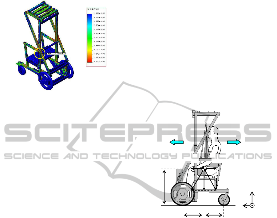
Figure 1: Analysis of the strength when lifting.
(1) The wheelchair has a lifting function. The lifting
mechanism comprises a lifting frame, a sling
seat, and a winch such as a conventional. The
winch is driven by an electric motor that a
caregiver operates using an up/down switch.
This winch is not back-drivable because a worm
gear and a worm wheel are used in it. Therefore,
this design is safe: the previous state remains
even if the power source is cut off. A toileting
sling is used for this equipment. Therefore the
user can wear it in a seated position and take off
underclothes in the lifting position easily.
(2) Large driving wheels are located in front of the
body, and the seat can be folded. Therefore, the
user can approach above a toilet stool and a bed
from the rear. As a result, this equipment can lift
a user easily and safely. Furthermore, this
location: front driving wheels are rigid and rear
wheels are casters, has good maneuverability
resembling that of a forklift truck.
The user can travel outdoors, even on public
roads, because a driving unit for an electric
wheelchair is used for this equipment and it has a
mechanism of folding the frame for lifting.
3 ANALYSES OF STRENGTH
AND STABILITY
The strength of the equipment is analyzed using
finite element method with COSMOSWorks, which
is add-in software of 3D-CAD software SolidWorks.
The conditions of the analysis are the following: The
user weight is 150 kg. Vertical loads are taken to the
lifting frame or the seat frame. Aluminum alloy
(A6063, yield stress = 145 N/mm
2
) is referred. The
following results were obtained through these
analyses:
(1) The maximum stress is 54.8 N/mm
2
at the lifting
frame when lifting. This value is under the yield
stress of the aluminum alloy (145 N/mm
2
).
(2) The maximum displacement is 4.00 mm at the
lifting frame when lifting.
(3) The safety ratio is 2.15 FOS when lifting. The
results are portrayed in Figure 1. Here, the
minimum value is shown in a circle.
Next, the equipment stability during transfer is
discussed. We discuss two cases because the user is
lifted vertically in a stationary state; then the user
moves to a target point in horizontal direction. We
analyze the former and latter cases respectively using
the stability margin and Zero moment point (ZMP).
z
x
y
2
Ma
1
Ma
z
1
1
x
2
x
Mg
2
a
Figure 2: Model for analysis of falling.
Figure 2 shows the model during expansion. Here,
1
x
and
2
x
respectively signify the distances between
the projected point of the center of gravity (COG)
and the positions of the rear casters and the front
wheels.
1
y
signifies the distance between COG and
the line that connects the front wheel and the rear
caster. Also,
1
z
denotes the height of COG from the
floor.
The calculated position of COG of the equipment
when carrying a subject (166 cm height, 65 kg
weight), considering the weights of the equipment
and the subject, is nearly at the top of his thigh (
1
z
=
651.8 mm), and
1
x
,
2
x
and
1
y
are 352.6 mm, 357.4
mm and 292.1 mm, respectively. Those values
respectively equal the backward, forward and
sideward stability margins. Here, the direction of the
rear casters is assumed to be in the front of each
rotation axis because the equipment goes backward
to a toilet stool and a bed (see Figure 2).
ICINCO 2012 - 9th International Conference on Informatics in Control, Automation and Robotics
490
Joystick
Hook
Pulleys
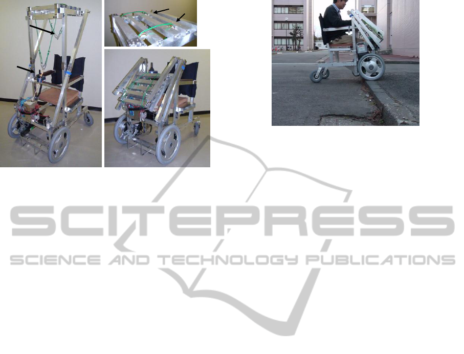
(a) when expanding (b) when folding
Figure 3: A full-sized prototype of a wheelchair with a
lifting function.
Next, we discuss stability during travel. The
safety acceleration against falling
i
a
(
i
=1, 2, 3) is
calculated as
1
zMaxMg
ii
(
i
=1, 2) and
(1)
131
zMayMg
,
(2)
where
M
represents the total mass of the user and
the equipment, and
g
signifies acceleration of
gravity. The position of the rear caster to the rotation
axis changes according to the traveling direction,
1
x
=472.6 mm,
2
x
=357.4 mm and
1
y
=295.9 mm
when traveling forward, whereas
1
x
=352.6 mm,
2
x
=357.4 mm, and
1
y
=292.1 mm when traveling
backward. Therefore, the safety accelerations against
falling are calculated:
1
a
=7.11 m/s
2
and
3
a
=4.46
m/s
2
when traveling forward, whereas
2
a
=5.31 m/s
2
and
3
a
=4.41 m/s
2
when traveling backward.
4 EXPERIMENTS
We address two basic operations: traveling and
transfer experiments. The subject was a man (166 cm,
65 kg) with no leg motion impairment.
Figure 3 shows the appearance of the hardware.
The size in expanding is 100(L)
68(W)
162(H)
cm, and that in folding is 100(L)
68(W)
105(H)
cm, excluding the height of the cushion, and the
weight is 47 kg. Road Traffic Law in Japan does not
allow a wheelchair which size is over
120(L)
70(W)
109(H) cm to travel on public
roads, however, the size in folding is within the
limited size.
Figure 4: Snapshots of the traveling experiments when
going up a step.
The winch gearbox of the lifting mechanism that
comprises a DC motor (250 W, RE75; Maxon Corp.),
a winding rod, spur gears, a worm gear and a worm
wheel. The worm gear and the worm wheel make this
winch back-drivable, so the user is safe even if the
power source is cut off. The lifting cord connected to
the winding rod is split into two parts and passes on
the pulleys that are attached to the lifting frame. A
hook is attached to each end of the lifting cord, and
two hooks connect the lifting cord to the sling seat.
Output torque of 44.2 Nm is necessary to lift a 100
kg load. The maximum torque of the winch (its
reduction ratio = 1/257) is 95.6 Nm (transmission
efficiencies of the spur gears and worm gears =
0.98% and 0.5%, respectively). The maximum lifting
rate is designed to be 10 mm/s. We used a V55 CPU
board (16 MHz; Japan System Design Corp.) and
two batteries (WP2.6-12; Kung Long Batteries
Industrial Co., Ltd.) for the lifting mechanism, which
was controlled based on PD control theory. The
sampling time was 20 ms.
This equipment has large driving wheels in the
front that are the parts of a commercial electric
driving unit for a wheelchair (Joy Unit, 8.2 km/1-
charge, forward: 2.5 km/h and 4.5 km/h, backward:
2.0 km/h, approximately 17 kg including a battery,
YAMAHA Corp.).
4.1 Traveling Experiments
First, we confirmed the motions of traveling forward
and backward and for turning in indoor environments.
The user operated the equipment using a joystick in
the same way as that used for a commercial electric
wheelchair. Consequently, we noted that the user was
not required to lean the joystick when turning
because the driving wheels were arranged in front of
the body.
Development of a Wheelchair with a Lifting Function
491
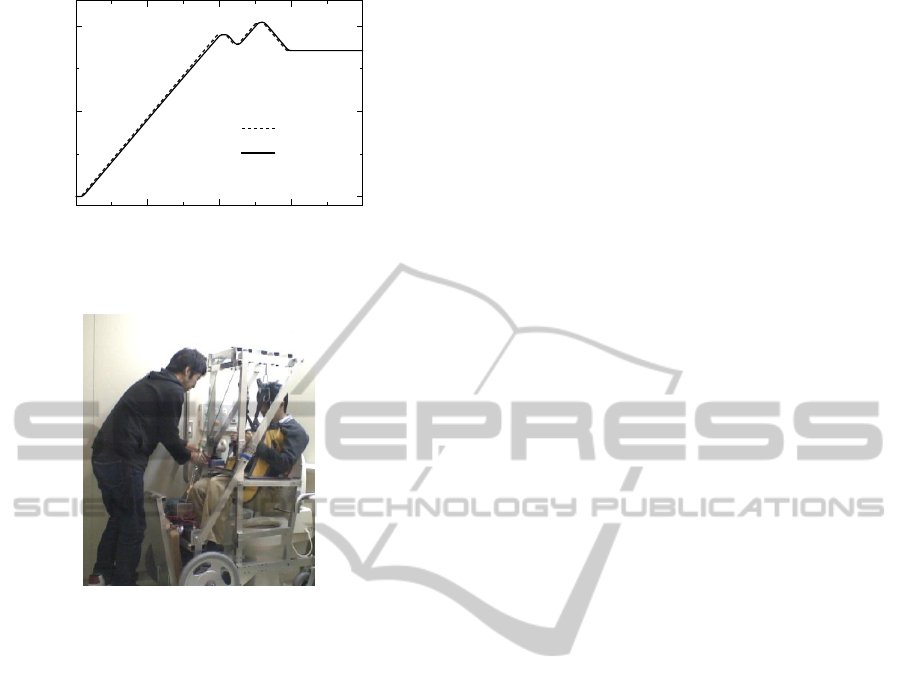
0 10 20 30 40
0
10
20
Time [s]
Lifting height [cm]
Target
Actual
Figure 5: Time response of the lifting height when lifting.
Figure 6: Snapshots when transferring to a toilet.
Figure 4 shows results of the outdoor examination
when ascending a 5 cm step. It was possible to go
up/down the step because of the front driving wheels,
although it is difficult for a conventional electric
wheelchair to go up about 3 cm step. We also
confirmed that the equipment had sufficient ability to
travel on a field.
4.2 Transfer Experiment
We examined the lifting motions. The results are
presented in Figure 5. The lifting velocity was
calculated from the difference of the lifting height
measured by an encoder installed in the winch. The
motion is operated manually using an up/down
switch. The lifting mechanism was controlled with
trapezoidal speed profile, with target acceleration of
2.5 cm/s
2
and target maximum velocity of 1 cm/s.
The directing maximum lifting velocity was about
one-third of that of commercial lifts considering the
clearance about 20 cm from the lifting frame to the
head of the user. Accuracy of better than
approximately 0.3 cm for the lifting height and
approximately 0.04 cm/s for the lifting velocity at 25
s was obtained. The error of the lifting height was
approximately 0.01 cm after 30 s. Those results
show that this winch can follow the target trajectory.
The trapezoidal speed controller realized smooth
up/down motions, and the subject was lifted stably.
Figure 6 depicts the experimentally obtained
result obtained for transfer to a toilet stool in a toilet
for physically handicapped persons. The toilet stool
height was 45.6 cm. The toilet stool width was about
20 cm, although the minimum width between the
rear frames of the equipment is 37 cm. We
confirmed that the subject was able to approach
above the toilet stool from the rear.
5 CONCLUSIONS
We proposed a novel wheelchair with a lifting
function for an electric wheelchair user with disabled
upper and lower limbs. This equipment facilitates
easy and safe transfer from/to a bed and a toilet stool
by virtue of the opposite allocation of wheels from
that for a usual wheelchair. Furthermore, the
mechanism of frame folding for lifting allows this
wheelchair to be used on public roads. Results show
that this equipment had good maneuverability like a
forklift truck. We also demonstrated that the
equipment had sufficient ability of moving up/down
a 5 cm step and of traveling on a field. It can be used
in an actual toilet. In future works, we plan to
improve this system for better practical use,
mechanical strength, and design.
REFERENCES
Bostelman, R. and Albus, J., 2007, A Multipurpose
Robotic Wheelchair and Rehabilitation Device for the
Home, Proc. of the IEEE/RSJ Int. Conf. on Intelligent
Robots and Systems, pp. 3348-3353.
HEARTS-EIKO Corp., 2012, Komawari-san, http://www.
hearts-eiko.co.jp/koma/komawari.html.
Matsumoto, T. and Kusunose, K., 1999. The status quo
and problem for occupational low back pain, Journal
of Clinical Rehabilitation, Vol. 8, No. 2, pp. 115-118.
Molift AS - an Etac company, 2012, molift, http://www.
molift.com/en/.
Onishi, M., Luo, Z., et al., 2007, Generation of Human
Care Behaviors by Human-Interactive Robot RI-MAN,
Proc. of the IEEE Int. Conf. on Robotics and
Automation, pp. 3128-3129.
Satoh, H., Kawabata, T. and Sankai, Y., 2009. Bathing
care assistance with robot suit HAL, Proc. of the IEEE
Int. Conf. on Robotics and Biomimetics, pp. 498-503.
VEDA International Robot R&D Center Incorporated
Association, 2012, http://www.veda-robot.com/.
ICINCO 2012 - 9th International Conference on Informatics in Control, Automation and Robotics
492
