
Experience-based Fuzzy Control of an Anthropomimetic Robot
Veljko Potkonjak
1
, Nenad Bascarevic
1
, Predrag Milosavljevic
1
, Kosta Jovanovic
1
and Owen Holland
2
1
Faculty of Electrical Engineering, University of Belgrade, Bulevar ralja Aleksandra 73, 11000 Belgrade, Serbia
2
School of Informatics, University of Sussex, Brighton BN1 9 QJ, Falmer, U.K.
Keywords: Knowledge Base Control, Fuzzy Control, Machine Learning, Robot Arms, Bio-inspired Robot.
Abstract: This paper aims to present a novel experience-based solution for a black-box control problem, applied to an
anthropomimetic robot. The control method is tested on a point to point control problem of a multi-jointed
robot arm. The model characteristics – dynamics, kinematics, and control parameters – are considered as
unspecified, and therefore we deal with a machine learning approach that follows the cybernetic concept of
black-box. The only available data of the system are those obtained from measuring inputs and outputs. The
control algorithm involves two levels: feedforward and feedback. The main focus is, however, on feedback
level where the algorithm for experience-based estimation of kinematic coefficients is combined with fuzzy
logic control in order to relate the control inputs with the robot arm motion in the global frame.
1 INTRODUCTION
Contemporary humanoid robots are constructed in
order to replicate humans just by copying the outer
form, while keeping the internal classical machine
structure. If, however, one intended to replicate the
human internal mechanics, he would face a
situation: complex multi-degree-of-freedom joints,
muscles crossing over several rotation axes and
working in an antagonistic mode, presence of
mechanical compliance, etc. Such systems can no
more be modelled and controlled in a classical
analytical way – a biologically-inspired approach is
needed (Potkonjak et al., 2010).
Holland and Knight, 2006 have proposed a new
expression - anthropomimetics. It concerns a new
principle in robot construction (Fig. 1), mimicking
the human body, skeleton and muscle system. The
goal is to attain a high level of performances (e.g.
maneuverability) analogous to human paragon. The
idea of this paper is based on the work done within
the project ECCEROBOT (European 7th Framework
Program, project “Embodied Cognition in a
Compliantly Engineered Robot”).
By combining the experience-based approach
with fuzzy logic, this paper aims to solve the point-
to-point control problem in the absolute frame, i.e.
find a way to control the anthropomimetic robot in
reaching a prescribed hand tip position.
The outline of this paper is as follows. A short
overview of most similar projects and related topics
is presented in Section 2. Section 3 shows an
empirical approach to feedforward (FF) control. The
influence of each control input on the hand tip
motion in the global frame is evaluated in Section 4.
By implementing the fuzzy logic algorithm in
Section 5 we form the final control as FF+feedback
(FB) for the anthropomimetic robot arm. Efficiency
of our control algorithm is shown in Section 6.
(a) (b)
Figure 1: (a): ECCEROBOT test rig. (b): The latest
prototype of the ECCEROBOT.
2 RELATED WORKS
The posed problem can be considered from different
points of view, as black-box modeling or
identification of nonlinear systems.
389
Potkonjak V., Bascarevic N., Milosavljevic P., Jovanovic K. and Holland O..
Experience-based Fuzzy Control of an Anthropomimetic Robot.
DOI: 10.5220/0004117503890394
In Proceedings of the 4th International Joint Conference on Computational Intelligence (FCTA-2012), pages 389-394
ISBN: 978-989-8565-33-4
Copyright
c
2012 SCITEPRESS (Science and Technology Publications, Lda.)

Rivals and Personnaz, 1995 showed that there
are advantages in using nonlinear state-space
models, including a larger class of nonlinear
dynamical models. Several examples of nonlinear
black-box model structures and approximation
issues are proposed by Ljung, 2001. Relationships
between fuzzy models, neural networks and classical
non-parametric models are discussed. Van Mulders
et al., 2009 introduced two nonlinear optimization
methods for the identification of nonlinear black box
systems. Each method relies on estimation of the
parameters of a polynomial nonlinear state-space
model by means of a nonlinear least-squares
optimization. Gonzalez-Olvera et al., 2009 presented
a black-box modelling of two degrees of freedom
manipulator. Recurrent neural networks with output
feedback are used to solve the visual servoing
problem.
Another possible solution for the black-box
control can be determined by applying machine
learning or predictive control algorithms.
Researchers in the field of robotics, Chhabra and
Jacobs, 2008 introduce a new learning model for
simulated two-joint arm motor control referred to as
the Greedy Additive Regression (GAR) model. The
model maintains a base of control sequences (i.e.,
motor synergies) and it is presented for learning the
coefficients of a linear combination of sequences.
Stulp et al., 2009 presented both, human data and
experience-based learning, in order to determine if
the end-effector can be brought into a position where
the object can be grasped, regardless of the path.
Haruno et al., 2001 proposed a new modular
architecture, the modular selection and identification
for control (MOSAIC) model, for motor learning
and control based on multiple pairs of forward
(predictor) and inverse models.
3 FEEDFORWARD LEVEL
3.1 Biologically Inspired Control
Potkonjak et al., 2012 presented the control of
antagonistic drives based on a biologically inspired
puller-and-follower concept for a single joint
system. The pattern of the EMG activity in elbow
flexors when a slow linear flexion movement is
produced against small constant load is analysed by
Tal’nov et al., 1999. After reaching the final value of
the joint angle, the burst in the agonist (AG) EMG
intensity slowly drops to a steady-state level. In
order to provide fine tuning of joint position, AG
activation is followed by burst in antagonist (ANT).
We apply the same logic to control the joints in the
robot. Namely, the input voltage fed into the
actuators must generate similar commands to
muscles, followed by the appropriate activation of
ANT. Fig. 2 demonstrates the input voltage of the
controlled joint and its position. It allows to
distinguish two input voltage components in both
AG and ANT: the control signal burst mainly
responsible for the joint motion; and the silent
period that keeps the reached steady state position.
The ratio between the maximum values of the AG
and ANT inputs as well as the ratio between their
burst time duration are constant for a particular joint.
Therefore, in order to move the joint to the required
position we should change appropriately the AG
maximum value and its burst time duration, while
the ANT value and its burst time duration are
proportionally modified. Namely, it is assumed that
antagonist activation would always make
proportional contribution to joint motion, compared
to agonist contribution. The joints are controlled by
voltage inputs presented in Fig. 2.
Figure 2: Top: Agonist and antagonist input voltage
control. Bottom: The obtained elbow angle during
appropriate control.
3.2 Experience Acquisition in
Multi-jointed System
The approach used in controlling a single-joint is
now generalized to the multi-jointed robot arm. In
examples, a fixed-base arm with seven single-
degree-of-freedom joints moved by antagonistically
coupled drives is considered. The experience
acquiring means the set of motion experiments
performed from a set of initial hand-tip positions
which define the initial region, and ending in a
region of final positions. Figure 3 shows the initial
and the final region. When performing a motion
experiment, the joints are controlled by heuristically
determined control voltages which follow the pattern
0 0.5 1 1.5 2 2.5 3
0
1
2
3
4
5
Input voltage
0 0.5 1 1.5 2 2.5 3
5
10
15
20
25
30
time [s]
Elbow angle
Agonist voltage
Antagonist voltage
IJCCI2012-InternationalJointConferenceonComputationalIntelligence
390

presented in Fig. 2. The used pointing example does
not specify the path, only the end point.
Figure 3: Recorded initial and final positions of robot hand
tip.
The positions shown in Fig. 3, the initial and the
final sets, together with the controls applied in these
experiments are recorded and represent the system
experience, the experience base. The region of initial
positions is a sphere with the radius of 0.1, while
final region is in the sphere with the radius of
0.05. In case of a larger sphere, we have to spend
more time on experience acquisition if we intend to
keep the same distances within the grid, or we may
create a grid with larger distances which however
would require a more complex interpolation
procedure.
Created in the above described way, the
experience base relates the initial positions and the
input voltages, on one side, with the reached points
(output) on the other. Knowledge acquiring, the
training, means filling in the base. In our example,
for each initial position there are 90130 final
positions in the final sphere. The distances in the
initial grid are between 2.5 and3.5. The
relevant distance in the final set of positions
concerns the final points that resulted from the same
initial point: the distances are from 2 to2.5.
3.3 Feedforward Exploitation in
Multi-jointed System
In the exploitation stage the robot is required to
reach a target point (hand-tip position
) that has
not been previously reached in training, starting
from a position (
) that has not been previously
used. In this phase, the experience base is used to
derive the appropriate input control pattern. Here, a
linear interpolation scheme was applied to compute
the control from a set of closest neighbors found in
the base. The FF motor control represents as a linear
combination of these neighboring control sequences
(Chhabra and Jacobs, 2008).
The interpolation and the calculation of the FF
control are done before the robot moves, i.e. off-line.
Since any interpolation gives the approximate
solution, the obtained control would drive the robot
to a vicinity of the target point; the deviation being
dependant on the competency of the knowledge base
and the interpolation method; hence the closest
neighbours would be used for FF interpolation.
Therefore, the algorithm starts with the sequential
search for the closest four initial positions around
,
from the initial set. Also, the four final positions
around
, from the final set, as well as the control
inputs are chosen for the linear interpolation
algorithm. The positions
and
must be inside of
polyhedral defined by neighbours from the initial
and the final sphere, respectively. Namely, after
acquiring stage, the model shows generalization to
novel tasks whose dynamics lie within the
polyhedral of already learned dynamics (Haruno et
al., 2001). The total control input for each motor is
the summation of the sequences from experience
base using the coefficients, to weight the
contributions. Numerous experiments of FF
interpolation, in our case of the ECCEROBOT, have
shown that the distance between the position reached
by FF and the target position
in global frame does
not exceed 6. The required precision of the
robot hand tip is set to 1 in each axis. FF control
is not sufficient to drive the hand tip into satisfactory
final position. To achieve this requirement we need
to extend the control by adding feedback for fine
tuning. Therefore, at the moment when the tip is at
6 distance from the final point, the feedback
component is added.
4 FUZZY LOGIC FEEDBACK
CONTROL
We shortly remind of the goal – solving the point-to-
point control problem in the global frame, relying
only on experience. The fuzzy logic (Zadeh, 1965) is
chosen to cope with this complex problem. A fuzzy
controller is implemented.
In the proposed fuzzy controller we use two
input variables (position error and derivative of
position error) and one output variable (voltage) for
each axis. The membership functions for inputs and
output are shown in Fig. 4.
As shown in Fig. 4, fuzzy membership functions
-0.1
0
0.1
0.2
0.3
0.4
0.5
0.6
-0.4
-0.2
0
-0.5
-0.4
-0.3
-0.2
-0.1
0
0.1
Z axis
INITIAL
POSITIONS
FINAL
POSITIONS
Experience-basedFuzzyControlofanAnthropomimeticRobot
391

comprise a range of values and can actually overlap.
Triangular shapes have been adopted for the fuzzy
subsets. Both input variable ranges (
,
) were
founded experimentally and the inputs do not exceed
defined values. The maximum feedforward position
error is extended to a 10mm in a case of the lower
base resolution. The “diff_error” input (and “error”
as well) is calculated every 0.001s (sampling time),
so derivative of the error has low values and
rescaling was required to obtain reasonable range of
inputs. The following five and seven fuzzy levels are
chosen for the control inputs of the fuzzy controller
in the fuzzification process. These numbers of sets
are established as optimal values for our system. The
final region of interests for “error” variable is
between [-1mm, 1mm], so the first fuzzy set (NOE)
has to be in that range, the second and the third set
(SNE and SPE) have to overlap with the first set and
have to be narrow if we want to control the error
near the zero value. The fourth and the fifth set (NE
and PE) cover a wider range around 5mm value and
the sixth and the seventh set (VNE and VPE) cover
more than 6mm values in a case of greater error.
These seven sets are also required for smooth error
change definition due to time. Numerous simulations
showed more satisfactory results if the sets do not
overlap at 0.5 degree. The number of sets depends
on the (input range)/(final region range) ratio and the
desired time response of the system. Analogues
procedure is applied to “diff_error” sets.
Figure 4: Membership functions for position error,
derivative of position error and voltage.
Seven sets of membership functions are defined
for the output variable “voltage”. We want to avoid
rough fluctuations of the voltage during changeable
position error and thus seven sets, including
overlapping between two consecutive sets, are
implemented.
If-then rule base is shown in Table 1. All
possible rule combinations of fuzzy inputs and their
results as outputs are presented in that table. The
used fuzzy operator is AND.
The derivation of the
fuzzy control rules is heuristic in nature and based
on the following theoretical criteria presented in
Table 1. Finally, for our purposes the centroid
defuzzification method is used.
Table 1: If-then rules.
ERROR
DERIVATIVE OF ERROR
AND
DNE SDNE DZE SDPE DPE
VNE VNV VNV VNV VNV VNV
NE NV NV SNV SNV NOV
SNE NV SNV SNV NOV SPV
NOE NV SNV NOV SPV PV
SPE SNV NOV SPV PV PV
PE NOV SPV SPV PV PV
VPE VPV VPV VPV VPV VPV
The meanings of the acronyms from Table 1 are
shown in Table 2.
Table 2: The meanings of the acronym from the Table 1.
ERROR DIFF_ERROR
VNE-very_negative_error
NE – negative_error
SNE – Snegative_error
NOE – no_error
SPE – Spositive_error
PE – positive_error
VPE – very_positive_error
DNE – diff_negative_error
SDNE–Sdiff_negative_error
DZE – diff_zero_error
SDPE– Sdiff_positive_error
DPE – diff_positive_error
VOLTAGE
VNV – very_negative_voltage NV – negative_voltage
SNV – Snegative_voltage NOV – no_voltage
SPV – Spositive_voltage PV – positive_voltage
VPV – very_positive_voltage
5 KINEMATIC COEFFICIENTS
The fuzzy logic was implemented and now we
dispose with the control signals of our process.
There are 2n (in our case n=7) control inputs and
only three outputs (x, y and z position), so that a
question is posed: How to determine the influence of
each control input on the hand tip motion in the
global frame?
Although this system has fourteen inputs, the
feedback phase uses only seven independent inputs,
the pullers, to control the hand tip positioning. The
other seven result from the puller-follower concept
(Potkonjak et al., 2012).
-0.01 -0.005 0 0.005 0.01
0
0.2
0.4
0.6
0.8
1
ERROR (INPUT)
VNE
VPE
NE
NOE
PE
SNE
SPE
Degree of member s hi p
-1 -0.5 0 0.5 1
0
0.2
0.4
0.6
0.8
1
DIFF__ERROR (INPUT)
Degree of member shi p
DNE
DZE DPE
SDNE
SDPE
-2 -1.5 -1 -0.5 0 0.5 1 1.5 2
0
0.2
0.4
0.6
0.8
1
VOLTAGE (OUTPUT)
VNV
NOV
VPV
NV
PV
SNV SPV
Degree of member s hi p
IJCCI2012-InternationalJointConferenceonComputationalIntelligence
392

Kinematic coefficients are defined as parameters
which describe the relation between control inputs
and the axes of the global frame. For each joint
(controlled by two inputs), three normalized
coefficients
,
,
are assigned, for x, y and
z axis, respectively.
Suppose that pure feedforward brings the hand
tip to point
(
,
,
). Coordinates of the
points from the narrow environment (neighbours of
) are denoted as (
,
,
), 1,2,…,(-
neighbour number). This chapter presents only the
algorithm for the x axis – the analogues procedure is
applied for y and z axes. The first calculated
parameter is
(1)
which defines normalized distance (between
feedforward and the neighbouring position) in
comparison to and distance for the current
neighbour
. Next calculated parameter is about
joint angle position in the local frame:
;
…
(2)
which determines normalized deviations between
joint positions (
;jointnumber) reached by
FF, and joint positions (
) of the neighbour.
Parameter
is used to normalize the joint
difference between all seven joints for the chosen
neighbour in the joint space. Now, the normalized
distance along axis between
and each
neighbour position
is evaluated. Equation (3)
estimates coefficients (
used to compare the
distances of each neighbour from
:
⋯
(3)
The required coefficients (
,
,
) have been
estimated. The influence of each coefficient should
be treated equally and therefore a product of these
parameters is formulated as a connection:
(4)
Equation (4) represents the influence of a particular
joint along x direction. The proper form which is
used as the final kinematic coefficient is
(5)
Finally, the influence of each joint on each axis
direction is calculated and can be used in final form.
The final equation for the control input during
feedback phase is
,
(6)
The variable
is a static voltage of i – joint
required to keep the joint in the prescribed position
during steady state. For the target position the static
voltage is estimated using feedforward algorithm
(see Section 3.3). The signs in (6) are chosen
experimentally using experience base. They
represent the situation when the control input is
increased, in which direction (positive “” or
negative “”) the hand tip moves to (for each axis).
6 SIMULATION RESULTS
Control was verified by simulation. The theory
developed above is applied to the simulator of the
robot arm driven by antagonistically coupled drives.
Figure 5: Hand tip position in global frame during
feedforward and feedback control.
Figs. 5 and 6 depict the example where the
feedforward makes the error of 5mm in z axis
direction. The whole motion of the robot arm
lasts5,5. During first 3 feedforward control is
applied in order to drive the robot arm tip from
initial position
to position
. In the next2,5 the
system is controlled by FF and FB. In spite of
oscillations caused by fuzzy controller the final hand
tip position finally comes into prescribed region,
1mm around the reference position
(Fig. 5).
Figure 6 shows FF and FB control signals.
3 3.5 4 4.5 5 5.5
0.529
0.53
0.531
0.532
X position [m]
3 3.5 4 4.5 5 5.5
-0.222
-0.22
-0.218
Y position [m
]
3 3.5 4 4.5 5 5.5
-2
0
2
4
6
x 10
-3
Time [s]
Z position [m]
Hand tip position along X,Y and Z axis
Reference position in global frame
Experience-basedFuzzyControlofanAnthropomimeticRobot
393
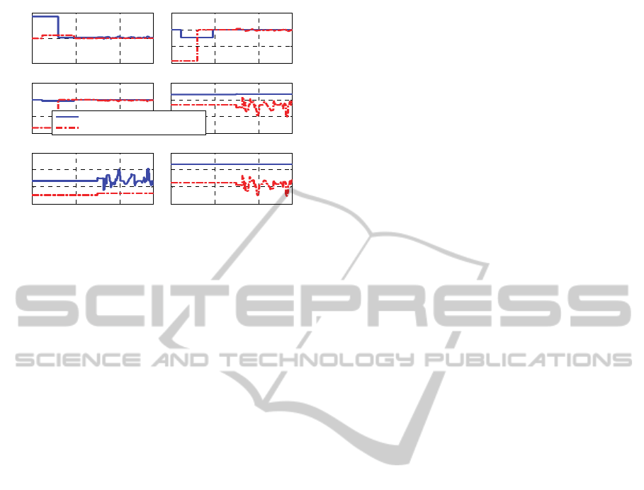
Figure 6: The feedforward and feedback control of the
most representative joints in the system.
7 CONCLUSIONS
The core of this paper was the implementation of
fuzzy controller along with estimation of kinematic
coefficients to formulate the feedback for a robotic
arm with antagonistically coupled compliant drives.
Since the suggested control algorithm relies on
the experience and fuzzy logic, it is expected to be
applicable to a wider class of robots. The only
modification would be different training data –
experience base should be customized for the
specific robot skills. Since the experience acquiring
stage in feedforward phase is time consuming,
further research can explore solution to speed up this
process. As our control depends on base resolution,
the future work would consider developing of more
sophisticated method to increase precision of the
control algorithm (e.g. to make more complex fuzzy
engine).
ACKNOWLEDGEMENTS
The research leading to these results has received
funding from the European Community's Seventh
Framework Programme FP7/2007-2013 - Challenge
2- Cognitive Systems, Interaction, Robotics - under
grant agreement no. 231864 - ECCEROBOT; and
partly by the Serbian Ministry of Science and
Technological Development under contracts 35003
and 44008.
REFERENCES
Chhabra, M., Jacobs, A., 2008. Learning to combine
motor primitives via greedy additive regression. The
Journal of Machine Learning Research. vol. 9. pp.
1535-1558.
Gonzalez-Olvera, M., Rodriguez-Morales, A., Tang, Y.,
2009. Black-box modeling of a 2-dof manipulator in
the image plane using recurrent neurofuzzy networks.
In Proc. of the IEEE Int. Conf. on Decision and
Control, pp. 8440-8445.
Haruno, M., Wolpert, D., Kawato, M., 2001. MOSAIC
model for sensorimotor learning and control. Neural
Computation. vol. 13. pp. 2201 – 2220.
Holland, O., Knight, R., 2006. The anthropomimetic
principle. In Proc. of The Symposium on Biologically
Inspired Robotics edited by J. Burn and M. Wilson.
Ljung, L., 2001. Black-box models from input-output
measurements. Proceedings of the 18th IEEE
Instrumentation and Measurement Technology
Conference. vol.1. pp. 138 - 146.
Potkonjak, V., Svetozarevic, B., Jovanovic, K., Holland,
O., 2010. Biologically inspired control of a compliant
anthropomimetic robot. In Proc. of the IASTED Int.
Conf. on Robotics and Applications. pp. 182 – 189.
Potkonjak, V., Svetozarevic, B., Jovanovic, K., Holland,
O., 2012. The puller-follower control of compliant and
noncompliant antagonistic tendon drives in robotic
system, International Journal of Advanced Robotic
Systems, vol. 8, pp 143-155.
Rivals, I., Personnaz, L., 1996. Black-box modeling with
state-space neural networks. Neural Adaptive Control
Technology. vol. 15. pp. 237-264.
Stulp, F., Fedrizzi, A., Zacharias, F., Tenorth, M.,
Bandouch, J., Beetz, M., 2009. Combining analysis,
imitation, and experience-based learning to acquire a
concept of reachability in robot mobile manipulation.
In Proc. of the IEEE Int. Conf. on Humanoid Robotics.
pp. 161-167.
Tal’nov, A., Serenko, S., Strafun, S., Kostyukov, A., 1999.
Analysis of the electromyographic activity of human
elbow joint muscles during slow linear flexion
movements in isotorque conditions. Neuroscience. vol.
90. pp. 1123-1136.
Van Mulders, A., Schoukens, J., Volckaert, M., Diehl, M.,
2010. Two nonlinear optimization methods for black
box identification compared. Automatica. vol. 46. pp.
1675–1681.
Zadeh, L., 1965. Fuzzy sets. Information and Control. vol.
8, pp. 338–353.
0 2 4
-5
0
5
right shoulder X joint
0 2 4
-10
-5
0
5
right shoulder Y joint
0 2 4
-10
-5
0
5
right elbow Y joint
Control inputs [V]
0 2 4
-1
-0.5
0
0.5
right elbow Z joint
0 2 4
-1
-0.5
0
0.5
right wrist Y joint
0 2 4
-0.5
0
0.5
1
right wrist X joint
Time [s]
Agonist control signal
Antagonist control signal
IJCCI2012-InternationalJointConferenceonComputationalIntelligence
394
