
CPN based Data Integrity Evaluation for Cloud Transactions
Yoshiyuki Shinkawa
Department of Media Informatics, Faculties of Science and Technology, Ryukoku University
1-5 Seta Oe-cho Yokotani, Otsu, Shiga, Japan
Keywords:
Colored Petri Nets, Cloud Computing, Transaction Processing, Data Integrity.
Abstract:
Cloud computing environments, especially the PaaS environments, are one of the most promising platforms
for high capacity and low cost transaction processing. However, today’s PaaS environments provide us with
limited capability for data integrity in database and transaction processing, compared with traditional transac-
tion management systems. Therefore, we need to evaluate whether the cloud environment currently considered
provides enough capability for our data integrity requirements. This paper presents a Colored Petri Net (CPN)
based approach to modeling and evaluating generalized transaction systems including cloud environments.
The evaluation is performed based on the given constraints on database records expressed in the form of pred-
icate logic formulae, and examined by CPN/ML codes implemented as the guard functions of the transitions
for integrity verification.
1 INTRODUCTION
Transactional integrity is one of the most critical and
challenging issues in cloud computing, since today’s
cloud environments, especially the PaaS (Platform as
a Service) environments, e.g. Google App Engine
(GAE) (Sanderson, 2009) or Amazon Elastic Com-
pute Cloud (EC2) (Vliet and Paganelli, 2011), de-
grade the capability of data integrity in exchange for
implementing highly scalable, distributed, and vir-
tualized platforms. The data integrity in traditional
transaction processing relies on the ACID
1
property
of each transaction, which is implemented as a major
functionality of every transaction management sys-
tem (Gray and Reuter, 1993).
Unlike these management systems, cloud environ-
ments provide us with more simplified mechanism for
data integrity, which is often referred to as BASE
2
property in contrast with ACID (Pritchett, 2008). One
of the most distinctive characteristics of BASE trans-
actions is that they are not totally isolated for preserv-
ing data integrity, and therefore the “C” (Consistency)
of the ACID property cannot be assured in BASE en-
vironments, and consequently the data integrity might
be broken. Due to this incomplete integrity assurance,
mission critical applications have been thought not to
1
Atomicity, Consistency, Isolation, and Durability.
2
Basically Available, Soft-State, and Eventual Consis-
tency.
be suitable to cloud computing environments.
However, for the evolution of cloud computing,
these applications are one of the critical success fac-
tors, since there are huge number of them are running
in the form of transactions. In order to deploy these
applications over cloud environments, we first have
to reveal their transactional behavior in the environ-
ments, along with the impact analysis to data integrity.
In order to deal with a variety of cloud environ-
ments including emerging ones, it seems a good prac-
tice to build a platform independent framework for
evaluating data integrity. In this framework, transac-
tion systems must be formalized for generalization.
Among numerous formalization tools, Colored Petri
Net (CPN) (Jensen and Kristensen, 2009)is one of the
most appropriate tools for this evaluation, since it can
express dynamic systems from both behavioral and
functional viewpoints simultaneously, along with the
simulation capability (Martin et al., 2004).
This paper presents a CPN based formal approach
to modeling and evaluating the transactional behavior
of database applications in cloud environments. The
paper is organized as follows. In section 2, we intro-
duce the basic concepts of “data integrity” from sev-
eral viewpoints. Section 3 presents CPN based mod-
eling techniques for the transactional behavior from
platform independent viewpoints. Section 4 discusses
how the CPN based models are evaluated for the con-
sistency.
267
Shinkawa Y..
CPN based Data Integrity Evaluation for Cloud Transactions.
DOI: 10.5220/0004120702670272
In Proceedings of the 7th International Conference on Software Paradigm Trends (ICSOFT-2012), pages 267-272
ISBN: 978-989-8565-19-8
Copyright
c
2012 SCITEPRESS (Science and Technology Publications, Lda.)

2 DATA INTEGRITY FROM
APPLICATION VIEWPOINTS
Data integrity is one of the most important issues in
software and system design relating to database and
transaction processing. However, the concept of “in-
tegrity” has many facets, and we need to discuss it
from different several viewpoints. The typical aspects
that the concept shows are “physical”, “logical”, “ap-
plication”, “system”, and so on. Various database or
transaction management systems provide us with so-
phisticated mechanism for the data integrity, in corpo-
ration with the operating systems and hardware con-
trollers, under which they are running.
In spite of these mechanisms, each application is
still responsible for the data integrity from its own
application viewpoints. Several relational database
management systems provide us with a few func-
tionality for this kind of data integrity, which in-
cludes “foreign key”, “referential integrity”, “do-
main”, “trigger”, and “stored procedure”.
In order to utilize this functionality properly, we
first have to define the application data integrity rig-
orously. However, the data integrity from application
viewpoints depends too much on individual applica-
tions, and consequently it seems difficult to generalize
and formalize it. In this section, we introduce a pred-
icate logic based generalization and formalization of
the data integrity. For the generalization, we define
data integrity as a set of constraints on the databases
to be used. These constraints can be categorized into
the following three classes.
1. Constraints on data values of the attributes in the
database records.
2. Constraints on the properties of a collection of
database records.
3. Constraints on the existence of particular database
records.
The above three constraints are referred to as “value
oriented”, “set oriented”, and “existence oriented”
constraints respectively in this paper.
One of the most rigorous ways to express these
constraints is to describe them in the form of predicate
logic formulae (Shinkawaand Matsumoto, 2001). For
this description, we first have to define the “language”
L which includes constants, functions, predicates,
and logical symbols, along with their semantics in
the form of the “structure” S that is composed of the
domain and interpretation. Since the language deals
with databases, it consists of the followings.
1. Constants: all the possible values that each at-
tribute can take.
2. Functions: all the arithmetic and SQL functions,
along with the functions for control structures,
e.g. “if-then-else”, “while”, and “break” func-
tions.
3. Predicates: All the arithmetic and SQL predi-
cates such as “≤”, ”≥”, “BETWEEN”, “IN”, and
so on.
4. Logic Symbols: follow the traditional predicate
logic notation, e.g. “∨”, “∧”, “¬”, “∀”, or “∃”.
In addition to the above, we can use variables to rep-
resent the objects in the system. In order to express
various objects in the databases effectively, indexed
variables are used, e.g. db
i
to express the ith database
in the system, r
(i)
j
to represent the jth database record
in db
i
, and a
(ij)
k
to represent kth attribute in r
(i)
j
. Other
symbols may be used in the form of indexed or non-
indexed variables.
The structure S = hU, Ii that gives the semantics
to the language L is defined as follows.
1. Let the schema of ith database be
DB
i
= A
(i)
1
··· × A
(i)
N
i
and a database instance from it be
DB
i
.
2. The domainU of the language L is a set of objects
that are referred to as arguments of the functions
and predicates, and are expressed as
U = (
[
i
DB
i
) ∪ (
[
i, j
A
(i)
j
) ∪ (
[
i
R
i
)
where R
i
= {hα
(i)
1
, ··· , α
(i)
N
i
i} and α
(i)
j
∈ A
(i)
j
, that
is, the set of all the database records.
3. The interpretation I follows the rules defined by
arithmetic, logic, and SQL.
Using the above language L and the structure S , the
generalized form of the constraints are as follows.
1. For a value oriented constraint,
Q
1
···Q
n
_
j
^
i
P
ij
(t
(ij)
1
···t
(ij)
m
ij
)
where Q
i
is a variable with the quantifier “∀”, e.g.
∀x
i
, P
ij
is a predicate, and t
(ij)
k
is a term composed
of variables, constants, and functions.
2. For a set oriented constraint, it can be expressed
in the same form as a value oriented constraint,
however each term represent a set of objects.
3. For an existence oriented constraint,
Q
1
···Q
n
_
j
^
i
P
ij
(t
(ij)
1
···t
(ij)
m
ij
)
where Q
i
represents a variable with the quantifier
“∃”, e.g. “∃y
i
. The rest of the formula is the same
as that of the value oriented constraints.
ICSOFT2012-7thInternationalConferenceonSoftwareParadigmTrends
268

The above forms of constraints can be intermixed.
For example, if the db
i
represents an employee
database, and is imposed the constraints “the salary
of the boss of an employee must be higher than him”,
it is expressed as
∀ j
salary
boss(r
(i)
j
)
> salary
r
(i)
j
where “salary” and “boss” are the functions that re-
turn the salary and the boss of the employee that cor-
responds to the database record r
(i)
j
. The other exam-
ple is that “the number of the members in each section
must be less than 100” is expressed as
∀a
(ij)
k
count(db
i
, a
(ij)
k
) < 100
where “count” is the function to return the number of
records, which takes two arguments, one is a database
defined as a set of tuples, and the other is a grouping
key.
3 CPN MODELING FOR
TRANSACTION PROCESSING
Since the values in databases are confirmed at each
“commit” or “abort” time, above discussed con-
straints must hold at that time. In order to examine
these constraints at appropriate times, we need an en-
vironment to simulate the behavior of transactions,
unless we have the real environment for the transac-
tions. The benefit to have a simulation environment
is that we can efficiently examine the constraints in
early phases of system development, before a real en-
vironment becomes available. In this paper, we use
Color Petri Net (CPN) as a simulation tool.
CPN is an extension of a regular Petri net, which
introduces functionality and data types for more flex-
ible control of the regular Petri net. CPN is formally
defined as a nine-tuple CPN=(P, T, A, Σ, V, C, G, E, I)
, where
P : a finite set of places.
T : a finite set of transitions.
(a transition represents an event)
A : a finite set of arcs P∩T = P∩ A = T ∩ A =
/
0.
Σ : a finite set of non-empty color sets.
(a color represents a data type)
V : a finite set of typed variables.
C : a color function P → Σ.
G : a guard function T → expression.
(a guard controls the execution of a transition)
E : an arc expression function A → expression.
I : an initialization function : P → closed expres-
sion.
All the above functions, like arc and guard functions,
are expressed using a functional programming lan-
guage CPN ML (Jensen et al., 2007), which is an ex-
tension of the standard ML (Harper et al., 1997).
In order to determine the behavior of transactions,
we need to express such three aspects of transaction
processing as “control structure”, “data structure”,
and “application structure”.
[Control Structure]
This aspect represents how the system deals with each
transaction, and can be composed of the following
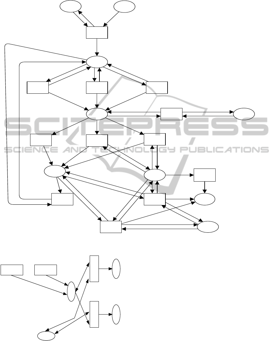
CPN model components. Figure 1 represents an ex-
ample of the structure, where some arc and guard
functions are omitted for readability.
1. Queuing and Dequeuing.
These components put transactions into the wait-
ing line outside the system, and take them out
of it for scheduling. In a CPN model, they can
be regarded as external entities of the model, and
therefore are expressed as a single place to hold
the transactions to be processed. In Figure 1, this
place is shown at the top of the figure, which is
labeled by “TRQ”.
2. Scheduling.
This component executes each dequeued transac-
tion according to a predefined scheduling algo-
rithm. The component is expressed in a CPN
model as a transition “Sch” to obtain a transac-
tion from the place “TRQ”, a place “SEQ” to give
a unique transaction id, a place “TQ” that repre-
sents an internal queue, and succeeding n parallel
transitions for concurrent execution. It is shown
in Figure 1, below the place “TRQ”.
3. Database Access.
This component manipulates databases by “in-
sert”, “update”, “delete”, or “select” operations.
The component is expressed in a CPN model as
a place to hold a database operation such as “se-
lect” or “update”, transitions for processing each
database, and a place to hold all the database
record instances. In Figure 1, the place labeled
“SQLR”, “DB”, “DBF”and the transition labeled
“DB1” and “DB2” belong to this component. In
order to represent the “buffering” operation, the
database is denoted by the two places “DB” and
“DBF”, which correspond to the buffer and final-
ized database respectively.
4. Exclusive Control.
This component performs one of the most impor-
tant functionality to preserve data integrity. The
simplest implementation by CPN is to use a tran-
sition for “lock” operation and a place to hold the
tokens representing lock acquisition and release.
CPNbasedDataIntegrityEvaluationforCloudTransactions
269

Each token is expressed as a list of the locks for
database records. In Figure 1, the transition “LC”
and the place “Lock” compose the component.
5. Logging.
This component stores the operation logs for
database related activities. In a CPN model, it
is expressed as a transition for log writing, and
a place for a log file, which are represented as the
transition “Log” and the place “LF” respectively
in Figure 1.
6. Commit and Abort.
These components respectively confirm or discard
the database update. Each of them is expressed as
a transition connected to the places representing
the databases and the log file. In Figure 1, the two
transitions “Commit” and “Abort” represent this
component, where the place “CMPL” is a place
to control the simulation (see below).
7. Other Complementary Components.
These components include “restart”, “backup”,
“reorganization”, and so on. They are used un-
der particular situations, e.g. database recovery.
Since this paper deals with data integrity in steady
operation, they are not included in the CPN mod-
els.
In addition to the above components for transaction
processing, several components to control the CPN
model are needed, which are used to repeat or termi-
nate the simulation. In Figure 1, the transition “End”,
“Post”, and the place “CMPL” compose such compo-
nents.
[Data Structure]
In Transaction processing, data integrity is defined as
that the database records within a system satisfy the
given constraints. In a CPN model, each database
record can be expressed as a token associated with a
color set. This color set represents the data type which
corresponds to the database schema for the database
record. However, the data types used in a CPN model
and database schema are mutually different, there-
fore we need to define the transformation rules be-
tween them. One of the simplest ways for this trans-
formation is to map the schema data types into “int”
for the numeric types, and into “string” for others in
CPN/ML. For example, the following color set defini-
tion represents a database schema with “integer” key
and “varchar” data.
colset DB = int;
colset Key = int;
colset Data = string;
colset KD = product Key * Data;
colset KD
List = list KD;
colset DB Record = product DB * KD List;
[Application Structure]
The purpose of modeling the application structure of
a transaction system is to reveal how each transaction
accesses the databases to simulate the interactions be-
tween them for consistency evaluation. A transaction
is an entity in a transaction system, and can be ex-
pressed as a token in a CPN model. This token is re-
quired to express the logic included in the transaction.
The required information from the application logic
is the order of database accesses, in order to eval-
uate data integrity. Therefore, this paper expresses
it as a list of data access information, or more con-
cretely, we represent each transaction as a product of
“transaction-id” and “database access list”, each ele-
ment of which is composed of “database id”, “access
type”, and “access key”. As color sets, they are ex-
pressed as follows.
colset Action = int;
colset SEQ = int;
colset State = int;
colset TID = int;
colset SQL = product DB * Action * Key * Data;
colset SQL
List = list SQL;
colset TranReq = product TID * SQL List;
colset Tran = product TID * SEQ * State *
SQL
List;
where the color set “Action” represents the type of
database operation, e.g. “1” represents “select”, “2”
represents “update” and so on. The color set “SEQ”
represents a unique transaction id.
4 INTEGRITY EVALUATION
The CPN models discussed in the previous section
are to be evaluated whether they satisfy the con-
straints expressed in the form of predicate logic for-
mulae. Unlike the model checkers, e.g. SPIN, SMV,
or LTSA, CPN is not equipped with the verification
capability. Therefore, we need to add constraint eval-
uation mechanism to the models. This mechanism
works every time a transaction issues “commit” or
“abort”, which makes the database update confirmed.
Therefore, the mechanism must be synchronized with
the “commit” and “abort” components of the CPN
model. One of the implementation of this mechanism
is shown in Figure 2 (This figure is denoted by a sim-
plified notation of CPN for readability). This mecha-
nism consists of
1. A place for synchronization with the “commit”
and “abort” components (The place “C” in Figure
ICSOFT2012-7thInternationalConferenceonSoftwareParadigmTrends
270
db_record
db_record
log_record
tran
(#1 tran, #2 tran, 1, #4 tran)
(#2 sqlr, 0)
(#2 sqlr, 0)
(#2 sqlr, 1)
db_record
db_record
sqlr
sqlr
sqlr
ll
updateLock(sqlr, ll)(#1 sqlr, #2 sqlr, 1)
sqlr
pushSql(tran)
pushSql(tran)
pushSql(tran)
tran
tran
tran
transTran(trq, n)
trq
n + 1
n
Log
Comit
LC
[lockCheck(sqlr, ll)]
DB2
[MySQL(sqlr,
db_record,2)]
DB1
End
[(#1 (#1 sqlr)) = 0]
T3T2T1
Sch
LF
Log
DB_Record
Lock
[]
Lock_List
DB
DB_Record
CMPL
CMPL
SQLRSQLR
TQ Tran
TRQ
IniTrq
TranReq
Seq
1
SEQ
Post
DBFAbort
Figure 1: CPN model for transaction processing.
Commit Abort
C
D
A
DBF
N
M
Figure 2: Integrity evaluation mechanism.
2).
2. A transition for assuring data integrity of which
guard function is boolean and logically equivalent
to the constraints for the integrity (Transition “A”
in Figure 2).
3. A transition for detecting the breaking of data in-
tegrity, of which guard function is boolean and
logically equivalent to the negation of the above
constraints (Transaction “D” in Figure 2).
4. Two output-only places, one of which is con-
nected to the above transition “A” to hold the
“OK” messages, and one of which is connected
to the above transition “D” to hold the error mes-
sages.
This mechanism works as follows.
1. When the “commit” or “abort” transition is fired,
a token to activate one of the evaluation transitions
“A” or “D” is provided into the place “C”. At this
moment, all the databases are confirmed.
CPNbasedDataIntegrityEvaluationforCloudTransactions
271

2. By marking the place “C” in Figur 2, the eval-
uation transitions “A” and “D” become eligible
to fire. The transition “A” is associated with the
guard which becomes true if the constraints are
satisfied. On the contrary, the transaction “D”
is associated with that which becomes true if the
constraints are NOT satisfied.
3. Under the control of the above guards, the transi-
tion “A” is activated if the integrity constraints are
satisfied. In such a case, a token is sent back to the
place “C”, and the succeeding transitions of the
“commit” or “abort” transitions become eligible
to fire. Otherwise, the transition “D” is activated,
and no token is sent back. Consequently, the suc-
ceeding processes of the corresponding transac-
tion is halted.
By adding the above mechanism to a CPN model
for transaction processing, erroneous transactions to
disturb the data integrity are detected based on the
constraints expressed in the form of predicate logic
formulae. The situation of the data integrity problems
is reported as a token in the place “D”.
5 CONCLUSIONS
Cloud computing environments, especially the PaaS
environments, provide us with the platforms for
highly productive development, flexible operation,
and easy maintenance of transaction systems. One of
the bottlenecks of them is the low capability of pre-
serving data integrity, which is often referred to as
“CAP theorem”. This paper presented a CPN based
modeling and evaluation techniques for transaction
systems from data integrity viewpoints.
Firstly, the definition of data integrity, which is
one of the most vague concepts in database systems
and applications, is introduced from three different
viewpoints, and then it is formalized using predicate
logic. Although there are a variety of transaction
management systems based on different technologies
and mechanism, the essential functionality is com-
mon and can be formally modeled.
The paper used CPN as a formalization and mod-
eling tool to express the behavior of transactions, and
the integrity rules are expressed within CPN models
using CPN/ML codes. The common functional com-
ponents among the different transaction management
systems, e.g. transaction queueing, scheduling, com-
mit, or abort, are represented as CPN structures with
appropriate CPN/ML codes for color, guard, and arc
functions. Integrity evaluation mechanism is also im-
plemented as a CPN structure, and is added to the
above CPN models. It evaluates the original CPN
models examining whether they satisfy the given in-
tegrity criteria.
The paper deals with the common functional-
ity among different transaction systems, however for
practical use, more platform dependent models are
needed, e.g. those for Google App Engine (GAE) or
Amazon E2C.
REFERENCES
Gray, J. and Reuter, A. (1993). Transaction Processing:
Concepts and Techniques. Morgan Kaufmann.
Harper, R., MacQueen, D., Milner, R., and Tofte, M.
(1997). The Definition of Standard ML. The MIT
Press.
Jensen, K. and Kristensen, L. (2009). Coloured Petri
Nets: Modeling and Validation of Concurrent Sys-
tems. Springer-Verlag.
Jensen, K., Kristensen, L. M., and Wells, L. (2007).
Coloured Petri Nets and CPN Tools for Modelling
and Validation of Concurrent Systems. In Inter-
national Journal on Software Tools for Technology
Transfer (STTT) Volume 9, Numbers 3-4, pages 213–
254. Springer-Verlag.
Martin, M. J. P., Quintales, L. A. M., and Garcia, M. N. M.
(2004). A Framework for the Modelling and Simu-
lation of Distributed Transaction Processing Systems
Using Coloured Petri Nets. In International Confer-
ence on Applications and Theory of Petri Nets, pages
351–270. Springer-Verlag.
Pritchett, D. (2008). BASE: An ACID alternative. In ACM
QUEUE Volume 6 Issue 3, pages 48–55. ACM.
Sanderson, D. (2009). Programming Google App Engine.
Oreilly & Associates Inc.
Shinkawa, Y. and Matsumoto, M. (2001). An Informa-
tion System View of Consistency and Integrity in En-
terprise Operations. In Proc. 3rd International Con-
ference on Enterprise Information Systems Volume 2,
pages 709–716.
Vliet, J. V. and Paganelli, F. (2011). Programming Amazon
EC2. Oreilly & Associates Inc.
ICSOFT2012-7thInternationalConferenceonSoftwareParadigmTrends
272
