
Towards the Integrated Simulation and Programming of Palletizing
Lines
Antonello Cal
`
o
1
, Davide Buratti
1
, Dario Lodi Rizzini
2
and Stefano Caselli
2
1
OCME S.r.l., Parma, Italy
2
University of Parma, Parma, Italy
Keywords:
Industrial Machine, Simulation, Visual Programming.
Abstract:
In this paper, we discuss the advantages and the issues of simulation and visual programming of palletizing
machines and, in general, palletizing lines, and we illustrate an integrated software tool suite that meets such
requirements. The increasing complexity of lines and the variability of product formats require a common
machine model for all the tools, together with the independence from visualization to allow software reuse
and extendibility. Furthermore, the model should also be able to include palletizing line components external
to the machine that are critical for performance and whose model is only partially known.
1 INTRODUCTION
Palletizing units have represented an important part
of manufacturing systems for decades. However, the
design of modern palletizing systems is facing new
challenges dictated by market demands, which in-
clude increasing production rates, the larger variabil-
ity in product packaging and formats, the thinner and
more fragile primary containers and products to be
palletized. The complexity of modern palletizing sys-
tems has increased: they have to ensure faster product
manipulation and to adapt online to different pallet
formats. This trend also challenges human operators,
whose skills often do not match the new generation of
machines.
Simulation and visual programming software
tools can help to meet the requirements for modern
palletizing units and assist both manufacturers and
end users. Several software packages have been pro-
posed for simulation of a machine component (Dong
et al., 2002), for integrated simulation and parame-
ters optimization of a manipulator (Kazi et al., 2002),
and for high-level simulation of manufacturing sys-
tems (Inukai et al., 2007). Few tools, however, inte-
grate simulation, programming and monitoring of a
complete palletizing line.
In our previous work (Argenti et al., 2010), we
proposed an integrated software tool suite for simula-
tion, programming and monitoring of palletizing ma-
chines. The tool suite had been designed for a line
of robot-based palletizing machines manufactured by
OCME S.r.l., but the underlying concepts are suitable
for a wide range of end-of-line machines. The pro-
posed application was able to handle several machine
configurations and some of these have been added
long time after the end of software design. How-
ever, new demands and requirements have come out
through the use and experience with the tool suite.
In particular, upstream or downstream components of
the palletizing line like transport conveyor belts or
end-line manipulators, which are not part of the pal-
letizing machine, are critical for the performance and,
thus, should be included in the simulation. Unfortu-
nately, the behavior of such components provided by
third-part manufacturers is often unknown. Further-
more, a customized version of the application is re-
quired with respect to both the machine model and the
user interface, when the tools are provided to a client.
A more modular and independent organization of the
software tools could simplify the customization.
In this paper, we discuss the advantages and the
issues of the integrated simulation, visual program-
ming and monitoring of palletizing machines with
their extensions and illustrate an improved software
tool suite to demonstrate our position. In particular,
we claim that an integrated simulator and programmer
that models machine logic and behavior avoiding un-
necessarily detailed physical description, can improve
and speed up the development and the programming
of a machine. The simulation and modeling should
also include components of the lines that can affect
the performance of the palletizing machine. When
377
Calò A., Buratti D., Lodi Rizzini D. and Caselli S..
Towards the Integrated Simulation and Programming of Palletizing Lines.
DOI: 10.5220/0004120903770382
In Proceedings of the 9th International Conference on Informatics in Control, Automation and Robotics (ICINCO-2012), pages 377-382
ISBN: 978-989-8565-22-8
Copyright
c
2012 SCITEPRESS (Science and Technology Publications, Lda.)
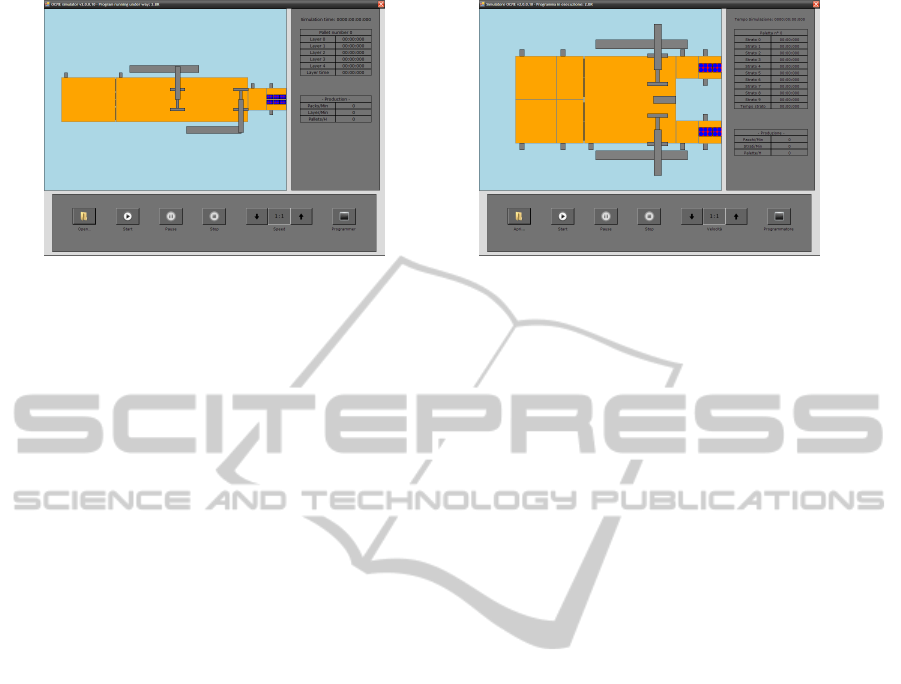
(a) (b)
Figure 1: Configuration of palletizers: single (a) or double (b) channel with arbitrary number and position of manipulators.
the behavior of such components cannot be fully de-
scribed, an approximate model can be used possibly
using a statistical model for some unknown variables
(e.g. the time required to perform a specific opera-
tion).
We also claim that the design of the tool
suite, while using a unique machine model for all
tools, should be inspired by the Model-View-Control
(MVC) software design paradigm, which allows code
reuse and ensures consistency among the behaviors
achieved by the applications. The new version of
the tool suite has been implemented using Microsoft
Expression Blend Framework (MEBF) to better meet
such requirements. Such framework allows a greater
independence of the machine model and control from
the visualization, since it manages interface as vector
graphics. Furthermore, the framework allows a more
modular organization of the suite: the application
consists of separate components, each described by
a XAML (eXtensible Application Markup Language)
file that specifies the graphic interface and the model
and control program.
The paper is organized as follows. Section 2 illus-
trates the common model of the palletizing machine
used by all tools. Section 3 describes the simulator.
Section 4 presents the visual programming tool for
the generation of control parameters. Finally, section
5 gives conclusion remarks.
2 MODEL OF THE PALLETIZING
MACHINE
The integrated tool suite for simulating, programming
and monitoring the palletizing lines is built on the
model of the system. Since the structure of a palletiz-
ing line as well as its core palletizing machine is sub-
ject to variability, the model consists of the composi-
tion of the elementary components of the system. The
accuracy level of each model depends on available in-
formation on the machine. A model should describe
the elementary components, the dimensional param-
eters, and the state of the machine. Since the aim of
the tool suite is to provide an user friendly interface
for palletizer management, the graphical representa-
tion of each component is as important as the list of
the attributes. However, the state of the machine is the
most critical part for machines that are provided by
third party manufacturers. Each tool uses the machine
model according to its own purposes. The simulator
modifies the state of the machine to emulate its be-
havior through state transitions. The monitoring tool
represents the current state of the palletizer according
to the messages received from the machine controller,
in the case there is a communication channel with the
controller. The programmer reads and writes the pa-
rameters that allow formation of pallet layers.
The model, the graphical representation and the
behavior of the machines palletizer should be inde-
pendent. The software design of the tool suite has
adopted the MVC paradigm that proposes such sep-
aration between the three aspects as a general design
criterion. Such approach has been applied to define
the palletizer components in (Argenti et al., 2010).
Figure 1 shows how the same components can be
reused to represent different machine configurations.
The same approach has been applied to model the
end-line manipulator that moves the already formed
pallet layers from the palletizing machine to the pal-
let layer stack. The end-line manipulator is not strictly
part of the machine, but it is manufactured by a third-
part producer. A complete model of the physical arm
and of its kinematics is either difficult to obtain be-
cause the information is unavailable or too complex
and detailed for our purposes. Thus, an approxi-
mate planar model of the manipulator has been ex-
ploited by partially reusing components designed for
the palletizer. The position of the manipulator com-
ICINCO2012-9thInternationalConferenceonInformaticsinControl,AutomationandRobotics
378
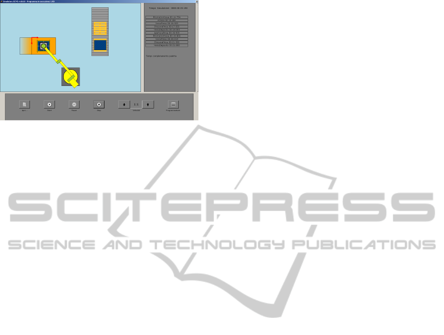
Figure 2: End-line manipulator to move and the formed
pallet layer from the palletizing machine (middle-left) to the
pallet layer stack (top-right).
ponents has been expressed with respect to a relative
frame. Figure 2 illustrates the graphical representa-
tion of the end-line manipulator. The design of the
machine model has proven sufficiently flexible and
robust to the introduction of this new palletizing line
element.
Although product units are not strictly part of the
machine, the concept of component has been conve-
niently extended also to units and group of units. A
component is defined as the basic part of the system
that contributes to the description of the system state.
Components also have a graphical representation and
their visualization is handled by proper routines. A
machine configuration is defined through a configura-
tion file in text format. During initialization, this file
is parsed and used to create the palletizer model with
the aggregation of the specified components. In the
future, we expect to convert the specifications con-
tained in the custom configuration file to the XAML
format to fully exploit the features of Microsoft Ex-
pression Blend Framework.
3 SIMULATOR
The proposed tool suite allows an accurate simula-
tion of the palletizing line to estimate its throughput
and the time required to complete specific production
steps. The simulating tool can also be used to dis-
play the final system to designers and customers. The
accuracy of simulation closely depends on the model
described in the previous session, since simulation is
essentially defined by the system state variables and
the transition function that modifies the value of state.
The simulation of the palletizing machine is fo-
cused on the product units. Indeed, the palletizing
machine operates on batches of product units in or-
der to arrange them into pallet layers. In this case,
the activity of each machine component is naturally
modeled as a queue or FIFO representing the sequen-
tial processing operated on product units as illustrated
in (Argenti et al., 2010).
The simulation of an external element like the
end-line manipulator illustrated in the previous sec-
tion has required a different approach. Indeed, the
end-line manipulator does not operate on single prod-
uct units or batches, but on pallet layers. Thus, the
FIFO interface, which is suitable to model the oper-
ations inside the palletizing machine, cannot be used
in this case. For this purpose, a hierarchy of simula-
tors and and a high level interface Simulator have
been defined. Simulator is a composite object that
allows the composition and joint management of mul-
tiple simulators. In this perspective, the palletizing
machine and the manipulator can share the same event
queue.
Each Simulator is responsible of the subsystem
state update. The state consists of both continuous
and logic variables. The transition events of logic
variables are handled at the beginning of a simulation
time interval as illustrated in (Argenti et al., 2010).
The coordination among the simulators is achieved
using the same simulation time step. In particular, the
global time step is adapted to the minimum update
time of the simulators (Zeigler et al., 2000).
3.1 The Queues of Palletizing Machine
The control and simulation of palletizing machine has
been decomposed in four queues or FIFOs: the in-
put conveyor belt queue, the manipulation queue, the
movable barriers queue and the conveyor belt queue.
As explained before a FIFO represent a specific oper-
ation or group of operations performed on the product
units that are stored in the FIFO.
The input conveyor belt queue controls the state of
the first group of two conveyor belts in each channel,
which separates product units in batches.
The manipulation queue controls the manipulators
that move product batches in the required position.
Since these manipulators are part of the machine, their
model and control is completely known (the finite
state machine is shown in Figure 3). The aim of these
manipulators is to place the batches that are not cor-
rectly aligned with respect to their final position in the
pallet layer. The manipulator can pick its target only
after a given position has been reached (third state di-
agram in Figure 3) and releases the product batch at a
given final position. Then, the arm moves toward the
new incoming batch, if there is one, or to a waiting
position (branching of state diagram).
The movable barriers queue controls the product
batches piling on the movable barriers located at the
TowardstheIntegratedSimulationandProgrammingofPalletizingLines
379
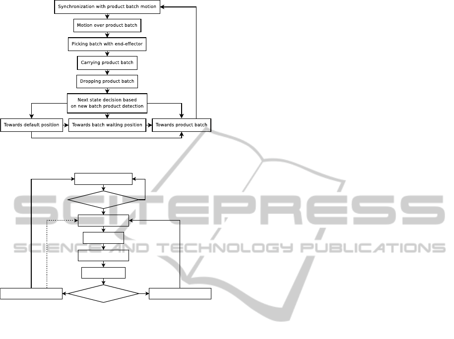
Figure 3: Finite state machine representing the manipulator
behavior.
Ready (Waiting Position)
Moving to Layer Area
Closing Arm Tool
Moving to Pallet Area
Opening Arm Tool
Moving to Waiting Position Moving to Layer Area
Layer Ready?
Layer Ready?
No
No
Yes
Yes
INTERRUPT:
Layer becomes
ready
Figure 4: Finite state machine approximating the behavior
of the end-line manipulator.
end of the manipulation conveyor belt. Barriers are
raised in order to form a section of the pallet and
are then lowered when the cumulated items are trans-
ferred to the merging conveyor belt. To avoid com-
penetration of product units, the simulator must han-
dle object collision. Management has be simplified
by assuming that all the incoming product units are
orthogonally oriented with respect to the barriers and
that the torques generated by contacts are negligible
independently from the contact surface. The accumu-
lation and contact has been handled using a segment
tree (De Berg et al., 2008).
The final conveyor belt queue controls the last
conveyor belt that transfers the formed pallet. The
number of configurations of the conveyor belt handled
by the simulator has been increased from the model
in (Argenti et al., 2010). In particular, pallet transfer
may be performed by a manipulator (discussed in the
next section), by a mechanical pusher, or by a lower-
ing platform.
3.2 End-line Manipulator
The manipulator is a component of the palletizing line
that is provided by a third party producer. In some
cases, the performance of a palletizing line depends
on the performance of the manipulator, e.g. when the
time required by the palletizer to form a pallet layer
is comparable with time required by the robot arm to
transport the layer. Thus, a simulation that aims at as-
sessing the throughput of the production line should
also consider the behavior of the robotic arm. Un-
fortunately, the knowledge of its physical and logical
model is usually incomplete and its exact behavior is
difficult to reproduce (i.e. the time required to execute
a motion).
Instead, the approximate finite state machine rep-
resented in Figure 4 has been used. The diagram is
similar to the finite state machine of the palletizer
manipulators. Since the transition time between two
states is only approximately known, the simulator re-
turns a time estimation proportional to the path length
or provided as an empirical constant. The user may
also choose to randomly generate the time according
to common statistical distributions (normal, negative
exponential, etc.).
The end-line manipulator does not operate on
product units or batches like the various parts of the
palletizing machine, but on already formed pallet lay-
ers. Hence, the simulation of its behavior cannot be
handled by a FIFO of product units. The control of
the end-line manipulator has been implemented as a
specific instance of Simulator interface. Such in-
terface may be integrated with other simulators like
the palletizer simulator to emulate the behavior of the
palletizing line.
4 PROGRAMMER
The aim of palletizing line programming is the gener-
ation of machine parameters consistent with the pallet
layer layouts specified by users. The human opera-
tor must only provide high level specification, choose
among the solutions proposed by the programming
tools according to convenient policies, and possibly
edit the solution. Finally, the tool generates the re-
quired parameters. These four steps are achieved by
the proposed tool that improves the previous version
illustrated in (Argenti et al., 2010).
4.1 Layout Generation
The computational counterpart of the physical layer
planning problem is the well-known bin packing
problem (Lodi et al., 2002), which is usually trans-
formed into an unidimensional knapsack problem.
ICINCO2012-9thInternationalConferenceonInformaticsinControl,AutomationandRobotics
380
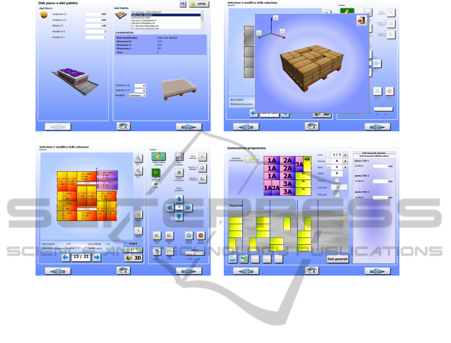
(a) (b)
(c) (d)
Figure 5: The four steps of the programming tool: the selection mask of pallet format and other requirements (a), layout
generation (b) and editing (c), and the batch decomposition and computation of machine parameters (d).
Unfortunately, bin packing algorithms assist in max-
imizing the number of product units per layer or pal-
let but do not consider other practical requirements
such as regularity in products arrangement, layer sta-
bility, and presence of symmetries. Alternative com-
putational approaches such as rectangular tessellation
and rectangle tiling suffer from similar drawbacks and
do not exploit special features of the problem such as
the uniform product size.
For these reasons, the proposed layout generation
system is based on a set of predefined patterns incor-
porating user expectations as well as typical indus-
trial requirements. The input data for layout compu-
tation consist of product size, allowed product over-
flow or required margin from pallet borders, and pal-
let style (plain or hierarchical). Figure 5(a) illustrates
the mask for inserting high level specifics like pal-
let format and product unit size. Then, the program-
mer generates possible pallet layer layouts according
to patterns like Binary Cut, Single Spiral, Column
and Double Spiral and maximizes the number of units
per layer (Figure 5(b)). The user can graphically edit
the found solutions through a drag-and-drop interface
and select the layouts to be used in each layer (Fig-
ure 5(c)). More details on layout patterns are avail-
able in (Argenti et al., 2010).
4.2 Batch Decomposition and
Parameters Computation
The second step of palletizer programming is the
computation of control parameters required to gener-
ate the given layout. The layout generated in the pre-
vious step consists of product units arranged inside
the planar shape of the pallet. Since the manipulation
of product units is oriented to batches, the decompo-
sition of the layouts in batches is crucial for parame-
ters computation. Batch formation must follow some
rules about maximum number and proximity of prod-
uct items. A batch corresponds to a group of units that
are manipulated together. Thus, its weight and size
are limited by the payload and the end-effector size
of the manipulators. Furthermore, the batch should
have single or double row rectangular shape depend-
ing on the machine configuration, since it is formed
through commands to the input conveyor belts. Batch
selection follows different rules. The sequence num-
ber of each batch must be consistent with the order
of accumulation. Batch feasibility is checked using
a graph-like data structure that represents proximity
relationships between units. The selection of batch
items can be performed manually, semi-automatically
or completely automatically.
TowardstheIntegratedSimulationandProgrammingofPalletizingLines
381

Given the batch decomposition of the pallet layer,
machine parameters are completely determined. The
parameters related to a batch include the number of
product items, the number of rows, the spacing from
the previous batch, the offset positions for manipu-
lation picking and release, the rotation flag, and the
offset positions for barrier raise and release. Barrier
offsets depend on the relative displacement of batches
in the pallet layer. Thus, the programmer divides the
batches in groups according to their alignment to a
common front line. Each group corresponds to prod-
uct batches simultaneously accumulated on the same
barrier. Figure 5(d) illustrates the final step of pro-
gramming tool with the batch numbering and the fi-
nal product unit sequence. The new version of the
programming tool allows parameter generation for a
larger number of machine configurations and supports
the addition of other machines.
5 CONCLUSIONS
In this paper, we have discussed the simulation and
programming of palletizing lines and have illustrated
the related issues through a tool suite developed for a
specific palletizer. A palletizing line consists of com-
ponents, whose behavior can be fully described or
only partially known. In the first case, the simulation
and the programming of the machine is better per-
formed on a common model. The simulation should
include the control logic and a kinematic model of
its parts sufficiently accurate to estimate the time, but
should also avoid unnecessary modelling of physical
interaction and dynamics of bodies. When the behav-
ior of some machine of the model is unknown, an ap-
proximate finite state diagram with empirical estima-
tion of transition times could be used. Such solution
is effective when such machine is not a bottle-neck of
the whole system.
The MVC design paradigm can effectively sup-
port software reuse and enforce consistency between
the different tools of the tool suite by separating the
management of data, graphical interface and logic
control. All the tools should be based on a common
model representing the structure of the machine, but
each tool should operate differently on the machine
data. Furthermore, a software organized in modu-
lar components allows customizable tools for the end
user.
All these design solutions have been derived from
a tool suite for the simulation, programming and mon-
itoring of a specific palletizing machine supporting
a high number of configurations. The simulator has
been extended to simulate an end-line manipulator us-
ing an approximate model. The programming tool as-
sists non-expert human operators in visual program-
ming of the palletizing task, and supports a variety
of configuration options automatically planning fea-
sible layers. The organization of the suite according
to Microsoft Expression Blend Framework has im-
proved the decoupling between model and interface.
The monitoring tool supports diagnostic activities and
allows efficient recovery when failure occurs. Fur-
thermore, it has enforced the modular subdivision of
the tools, e.g. the decomposition of the programming
steps, making possible a better customization of the
tool for a specific machine. The proposed tool suite
has been already successfully used by several opera-
tors on different palletizing lines in working plants.
ACKNOWLEDGEMENTS
This research has been supported by Regione Emilia-
Romagna, Italy, as part of the Integrapack project.
REFERENCES
Argenti, M., Buratti, D., Lodi Rizzini, D., and Caselli, S.
(2010). An integrated tool suite for simulation and
programming of palletizing units. In Proc. of the ISR
2010.
De Berg, M., Cheong, O., van Kreveld, M., and Overmars,
M. (2008). Computational Geometry, Algorithms and
Applications. Springer-Verlag, 3rd ed.
Dong, W., Palmquist, F., and Lidholm, S. (2002). A simple
and effective emulation tool interface development for
tricept application. In Proc. Int. Symp. on Robotics
(ISR).
Inukai, T., Hibino, H., and Fukuda, Y. (2007). Simulation
environment synchronizing real equipment for manu-
facturing cell. J. Advanced Mechanical Design, Sys-
tems, Manufacturing, 1(2):238–249.
Kazi, A., Merck, G., Otter, M., and Fan, H. (2002). Design
optimization of industrial robots using the modelica
multi-physics modelling language. In Proc. Int. Symp.
on Robotics (ISR).
Lodi, A., Martello, S., and Vigo, D. (2002). Recent
advances on two-dimensional bin packing problems.
Discrete Appl. Math., 123:379–396.
Zeigler, B. P., Praehofer, H., and Kim, T. G. (2000). Theory
of Modeling and Simulation. Academic Press, 2nd ed.
ICINCO2012-9thInternationalConferenceonInformaticsinControl,AutomationandRobotics
382
