
Managing Model Fidelity for Efficient Optimization of Antennas
using Variable-resolution Electromagnetic Simulations
Slawomir Koziel, Stanislav Ogurtsov and Leifur Leifsson
Engineering Optimization & Modeling Center, School of Science and Engineering, Reykjavik University, Reykjavik, Iceland
Keywords: Computer-aided Design (CAD), Simulation-driven Design, Antenna Design, Electromagnetic Simulation,
Surrogate Modelling.
Abstract: Electromagnetic (EM) simulation has become an important tool in the design of contemporary antenna
structures. However, accurate simulations of realistic antenna models are expensive and therefore design
automation by employing EM solver within an optimization loop may be prohibitive because of its high
computational cost. Efficient EM-driven antenna design can be performed using surrogate-based
optimization (SBO). A generic approach to construct surrogate models of antennas involves the use of
coarse-discretization EM simulations (low-fidelity models). A proper selection of the surrogate model
fidelity is a key factor that influences both the performance of the design optimization process and its
computational cost. Despite its importance, this issue has not yet been investigated in the literature. Here,
we focus on a problem of proper surrogate model management. More specifically, we carry out a numerical
study that aims at finding a trade-off between the design cost and reliability of the SBO algorithms. Our
considerations are illustrated using several antenna design cases. Furthermore, we demonstrate that the use
of multiple models of different fidelity may be beneficial to reduce the design cost while maintaining the
robustness of the optimization process.
1 INTRODUCTION
Design of contemporary antennas strongly relies on
electromagnetic (EM) simulations. For many
structures, including ultra-wideband (UWB)
antennas of non-canonical shapes (Shantz, 2005) or
dielectric resonator antennas (DRAs) (Petosa, 2007),
EM-based design is the only possibility to adjust
geometry and/or material parameters so that given
performance specifications are met. Typically, this is
performed through laborious parameter sweeps
guided by engineering experience, which does not
guarantee optimum results.
Automation of the antenna design process by
using numerical optimization routines is challenging
as high-fidelity EM simulation is computationally
expensive and conventional algorithms (e.g.,
gradient-based ones) require large number of such
simulations. Population-based techniques
(metaheuristics) have recently become popular in the
solving certain antenna-design-related tasks (Haupt,
2007); (Kerkhoff and Ling, 2007). Methods such as
genetic algorithms (Pantoja et al., 2007), particle
swarm optimizers (Jin and Rahmat-Samii, 2005) or
ant colony optimization (Halehdar et al., 2009), can
alleviate certain problems (e.g., getting stuck in a
local optimum); however, these methods are mainly
applicable if the objective function evaluation is
very fast, for example, for synthesis of antenna array
patterns (Jin and Rahmat-Samii, 2008). The use of
such techniques for simulation-based antenna design
is questionable due to the large number of model
evaluations required by metaheuristics.
In recent years, there has been a growing interest
in surrogate-based optimization (SBO) methods
(Bandler et al., 2004); (Koziel et al., 2006); (Koziel
et al., 2011), where direct optimization of a CPU-
intensive full-wave EM model is replaced by
iterative updating and re-optimization of a cheap and
yet reasonably accurate representation of the antenna
structure under consideration, by so-called surrogate
model. There are many techniques exploiting both
approximation surrogates, e.g., neural networks
(Rayas-Sánchez, 2004; Kabir et al., 2008), support
vector regression (Smola and Schölkopf, 2004);
(Meng and Xia, 2007), radial-basis functions
(Buhmann and Ablowitz, 2003), kriging (Simpson et
al., 2001); (Forrester and Keane, 2009), as well as
457
Koziel S., Ogurtsov S. and Leifsson L..
Managing Model Fidelity for Efficient Optimization of Antennas using Variable-resolution Electromagnetic Simulations.
DOI: 10.5220/0004147404570465
In Proceedings of the 2nd International Conference on Simulation and Modeling Methodologies, Technologies and Applications (SDDOM-2012), pages
457-465
ISBN: 978-989-8565-20-4
Copyright
c
2012 SCITEPRESS (Science and Technology Publications, Lda.)

physics-based surrogates (space mapping (Bandler et
al., 2004); (Amari et al., 2006); (Koziel et al., 2008),
simulation-based tuning (Swanson and Macchiarella,
2007); (Rautio, 2008); (Cheng et al., 2010),
manifold mapping (Echeverria and Hemker, 2005),
shape-preserving response prediction (Koziel,
2010a). Approximation models are fast and
universal, however, they are associated with the high
initial cost, which is due to sampling of the design
space and acquiring EM simulation data, and they
are typically not suitable for ad-hoc optimization.
Techniques exploiting physics-based surrogates are
particularly attractive because they are capable to
yield a satisfactory design using a very limited
number of expensive high-fidelity EM simulations
(Bandler et al., 2004).
One of the important assumptions to ensure
efficiency of the SBO techniques exploiting physics-
based surrogates is that the underlying low-fidelity
model is computationally cheap. The most
prominent technique of this kind is space mapping
(Koziel, 2010a). It is originated in the area of
microwave filter design where this assumption is
naturally satisfied by circuit equivalents (Bandler et
al., 2004) serving as low-fidelity models for filters.
In case of antennas, physics-based surrogates can be
obtained from coarse-discretization EM simulations
as this is the only versatile way to create lower-
fidelity antenna models. Unfortunately, such models
may be relatively expensive. As a result, their
evaluation cost cannot be neglected and may
contribute considerably to the overall design
expenses.
Therefore, the proper choice of the surrogate
model fidelity is of great significance. On one hand,
using a coarser low-fidelity model allows us to
reduce its evaluation time. On the other hand, the
coarser models are less accurate. As a result, a large
number of iterations of the SBO algorithm may be
necessary to yield a satisfactory design so that the
total cost may be about the same or even higher than
the total cost of an optimization algorithm
employing only the finer model. Moreover, the
surrogate-based optimization process may simply
fail if the underlying low-fidelity model is not
sufficiently accurate. For finer models, the
individual evaluation time may be higher, but this is
not directly translated into a higher total design cost
because a smaller number of iterations may be
sufficient to find a good design. In general, finding a
good trade-off between the low-fidelity model speed
and accuracy is not obvious.
Computational expenses of the low-fidelity
models which are built from coarse-mesh discrete
simulations can be alleviated to some extent on the
algorithmic level. For example, in space mapping,
the surrogate model parameters are repeatedly
extracted with nonlinear regression at every iteration
of the optimization algorithm (Koziel et al., 2006),
which results in a large number of low-fidelity
model evaluations and consequently in high total
costs. Unlike space mapping, response correction
techniques, e.g., manifold mapping (Echeverria and
Hemker, 2005), shape-preserving response
prediction (Koziel, 2010a), or adaptively adjusted
design specification method (Koziel, 2010b) do not
have these issues because no extractable parameters
are utilized there.
Here, we study the importance of the proper
selection of the antenna model fidelity and its
influence on performance of the surrogate-based
design process in terms of the computational cost
and design quality. We also investigate the potential
benefits of using several models of different fidelity
in the same optimization run. Our considerations are
based on several antenna design cases. The
presented results can be helpful to formulate
recommendations regarding the surrogate model
selection for simulation-based antenna design.
2 LOW-FIDELITY ANTENNA
MODELS
In this section, we formulate the antenna design task,
recall the generic surrogate-based optimization
(SBO) scheme, as well as discuss the issues
regarding the selection of the low-fidelity antenna
model that is a key component of physics-based
SBO methods.
2.1 Design Problem Formulation
The antenna design task can be formulated as a
nonlinear minimization problem
(
)
*
arg min ( )
ff
U∈
x
xRx
(1)
where Rf ∈ Rm denotes the response vector of a
high-fidelity (or fine) model of the antenna of
interest evaluated through expensive high-fidelity
EM simulation; x ∈ Rn is a vector of designable
variables. Typically, these are geometry and/or
material parameters. The response Rf(x) might be,
e.g., the modulus of the reflection coefficient |S11|
evaluated at m different frequencies. In some cases,
Rf may consists of several vectors representing, e.g.,
antenna reflection, gain, etc. U is a given scalar
SIMULTECH2012-2ndInternationalConferenceonSimulationandModelingMethodologies,Technologiesand
Applications
458

merit function, e.g., a norm, or a minimax function
with upper and lower specifications. U is formulated
so that a better design corresponds to a smaller value
of U. xf* is the optimal design to be determined.
2.2 Surrogate-based Optimization
In this work we consider surrogate-based
optimization (SBO) techniques (Koziel et al., 2011)
that aim at reducing the cost of EM-driven design by
shifting the optimization burden into a cheap and yet
reasonably accurate representation of the high-
fidelity model, a surrogate.
A generic SBO algorithm produced a series of
approximate solutions to (1), x(i), i = 0, 1, …, as
follows (Koziel, et al., 2011):
(1) ()
arg min ( ( ))
ii
s
U
+
=
x
xRx
(2)
where Rs(i) is the surrogate model at iteration i; x(0)
is the initial design Typically, the surrogate model is
updated after each iteration using the high-fidelity
model data accumulated during the optimization
process. Normally, the high-fidelity model is
referred to rarely, in many cases only once per
iteration, at a newly found design vector x(i+1). For
a well working algorithm, the number of iterations
necessary to find a satisfactory design is rather low.
This, in conjunction with the assumption of the
surrogate model being fast, allows us to significantly
reduce the computational cost of the design process
when compared with direct solving of the original
problem (1).
There are many ways of constructing surrogate
models that can be roughly split into approximation-
based and physics-based ones. Approximation
models are obtained by approximating sampled
high-fidelity model data using, e.g., neural networks
(Rayas-Sánchez, 2004)), kriging (Forrester and
Keane, 2009), or support-vector regression (Smola
and Schölkopf, 2004). This type of models are fast
and generic, and, therefore, easily transferrable from
one problem to another. There are several strategies
of allocating new samples and updating the model
and the one mentioned above (evaluating Rf at the
surrogate model optimum) is just one of them,
commonly used in local search. These, so-called
infill criteria (Forrester and Keane, 2009);
(Couckuyt et al., 2010), may be either focused on
exploration of the design space (aiming at improving
global accuracy of the model) or exploitation (local
search). Approximation model have one significant
disadvantage though: the initial cost of setting up the
surrogate is typically high because a large number of
samples may be necessary to ensure decent model
accuracy. This cost may not be justifiable for a one-
time design optimization of a given antenna
structure.
Here, we focus on physics-based surrogates
created from an underlying low-fidelity model Rc,
faster and yet reasonably representation of Rf. The
surrogate Rs(i) is obtained by aligning Rc with Rf at
the current design x(i) using Rf data accumulated in
previous iterations. Because the low-fidelity model
embeds some “knowledge” about the structure under
consideration, only a limited amount of high-fidelity
model data is necessary to correct Rc and the
generalization capability of the physics-based
surrogates (i.e., the ability to represent the high-
fidelity model outside the training set) is also much
better than for the approximation models.
2.3 Low-Fidelity Antenna Models
The only universal way of creating physics-based
low-fidelity antenna models is through coarse-
discretization EM simulation. This is particularly the
case for wideband and ultra-wideband (UWB)
antennas (Schantz, 2005), as well as dielectric
resonator antennas (DRAs) (Petosa, 2007) to name
just a few. In this paper, we assume that the low-
fidelity model Rc is evaluated with the same EM
solver as the high-fidelity model. The low-fidelity
model can be created by reducing the mesh density
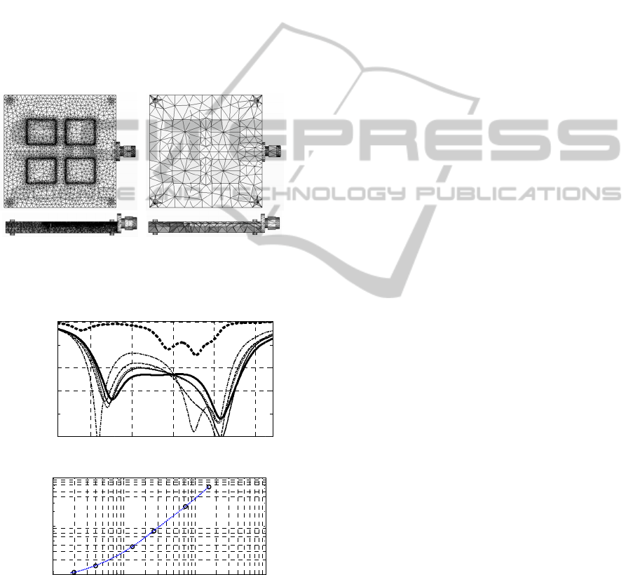
compared to the high-fidelity one as illustrated with
Fig. 1. Other options of the low-fidelity model may
include, among others: using smaller computational
domain with the finite-volume methods, using low
order basis functions with the finite-element and
moment methods, applying simple absorbing
boundaries, modelling metals with the perfect
electric conductor, neglecting metallization
thickness of traces, strips, and patches, ignoring
dielectric losses and dispersion.
Because of the possible simplifications, the low-
fidelity model Rc is (typically 10 to 50 times) faster
than Rf but not as accurate. Therefore, it cannot
substitute the high-fidelity model in design
optimization. Obviously, making the low-fidelity
model mesh coarser (and, perhaps, introducing other
simplifications) results in loss of accuracy but also
in a shorter computational time. Figure 2 shows the
plots illustrating the high- and low-fidelity model
responses at a specific design for the antenna
structure in Fig. 1, as well as the relationship
between the mesh coarseness and the simulation
time.
The selection of the low-fidelity model
coarseness is important for the computational cost
ManagingModelFidelityforEfficientOptimizationofAntennasusingVariable-resolutionElectromagneticSimulations
459
and per
fo
Coarser
lower c
o
models
a
larger
n
satisfact
o
that the
good de
more ex
p
a useful
As
m
of this
b
etween
antenna
model fi
Figure 1:
fidelity
E
low-fidel
i
(a)
(b)
Figure 2:
MWS tr
a
(a) the
r
density,
1
cells (–
–
1,588,60
8
versus th
e
|
S
11
| [dB]
1
1
1
Evaluation time [sec]
f
ormance of t
h
models a
r
e
o
st of per des
i
a
re also less
a
n
umber of it
e
o
ry design.
A
opti
m
ization
sign. Finer
m
p
ensive but t
h
design in a s
m
m
entioned in t
h
paper is
t
o
the perfor
m
design proc
e
delity.
(a)
A microstrip
E
M model with
i
ty EM model
w
An antenna
o
a
nsient solver
(
r
eflection resp
o
1
9,866 cells (▪
–
), 413,946 c
e
8
cells (▬); a
n
e
number of m
e
3
-25
-20
-15
-10
-5
0
10
4
1
0
2
1
0
3
1
0
4
T
h
h
e design opt
i
faster, whi
c
i
gn iteration.
a
ccurate, whic
h
e
rations nec
e
A
lso, there is
algorithm
w
m
odels, on th
e
h
ey are more
m
aller numbe
r
h
e introducti
o
o
investigate
m
ance of th
e
e
ss and the
u
(b)
antenna (Chen
,
a fine tetrahe
d
w
ith a coarse te
o
f Fig. 1 eval
u
(
CST, 2011) a
t
o
nse with dif
f
▪▪), 40,068 ce
l
e
lls (···), 740,
7
n
d (b) the ante
n
e
sh cells.
3.5 4
Frequency [G
H
10
5
1
h
e number of mes
h
i
mization pro
c
h translates
H
owever, co
a
h
may results
e
ssary to yie
l
an increased
w
ill fail to fi
n
e
other hand
,
likely to pro
d
r
of iteration.
o
n, the main f
o
the relatio
n
e
surrogate-
ba
u
nderlying c
o
,
2008): (a) a
h
d
ral mesh; and
trahedral mesh
.
u
ated with the
t
a selected de
fe
rent discretiz
a
l
ls (· ─ ·), 26
6
7
40 cells (—),
n
na evaluation
4.5 5
H
z]
1
0
6
1
0
h
cells
c
ess.
into
a
rser
in a
l
d a
risk
n
d a
,
are
d
uce
fo
cus
n
ship
ased
o
arse
h
igh-
(b) a
.
CST
sign:
ation
6
,396
and
time
stu
d
p
re
mo
d
hig
h
the
ess
e
im
p
tw
o
~4
0
rep
r
(sh
o
~2
7
on
e
as
cel
l
of
t
2.
4
Th
e
sur
r
ho
w
sur
r
inv
o
on
e
the
ev
a
sev
kin
d
He
m
et
a
(K
o
b
as
co
n
sca
l
the
lo
w
cor
r
wh
e
fun
the
C(i
)
ite
r
cor
r
or
d
mo
d
b
e
s
of
J[
R
0
7
Our conside
r
d
y; however,
s
ent stage o
r
d
el response
s
h
- and low-fi
d
model sele
c
e
ntial that t
h
p
ortant featur
e
Going back
t
o
“finest” c
0
0,000 and
r
esenting t
h
o
wn as a t
h
7
0,000 cells
c
e
. The two re
m
too coarse,
p
l
s; its respons
t
he high-fidel
i
4
Surro
ga
e
re are man
y
r
ogate from
a
w
ever, we ar
e
r
ogate model
o
lving multi
p
e
. The reason
number o
f
a
luations dur
i
eral more o
r
d
, such as
m
m
ker, 2005),
a
a
l., 2009), or
s
o
ziel, 2010a).
ic methods
n
siderations,
r
l
ing.
The respons
e
surrogate m
o
w
-fidelity m
o
r
ection functi
o
s
R
e
re C : Rm
ction. Here,
t
optimization
)
(Rc(x)), wh
e
ation i. For s
u
r
ection, we t
y
er consistenc
y
d
el is satisfi
e
s
hown (Alex
a
firs
t
-order
c
R
f(x(i))] (here
r
ations will b
it should b
e
research, vi
s
s
and the rel
a
d
elity models
c
tion proces
s
h
e low-fideli
t
e
s present in t
h
t
o Fig. 2, on
e
oarse-discreti
~740,000
e high-fidel
h
ick solid li
n
c
an be consi
m
aining mod
e
p
articularly t
h
e is substanti
a
ty model.
a
te Model
C
y
techniques
a
physics-
b
as
e
e
interested h
e
parameters c
a
p
le evaluatio
n
is that we a
i
f
high- an
d
n
g the desi
g
r
less involv
e
m
anifold ma
p
a
daptive resp
o
hape-
p
reserv
i
However, he
r
which are
r
esponse cor
r
e
correction t
e
del is constr
u
o
del respon
s
o
n as follows
:
() ( (
s
c
=
xCR
x
→ Rm is
a
t
he surrogate
process (2) i
s
e
re C(i) is the
u
rrogates con
s
y
pically req
u
y
between th
e
d, i.e., Rs(i)(
x
a
ndrov et al.,
c
onsistency,
, J[·] denote
s
b
e based on
n
e
stressed th
a
sual inspecti
o
ationship bet
w
is an import
a
s
. In particu
t
y model ca
p
h
e high-fideli
t
e
can observ
e
i
zation mod
e
cells) are
l
ity model
n
e). The m
o
i
dered as a
b
e
ls could be c
o
t
he one with
a
lly deviated
C
onstructi
o
for constru
c
e
d low-fideli
t
e
re in those
w
a
n be obtaine
d
n
s of the lo
w
i
m at minimi
z
d
low-fidelit
y
g
n
p
rocess.
T
ed technique
p
ping (Echev
o
nse correcti
o
i
ng response
p
r
e, we focus
o
sufficient
r
ection and
f
e
chnique ass
u
u
cted by com
p
s
e with a
:
))
x
a
response
c
model at iter
s
defined as
R
e
correction f
u
s
tructed usin
g
u
est that at l
e
e
surrogate an
x(i)) = Rf(x(
i
1998) that s
a
i.e., J[Rs(i)
(
s the Jacobi
a
n
umerical
a
t, at the
o
n of the
w
een the
a
nt step in
l
ar, it is
p
tures all
t
y one.
e
that the
e
ls (with
properly
response
o
del with
b
orderline
o
nsidered
~20,000
from that
o
n
c
ting the
t
y model,
w
here the
d
without
w
-fidelity
z
ing both
y
model
T
here are
s of this
e
rria and
o
n (Koziel
p
rediction
o
n the two
for our
f
requency
u
mes that
p
osing the
suitable
(3)
c
orrection
a
tion i of
R
s(i)(x) =
u
nction at
g
response
e
ast zero-
d
the fine
i
)). It can
a
tisfaction
(
x(i))] =
a
n of the
SIMULTECH2012-2ndInternationalConferenceonSimulationandModelingMethodologies,Technologiesand
Applications
460

respective model), guarantees convergence of {x(i)}
to a local optimum of Rf assuming that (3) is
enhanced by the trust region mechanism (Conn et
al., 2000) and the functions involved are sufficiently
smooth.
In this paper, we only consider a basic response
correction, i.e.,
() ()
( ( )) ( ) [ ( ) ( )]
ii
ccf c
=+ −CR x R x R x R x
(4)
This type of correction ensures a zero-order
consistency, i.e., Rs(i)(x(i)) = Rf(x(i)).
Another type of basic technique for surrogate
model construction considered here is a frequency
scaling. It is useful because, in many cases, the
major discrepancy between the high- and low-
fidelity model responses is a frequency shift, which
can be easily reduced by means of simple scaling
functions parameterized by just a few coefficients.
Here, we consider an affine scaling defined as F(ω)
= f0 + f1ω (Koziel et al., 2006), where f0 and f1 are
unknown parameters to be determined. Assuming
that the model responses correspond to evaluation of
the figures of inteters (e.g., S-parameters) at a set of
frequencies, i.e., Rc(x) = [Rc(x,ω1), …,
Rc(x,ωm)]T. The frequency scaled model is then
defined as
.1
( ) [ ( , ( )),..., ( , ( ))]
T
cF c c m
RF RF
ωω
=Rx x x
(5)
where the scaling parameters obtained by
minimizing the matching error
() () 2
01
1
[( ,) ( , )]
m
ii
fkc k
k
RRff
ωω
=
−+
∑
xx
(6)
It should be noted that the frequency scaling
parameters can be obtained without referring to an
EM simulation because all the necessary responses
Rc(x(i),f0 + f1ωk) can be obtained by interpolating/
extrapolating the know values Rc(x(i),ωk), k = 1,
…, m.
3 CASE STUDY I: SELECTING
MODEL FIDELITY
We consider two antenna design cases with the
optimized designs found using an SBO algorithm of
the type (2). For each case, we consider three low-
fidelity EM models of different mesh density. We
investigate the performance of the SBO algorithm
working with these models in terms of the
computational cost and the quality of the final
design.
3.1 Design of Broadband Slot Antenna
Consider a CPW-fed slot antenna shown in Fig. 3(a)
(Jiao et al., 2007). The design variables are x = [ax
ay a b s1]T; w0 = 4 mm, s0 = 0.3 mm. The substrate,
0.813 mm Rogers RO4003C (ε1 = 3.38 at 10 GHz),
and the ground plane are of infinite lateral extends.
The initial design is x
(0)
= [40 25 10 20 2]
T
mm. The
design specifications are |S11| ≤ –12 dB for 2.3-to-
7.6 GHz. The high-fidelity model Rf is evaluated
with the CST MWS transient solver (CST, 2011)
(3,556,224 mesh cells, simulated in 60 min). We
consider three coarse models (all evaluated in CST
MWS): Rc1 (110,208 mesh cells, 1.5 min), Rc2
(438,850, 5 min), and Rc3 (1,113,840, 8 min).
Figure 3(b) shows the responses of Rf and Rc1
through Rc3 at the initial design. Because of mostly
the vertical shift between the low- and the high-
fidelity model responses, the surrogate model for the
algorithm (1) is created using output space mapping
(OSM) (Bandler et al., 2004) so that Rs(i)(x) =
Rck(x) + [Rf(x(i)) – Rck(x(i))] (k is an index of a
respective low-fidelity model), cf. (4). Table 1 and
Fig. 3(c) show the optimization results. All the low-
fidelity models are relatively reliable here and the
qualities of the final designs are comparable. The
design cost is the smallest for the SBO algorithm
working with Rc1 even though five design iterations
are necessary. The algorithm working with Rc2 and
Rc3 require only 3 and 2 iterations, respectively, but
they are relatively expensive compared to Rf. Thus,
in this case, using the coarsest model is the most
advantageous.
3.2 Design of Microstrip Antenna
Consider a coax-fed microstrip antenna shown in
Figs. 4(a) and 4(b) (Wi et al., 2007). Design
variables are x = [a b c d e l0 a0 b0]T. The antenna
is on 3.81 mm thick Rogers TMM4 (ε1 = 4.5 at 10
GHz); lx= ly= 6.75 mm. The ground plane is of
infinite extends. The feed probe diameter is 0.8 mm.
The connector’s inner conductor is 1.27 mm in
diameter. Design specifications are |S11| ≤ –10 dB
for 5 GHz to 6 GHz. The high-fidelity model Rf is
evaluated with CST MWS transient solver (CST,
2011) (704,165 mesh cells, evaluation time 60 min).
We consider three coarse models: Rc1 (41,496, 1
min), Rc2 (96,096, 3 min), and Rc3 (180,480, 6
min). The initial design is x(0) = [6 12 15 1 1 1 1 –
4]T mm. Figure 4(c) shows the responses of all the
models at the approximate optimum of Rc1. The
major misalignment between the responses is due to
the frequency shift so that the surrogate is created
ManagingModelFidelityforEfficientOptimizationofAntennasusingVariable-resolutionElectromagneticSimulations
461
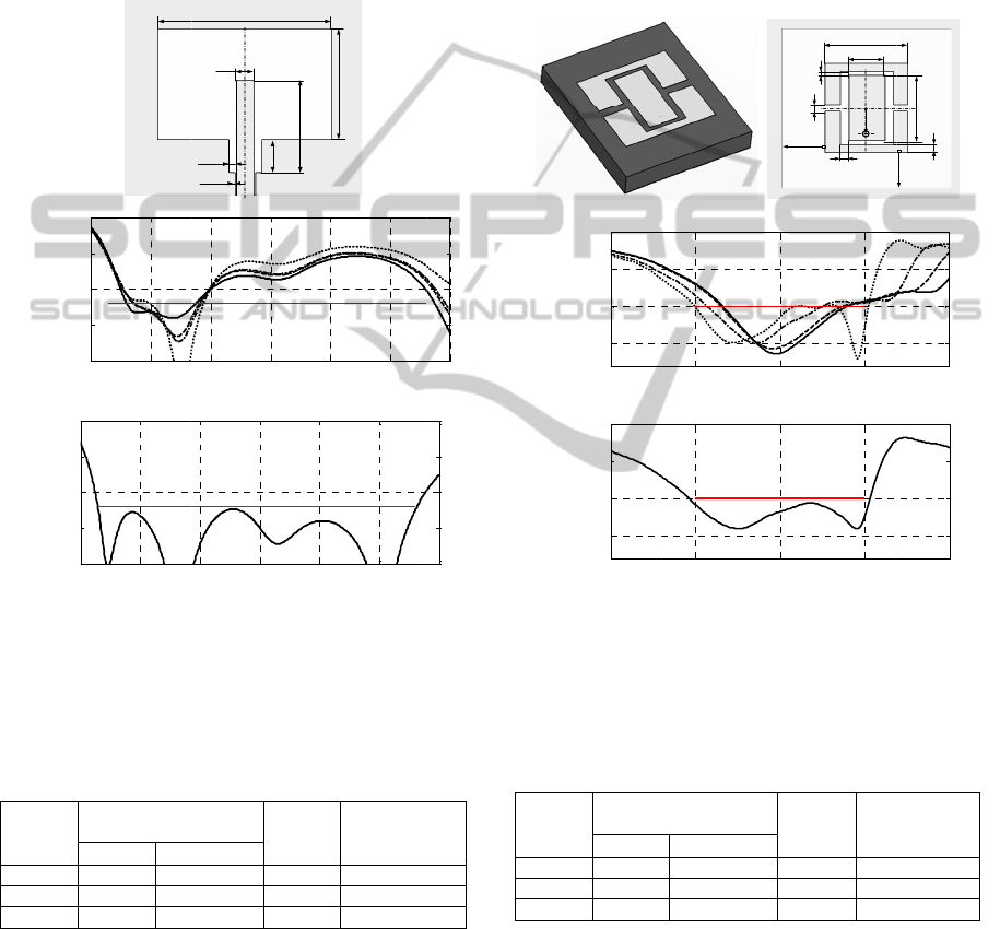
here usi
n
2006) a
s
2004).
T
that the
design
p
design.
T
satisfy t
h
p
rocess
u
Rc3.
(b)
(c)
Figure 3:
(Jiao et
design,
R
high-fide
l
using the
Ta
b
Low-
Fidelity
Model
Rc1
Rc2
Rc3
1 Number
iterations i
2 Equival
e
-
2
-
1
-
1
|
S
11
| [dB]
-2
0
-1
5
-1
0
-
5
0
|
S
11
| [dB]
n
g frequency
s well as o
u
T
he results,
T
model Rc1
i
p
rocess using
T
he designs f
o
h
e specificat
i
u
sing Rc2 is
s
(a)
ε
1
CPW-fed bro
a
al., 2007), (b
)
R
c1 (⋅⋅⋅), Rc2 (
⋅
l
ity model re
s
low-fidelity m
o
b
le 1: CPW-fed
Design Cost:
N
Model Evalu
a
Rc
287
159
107
of Rf evaluati
o
n (2).
e
nt number of R
f
2 3
2
0
1
5
1
0
-5
0
2 3
0
5
0
5
0
scaling (5),
(
u
tput SM (4
)
T
able 2 and
F
i
s too inaccu
r
it fails to f
i
o
und with mo
i
ons and the
s
lightly lowe
r
1
w
0
s
1
s
0
a
x
a
b
a
dband slot an
t
)
model resp
o
⋅
-⋅-), Rc3 (- -
-
s
ponse at the
o
del Rc3.
slot antenna –
d
N
umber of
a
tions1
Rela
t
Des
i
Cos
Rf
5 12.
3 16.
2 16.
o
ns is equal to
f
evaluations.
4 5
Frequency [G
H
4 5
Frequency [GH
z
(
6) (Koziel e
t
(Bandler et
F
ig. 4(d), ind
i
r
ate and the
S
i
nd a satisfa
c
dels Rc2 and
cost of the
S
r
than while
u
GND
a
y
b
t
enna: (a) geo
m
o
nses at the i
n
-
), and Rf (—
)
final design
fo
d
esign results.
t
ive
gn
t
2
max|S11|
fo
GHz to 8
G
at Final De
2
–12.1 d
B
2
–12.0 d
B
3 –12.3 d
B
the number of
6 7
H
z]
6 7
z
]
t
al.,
t
al.,
i
cate
S
BO
c
tory
Rc3
S
BO
u
sing
m
etry
n
itial
)
, (c)
f
ound
f
or 2
G
Hz
e
sign
B
B
B
SBO
4
In
t
fid
e
sur
r
res
o
b
e
n
wit
h
(
c
(
d
Fig
u
(a)
init
i
(d)
usi
n
T
L
Fi
d
M
R
R
R
1 N
u
iter
a
2 E
q
D
R
an
o
m
m
x
=
8
8
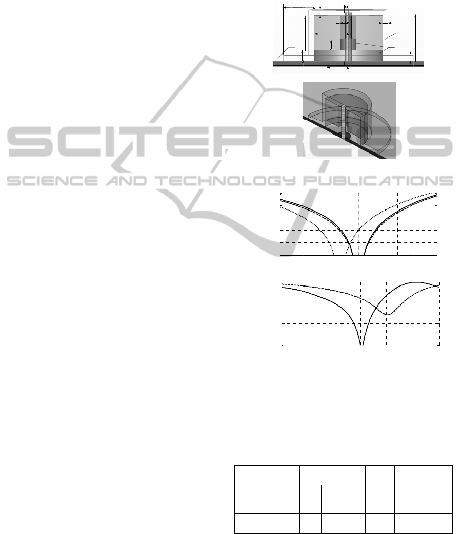
CASE S
T
MANA
G
t
his section,
w
e
lity models
r
ogate-
b
ased
d
o
nator anten
n
n
efits of usin
g
h
in a single o
p
(a)
c
)
d
)
u
re 4: Coax-fe
d
3D view; (b)
i
al design, Rc1
high-fidelity
m
n
g the low-fide
l
T
able 2: Coax-f
e
L
ow-
d
elity
M
odel
Design
C
Model
Rc
R
c1 385
R
c2 185
R
c3 121
u
mber of Rf e
v
a
tions in (2).
q
uivalent numbe
r
Consider a
h
R
A is fed by
a
o
pen ended s
e
m
thick Roger
=
[h0 r1 h1 u
l
4.5
-15
-10
-5
0
|
S
11
| [dB]
4.5
-15
-10
-5
0
|
S
11
| [dB]
T
UDY II:
G
EMENT
w
e again co
n
of variou
s
d
esign optimi
n
a. We also
g
two mode
l
p
timization r
u
d
microstrip a
n
top view, (c)
(⋅⋅⋅), Rc2 (⋅-⋅-)
,
m
odel response
l
ity model Rc3.
e
d microstrip a
n
C
ost: Number of
Evaluations1
Rf
6
3
2
v
aluations is eq
u
r
of Rf evaluatio
n
h
ybrid DRA
50 ohm mic
r
e
ction. Micro
s
s
RT5880. T
h
l
1 r2]T. Othe
r
55
.
Frequen
c
55
Frequen
c
MODEL
DRA DE
S
n
sider the us
e
s
mesh de
n
i
zation of the
investigate
l
s of differe
n
u
n.
GND
ε
1
a
b
a
0
d
c
l
0
l
x
l
y
(b)
n
tenna (Wi et
model respo
n
, Rc3 (- - -), a
n
at the final de
s
n
tenna – desig
n
Relative
Design
Cost2
max
GH
z
at Fi
n
12.4
–
12.3 –
14.1 –
u
al to the num
b
n
s.
shown in Fi
g
r
ostrip termi
n
strip substrat
e
h
e design var
i
r
dimensions
a
.
5 6
c
y [GHz]
.5 6
c
y [GHz]
S
IGN
e
of low-
n
sity for
dielectric
potential
n
t fidelity
b
0
e
al., 2007):
n
ses at the
n
d Rf (—),
s
ign found
n
results.
|S11| for 2
z
to 8 GHz
n
al Design
–
8.0 dB
1
0.0 dB
1
0.7 dB
b
er of SBO
g
. 5. The
n
ated with
e
is 0.787
i
ables are
a
re fixed:
6.5
6.5
SIMULTECH2012-2ndInternationalConferenceonSimulationandModelingMethodologies,Technologiesand
Applications
462
r0=0.63
5
of the D
b
oth at
1
(ε2=2.1)
(ε3 = 2.
7
p
lane op
The
evaluate
d
Microw
a
evaluati
o
geometr
y
specific
a
to 5.8
G
2.0 2.0
2
We
c
fidelity,
min), a
n
min).
W
one of t
h
and Rc2
construc
frequen
c
importa
n
the sha
p
model r
e
misalig
n
The
p
erform
e
using R
c
the sur
r
expensi
v
the sur
r
iteration
(Case 3
)
the app
r
then ref
i
number
to 100 (
w
the firs
t
iteration
s
required
)
Tabl
e
three c
a
model r
e
SBO al
g
Rc2. T
h
cases is
using th
e
more it
e
Rc2 (C
a
accurate
comput
a
lower f
o
cheapes
t
5
, h2=2, d=1,
D
RA core is 3
6
1
0 GHz. The
D
, and the
r
7
and tanδ =
0
p
ening, shown
high-fidelit
y
d
using the
a
ve Studio (C
S
o
n time 60
m
y
paramete
r
a
tions are me
t
G
Hz. The initi
a
2
.0]T mm.
c
onsider two
Rc1 (~45,0
0
n
d Rc2 (~300
,
W
e investigate
h
ese models
o
in the later
s
ted using b
o
c
y scaling (5
)
n
ce of the fr
e
p
e similarity
e
sponses allo
w
n
ment betwee
n
DRA des
i
e
d three time
s
c
1 – cheaper
r
ogate cons
t
v
e but also m
o
r
ogate const
ru
and with
R
)
. The last o
p
r
oximate hig
h
fi
ne it using
t
of surrogate
m
w
hich involv
e
t
iteration a
n
s (smaller
)
.
e
3 shows t
h
a
ses. Figure
e
sponse at the
g
orithm wor
k
h
e quality of
the same.
H
e
low-fidelit
y
e
rations than
t
a
se 3), which
. In this
p
a
tional cost
o
o
r Rc1 than f
o
t
approach is
r3= 6, all in
6
, and the lo
s
D
RA support
r
adome is
o
0
.01). The ra
d
in Fig. 5(b),
i
y
antenna
m
time-domai
n
S
T, 2011) (~
1
m
inutes). The
r
s so that
t
: |S11| ≤ –12
a
l design is
x
auxiliary m
o
0
0 meshes,
e
,
000 meshes,
the algorith
m
o
r both (Rc1
s
tages). The s
u
o
th output
S
)
, (6). Figur
e
e
quency scali
n
of the high-
w
s substantia
l
n
them.
i
gn optimiz
a
s
: (i) the sur
r
but less accu
t
ructed usin
g
o
re accurate
(
ru
cted with
R
R
c2 for sub
s
p
tion allows
u
h
-fidelity mo
d
t
he more acc
u
m
odel evalu
a
e
s the largest
n
d to 50 i
n
design m
o
h
e optimizati
o
6(b) shows
final design
o
k
ing with l
o
the final des
H
owever, th
e
y
model Rc1
t
he algorith
m
is because
t
p
articular c
a
o
f the desig
n
o
r Rc2. On t
h
Case 2 when
mm. Permitt
i
s
s tangent is
1
m
aterial is T
e
o
f polycarb
o
d
ius of the gr
o
i
s 2 mm.
m
odel Rf(x
)
n
solver of
C
1
,400,000 me
s
goal is to a
d
the follo
w
dB for 5.15
G
x
(0) = [7.0 7.
0
o
dels of diff
e
e
valuation ti
m
evaluation ti
m
m
(2) using e
i
at the initial
s
u
rrogate mo
d
S
M (4) and
e
6(a) shows
n
g, which, d
u
and low-fid
e
l
reduction o
f
a
tion has
b
ogate constr
u
r
ate (Case 1)
,
g
Rc2 –
m
(
Case 2), and
R
c1 at the
s
equent itera
t
u
s to faster l
o
d
el optimum
u
rate model.
a
tions was li
m
d
esign chang
e
n
the subse
q
o
difications
o
n results fo
r
the high-fid
e
o
btained usin
g
o
w-fidelity
m
igns found i
n
e
SBO algor
i
(Case 1) req
u
m
using the
m
t
he latter is
m
a
se, the ov
e
n
process is
h
e other hand
,
the model R
c
i
vity
1
0-4,
e
flon
o
nate
o
und
)
is
C
ST
s
hes,
d
just
w
ing
G
Hz
0
5.0
e
rent
m
e 1
m
e 3
i
ther
s
tate
d
el is
the
the
u
e to
elity
f
the
b
een
u
cted
,
(ii)
m
ore
(iii)
first
t
ions
o
cate
and
The
m
ited
e
) in
q
uent
are
r
all
elity
g
the
m
odel
n
all
i
thm
u
ires
m
odel
m
ore
erall
still
,
the
c
1 is
util
nu
m
sw
i
us
nu
m
tot
a
Fig
u
(
a
(
b
Fig
u
mo
d
(- -
mo
d
des
i
lo
w
Ca
s
1
2
3
1 N
u
iter
a
2 E
q
ized in the fi
r
m
ber of EM
i
tches to Rc2
i
to both red
u
m
ber of evalu
a
a
l design cost
(a)
h
1
u
r
3
GND
(b)
u
re 5: Hybrid
D
a
)
b
)
u
re 6: Hybrid
d
el Rc2 respon
s
-) applying t
h
d
el response at
i
gn obtained u
s
-fidelity model
Table 3
s
e
Number of
Iterations
N
4
2
2
u
mber of Rf e
v
a
tions in (1).
q
uivalent numbe
r
5.4
-40
-35
-30
-25
-20
-15
|
S
11
| [dB]
4
4
-30
-20
-10
0
|S
11
| [dB]
r
st iteration t
h
analyses,
w
i
n the second
u
ce the nu
m
a
tions of Rc2
is the lowest
o
r
2
r
1
r
0
1
d
h
2
l
1
D
RA: (a) side v
i
DRA: (a) hig
h
s
e at certain de
s
h
e frequency
s
the initial desi
g
s
ing the SBO
a
Rc2 (—).
: Hybrid DRA
d
N
umber of Mod
e
Evaluations1
Rc1 Rc2 R
f
250 0 4
0 150 2
100 50 2
v
aluations is eq
u
r
of Rf evaluatio
n
5.5 5
.
Frequen
c
4
.5 5
5
Frequen
c
h
at requires t
h
w
hereas the
a
iteration, whi
m
ber of itera
t
2
at the same
t
o
verall.
ε
1
ε
2
ε
3
d
d
i
ew; (b) 3D-cu
t
g
h- (—) and l
o
sign before (⋅⋅⋅⋅
scaling, (b) hi
g
n (- - -) and
a
algorithm usin
g
design results.
e
l
Total
Design
Cost2
ma
x
5.15
G
H
D
f
8.2 –
9.5 –
6.2 –
u
al to the num
b
n
s.
.
6 5.7
c
y [GHz]
5
.5 6 6.
c
y [GHz]
h
e largest
a
lgorithm
ch allows
t
ions and
t
ime. The
h
0
t
view.
o
w-fidelity
) and after
gh-fidelity
a
t the final
g
with the
x
|S11| for
GHz to 5.8
H
z at Final
D
esign
1
2.6 dB
1
2.6 dB
1
2.6 dB
b
er of SBO
5.8
5 7
ManagingModelFidelityforEfficientOptimizationofAntennasusingVariable-resolutionElectromagneticSimulations
463

5 DISCUSSION
Our results allow us to draw some conclusions
regarding the selection of the model fidelity for
surrogate-based antenna optimization. Using the
cheaper (and less accurate) model may translate into
lower design cost; however, it also increases the risk
of failure. Using the higher-fidelity model may
increase the cost but it definitely improves the
robustness of the SBO design process and reduces
the number of iterations necessary to find a
satisfactory design. Visual inspection of the low-
and high-fidelity model responses remains—so far—
the most important way of accessing the model
quality, which may also give a hint which type of
model correction should be applied while creating
the surrogate.
The following rules of thumb can be formulated
in order to facilitate the model selection process:
• An initial parametric study of low-fidelity model
fidelity should be performed at the initial design in
order to find the “coarsest” model that still
adequately represents all the important features of
the high-fidelity model response. The assessment
should be done by visual inspection of the model
responses having in mind that the critical factor is
not the absolute model discrepancy but the similarity
of the response shape (e.g., even relatively large
frequency shift can be easily reduced by a proper
frequency scaling).
• When in doubt, it is safer to use a slightly finer
low-fidelity model rather than a coarser one so that
potential cost reduction is not lost due to a possible
algorithm failure to find a satisfactory design.
• The type of misalignment between the low- and
high-fidelity models should be observed in order to
properly select the type of low-fidelity model
correction while constructing the surrogate. The two
methods considered in this paper (additive response
correction and frequency scaling) can be considered
as safe choices for most situations.
It should be emphasized that for some antenna
structures, such as some narrow-band antennas or
wideband travelling wave antennas, it is possible to
obtain quite good ratio between the simulation times
of the high- and low-fidelity models (e.g., up to 50),
which is because even for relatively coarse mesh, the
low-fidelity model may still be a good representation
of the high-fidelity one. For some structures (e.g.,
multi-resonant antennas), only much lower ratios
(e.g., 5 to 10) may be possible, which would
translate into lower design cost savings while using
the surrogate-based optimization techniques.
6 CONCLUSIONS
A problem EM simulation model management for
surrogate-based optimization of antennas has been
addressed. We have discussed a trade-off between
the computational complexity and accuracy of the
low-fidelity EM antenna models and their effects on
the performance of the surrogate-based optimization
process. Our considerations are illustrated using
several antenna design cases. Recommendations
regarding low-fidelity model selection are also
formulated. We also demonstrate that by proper
management of the models involved in the design
process one can lower the overall optimization cost
without compromising the final design quality.
ACKNOWLEDGEMENTS
The authors would like to thank CST AG for making
CST Microwave Studio available. This work was
supported in part by the Icelandic Centre for
Research (RANNIS) Grant 110034021.
REFERENCES
Alexandrov, N. M., Dennis, J. E., Lewis, R. M., Torczon,
V., 1998. A trust region framework for managing use
of approximation models in optimization. Struct.
Multidisciplinary Optim., vol. 15, no. 1, pp. 16-23.
Amari, S., LeDrew, C., Menzel, W., 2006. Space-mapping
optimization of planar coupled-resonator microwave
filters. IEEE Trans. Microwave Theory Tech., vol. 54,
no. 5, pp. 2153-2159.
Bandler, J. W., Cheng, Q. S., Dakroury, S. A., Mohamed,
A. S., Bakr, M. H., Madsen, K., Søndergaard, J., 2004.
Space mapping: the state of the art,” IEEE Trans.
Microwave Theory Tech., vol. 52, no. 1, pp. 337-361.
Buhmann, M. D., Ablowitz, M. J., 2003. Radial Basis
Functions: Theory and Implementations, Cambridge
University.
Chen, Z.N., 2008. Wideband microstrip antennas with
sandwich substrate. IET Microw. Ant. Prop., vol. 2,
no. 6, pp. 538-546.
Cheng, Q. S., Rautio, J. C., Bandler, J. W., Koziel, S.,
2010. Progress in simulator-based tuning—the art of
tuning space mapping. IEEE Microwave Magazine,
vol. 11, no. 4, pp. 96-110.
Conn, A. R., Gould, N. I. M., Toint, P. L., 2000. Trust
Region Methods, MPS-SIAM Series on Optimization.
Couckuyt, I., Declercq, F., Dhaene, T., Rogier, H.,
Knockaert, L., 2010. Surrogate-based infill
optimization applied to electromagnetic problems. Int.
J. RF and Microwave CAE, vol. 20, No. 5, pp. 492-
501.
SIMULTECH2012-2ndInternationalConferenceonSimulationandModelingMethodologies,Technologiesand
Applications
464

CST Microwave Studio, 2011. CST AG, Bad Nauheimer
Str. 19, D-64289 Darmstadt, Germany.
Echeverria, D., Hemker, P. W., 2005. Space mapping and
defect correction. CMAM The International
Mathematical Journal Computational Methods in
Applied Mathematics. vol. 5, no. 2, pp. 107-136.
Forrester, A. I. J., Keane, A. J., 2009. Recent advances in
surrogate-based optimization, Prog. in Aerospace
Sciences, vol. 45, no. 1-3, pp. 50-79.
Halehdar, A., Thiel, D. V., Lewis, A., Randall, M., 2009.
Multiobjective optimization of small meander wire
dipole antennas in a fixed area using ant colony
system. Int. J. RF and Microwave CAE, vol. 19, No. 5,
pp. 592-597.
Haupt, R. L., 2007. Antenna design with a mixed integer
genetic algorithm. IEEE Trans. Antennas Propag., vol.
55, no. 3, pp. 577–582.
HFSS, release 13.0, 2010, ANSYS,
http://www.ansoft.com/products/hf/hfss/
Jiao, J.-J., Zhao, G., Zhang, F.-S., Yuan, H.-W., Jiao, Y.-
C., 2007. A broadband CPW-fed T-shape slot
antenna,” Progress in Electromagnetics Research, vol.
76, pp. 237-242.
Jin, N., Rahmat-Samii, Y., 2005. Parallel particle swarm
optimization and finite- difference time-domain
(PSO/FDTD) algorithm for multiband and wide-band
patch antenna designs. IEEE Trans. Antennas Propag.,
vol. 53, no. 11, pp. 3459–3468.
Jin, N., Rahmat-Samii, Y., 2008. Analysis and particle
swarm optimization of correlator antenna arrays for
radio astronomy applications,” IEEE Trans. Antennas
Propag., vol. 56, no. 5, pp. 1269-1279.
Kabir, H., Wang, Y., Yu, M., Zhang, Q.J., 2008. Neural
network inverse modeling and applications to
microwave filter design. IEEE Trans. Microwave
Theory Tech., vol. 56, no. 4, pp. 867-879.
Kerkhoff, A. J. and Ling, H., 2007. Design of a band-
notched planar monopole antenna using genetic
algorithm optimization. IEEE Trans. Antennas
Propag., vol. 55, no. 3, pp. 604–610.
Koziel, S., Bandler, J. W., Madsen, K., 2006. A space
mapping framework for engineering optimization:
theory and implementation. IEEE Trans. Microwave
Theory Tech., vol. 54, no. 10, pp. 3721-3730.
Koziel, S., Cheng, Q. S., Bandler, J. W., 2008. Space
mapping. IEEE Microwave Magazine, vol. 9, no. 6,
pp. 105-122.
Koziel, S., Bandler, J.W., Madsen, K., 2009. Space
mapping with adaptive response correction for
microwave design optimization. IEEE Trans.
Microwave Theory Tech., vol. 57, no. 2, pp. 478-486.
Koziel, S., 2010a. Shape-preserving response prediction
for microwave design optimization. IEEE Trans.
Microwave Theory and Tech., vol. 58, no. 11, pp.
2829-2837.
Koziel,S.,2010b. Adaptively adjusted design specifications
for efficient optimization of microwave structures,
Progress in Electromagnetic Research B (PIER B),
vol. 21, pp. 219-234.
Koziel, S., Echeverría-Ciaurri, D., Leifsson, L., 2011.
Surrogate-based methods, in S. Koziel and X. S. Yang
(Eds.) Computational Optimization, Methods and
Algorithms, Series: Studies in Computational
Intelligence, Springer-Verlag, pp. 33-60.
Koziel, S., Ogurtsov, S., 2011. Simulation-driven design
in microwave engineering: application case studies, in
Computational Optimization and Application in
Engineering and Industry, X.-S. Yang and S. Koziel,
eds., Springer-Verlag.
Meng, J., Xia, L., 2007. Support-vector regression model
for millimeter wave transition. Int. J. Infrared and
Milimeter Waves, vol. 28, no. 5, pp. 413-421.
Pantoja, M. F., Meincke, P., Bretones, A. R., 2007. A
hybrid genetic algorithm space-mapping tool for the
optimization of antennas. IEEE Trans. Antennas
Propag., vol. 55, no. 3, pp. 777–781.
Petosa, A., 2007. Dielectric Resonator Antenna
Handbook, Artech House.
Rautio, J. C., 2008. Perfectly calibrated internal ports in
EM analysis of planar circuits. IEEE MTT-S Int.
Microwave Symp. Dig., Atlanta, GA, pp. 1373-1376.
Rayas-Sánchez, J. E., 2004. EM-based optimization of
microwave circuits using artificial neural networks:
the state-of-the-art. IEEE Trans. Microwave Theory
Tech., vol. 52, no. 1, pp. 420-435.
Schantz, H., 2005. The art and science of ultrawideband
antennas, Artech House.
Simpson, T. W., Peplinski, J., Koch, P. N., Allen, J. K.,
2001. Metamodels for computer-based engineering
design: survey and recommendations,” Engineering
with Computers, vol.17, no. 2, pp. 129-150.
Smola, A.J., Schölkopf, B., 2004. A tutorial on support
vector regression. Statistics and Computing, vol. 14,
no. 3, pp. 199-222.
Swanson, D., Macchiarella, G., 2007. Microwave filter
design by synthesis and optimization. IEEE
Microwave Magazine, vol. 8, no. 2, pp. 55-69.
Wi, S.-H., Lee, Y.-S., Yook, J.-G., 2007. Wideband
Microstrip Patch Antenna with U-shaped Parasitic
Elements. IEEE Trans. Antennas Propagat., vol. 55,
no. 4, pp. 1196-1199.
ManagingModelFidelityforEfficientOptimizationofAntennasusingVariable-resolutionElectromagneticSimulations
465
