
X-FEM based Topological Optimization Method
Meisam Abdi, Ian Ashcroft and Ricky Wildman
Wolfson School of Mechanical and Manufacturing Engineering, Loughborough University, Loughborough, U.K.
Keywords: Topology Optimization, Isoline, X-FEM, Eso.
Abstract: This study presents a new algorithm for structural topological optimization by combining the Extended
Finite Element Method (X-FEM) with an evolutionary optimization algorithm. Taking advantage of an
isoline design approach for boundary representation in a fixed grid domain, X-FEM can be implemented to
obtain more accurate results on the boundary during the optimization process. This approach can produce
topologies with clear and smooth boundaries without using a remeshing or a moving mesh algorithm. Also,
reanalysing the converged solutions in NASTRAN confirms the high accuracy of the proposed method.
1 INTRODUCTION
In recent years, structural optimization has become a
rapidly growing field of research with application in
many areas such as mechanical, civil and automotive
engineering. Topology optimization is one of the
most challenging aspects of structural optimization,
in which one needs to find the best topology as well
as shape of a design domain. The approaches which
have been proposed for the topology optimization of
continuous structures fall into two categories: first,
mathematical based methods such as
homogenization (Bendsøe and Kikuchi, 1988), Solid
Isotropic Material with Penalization (SIMP)
(Bendsøe, 1989); (Zhou and Rozvany, 1991) and
level set method (Wang et al., 2003); (Allaire et al.,
2004); second, heuristic methods which are more
intuitive and less mathematical, such as evolutionary
structural optimization ESO/BESO methods (Xie
and Steven 1993); (Querin et al., 1998); (Yang et al.,
1999).
ESO is based on the assumption that the optimal
layout of the design domain can be obtained by
gradually removing inefficient material from the
design domain (Huang and Xie, 2009). In the
original ESO method, the elements of the design
space are ranked in terms of their sensitivity, and
those with lower sensitivity are removed from the
design domain until a desired optimum is obtained.
Bi-directional evolutionary structural optimization
(BESO) is an extension of ESO in which the
elements are allowed to be added and removed
simultaneously. These heuristic methods are easy to
program and provide a clear topology (no grey
regions of intermediate densities as in SIMP) in the
resulting optimal designs. Conventional ESO/BESO
algorithms have been successful since they can be
easily combined with the finite element model of a
structure. However they suffer from a week
capability of boundary representation. In these
methods the geometrical information of the
boundaries is not clear during the optimization
process and the boundaries of the optimal solution
are represented by the jagged edges of the finite
elements. This limitation causes difficulties in
combining these methods with CAD and the
obtained solutions require post processing to
manufacture a smooth design.
The fixed grid finite element method (FG-FEM)
allows the boundaries of the design to cross over
finite elements. This capability has been used in
boundary based optimization methods such as the
level set method, and element based optimization
methods such as fixed grid evolutionary structural
optimization (FG-ESO) method. FG-ESO or Isoline/
Isosurface approach (Victoria et al, 2009; Victoria et
al, 2010) is an alternative to ESO in which the
inefficient material is allowed to be removed/added
within the elements of the design domain during an
evolutionary process. The boundaries are defined by
the intersection of Iso-line plane with the criteria
distribution of the design domain. Since in this
approach the boundary of the design is no longer
consistent with the fixed finite elements as in ESO, a
classical finite element analysis may result in poor
FE approximation on the boundary. Conventionally
466
Abdi M., Ashcroft I. and Wildman R..
X-FEM based Topological Optimization Method.
DOI: 10.5220/0004148404660471
In Proceedings of the 2nd International Conference on Simulation and Modeling Methodologies, Technologies and Applications (SDDOM-2012), pages
466-471
ISBN: 978-989-8565-20-4
Copyright
c
2012 SCITEPRESS (Science and Technology Publications, Lda.)
in the fi
x
stiffness
of the s
o
the den
widely
a
(Allaire
have sh
o
for the
b
(Wei e
t
method
which c
a
FEM e
x
b
y add
i
represen
this app
r
often de
of the l
e
fixed m
e
recent l
e
(Wei et
a
This
evolutio
n
domain.
to the
p
ropose
d
framew
o
and the
represen
p
erform
a
topolog
y
solution
s
the accu
r
2 M
E
2.1
S
The to
p
objectiv
e
written
a
where c
the gl
o
matrices
finite el
e
of the
s
domain
fraction.
p
resenc
e
x
ed grid finit
e
is assumed
p
o
lid material
w
sity scheme)
a
ccepted and
et al., 2004);
o
wn that it c
b
oundary ele
m
t
al., 2010).
T
(X-FEM) is
a
n be used to
x
tends the cl
a
i
ng special
n
t a discontin
u
r
oach, the g
e
scribed by a
l
e
vel set descr
i
e
sh framewo
r
e
vel set base
d
a
l., 2010); (
M
study pres
e
n
ary optimiz
a
The novelty
o
evolutionary
d
method
d
o
rk for geom
e
boundaries
n
ted by isol
i
a
nce. The al
g
y
optimizatio
n
s
are reanalys
e
r
acy of the pr
o
E
THOD
O
S
tructural
O
p
ology opti
m
e
is to mini
m
a
s:
Minimize
:
Subject to:
is the total s
o
bal displac
e
, respectivel
y
e
ments in the
d
s
olid part o
f
volume an
d
While in
e
/absence of
e
element app
r
p
roportional t
o
w
ithin the el
e
. Although
implemente
d
(Victoria et
a
annot provid
e
m
ents (Dunn
i
T
he Extende
another fix
e
model void/s
o
a
ssical finite
e
shape funct
u
ity inside f
i
e
ometry of th
e
l
evel set met
h
i
ption of the
r
k of X-FEM
d
topology
o
M
iegroet et al.,
e
nts a simp
l
a
tion approac
o
f this work i
s
optimisatio
n
d
oesn't requ
i
e
try descripti
o
of the desig
n
i
nes of a
d
g
orithm is i
m
n
of two test
c
e
d with NAS
T
o
posed meth
o
O
LOGY
O
ptimizati
o
m
isation pro
b
m
ize the stra
i
:
=
∑
,
=
∗
train energy,
e
ment and
y
. N denote
s
d
esign domai
n
f
the elemen
d
∗
the p
r
ESO/BES
O
each eleme
n
r
oach, the ele
m
o
the area fra
c
e
ment (also c
a
this approac
h
d
in many
w
a
l., 2009), st
u
e
accurate re
s
i
ng et al., 2
0
d
finite ele
m
e
d grid appr
o
o
lid interface
s
e
lement appr
o
i
ons which
i
nite element
s
e
discontinui
t
h
od. Combin
a
g
eometry an
d
has been us
e
ptimization
w
2007).
l
e and effe
c
h
in a fixed
s
to apply X-
F
n
algorithm.
i
re a level
o
n in the X-
F
n
can be si
m
d
esired struc
t
m
plemented i
n
c
ases and the
f
T
RAN to eva
l
o
d.
o
n Proble
m
b
lem where
i
n energy ca
n
∗
and U and
K
global stif
f
s
the numbe
r
n
,
,
the vol
t
,
the d
e
r
escribed vol
O
methods,
n
t in the d
e
m
ent
c
tion
a
lled
h
is
w
orks
u
dies
s
ults
0
08);
m
ent
o
ach
s
. X-
o
ach
can
s
. In
t
y is
a
tion
d
the
e
d in
w
ork
c
tive
gri
d
F
EM
The
set
F
EM
m
ply
t
ural
n
the
f
inal
l
uate
m
the
n
be
(1)
(2)
K
are
f
ness
r
of
l
ume
e
sign
l
ume
the
e
sign
do
m
p
ro
p
eac
ou
r
as
dis
t
sol
i
lo
w
du
r
re
m
we
a
me
t
ca
n
wit
h
ele
m
XF
E
2.
2
(b)
(c)
Fig
u
con
d
inte
Fin
a
m
ain is consi
p
osed metho
d
h
element is
study, we ha
v
the criterion
t
ribution with
i
i
d material
w
w
SED region
s
ing the evo
l
m
oval of mate
a
k material p
r
t
hod). The st
r
n
be calculate
d
h
the ele
m
m
ent stiffnes
s
E
M scheme.
2
Isoline
T
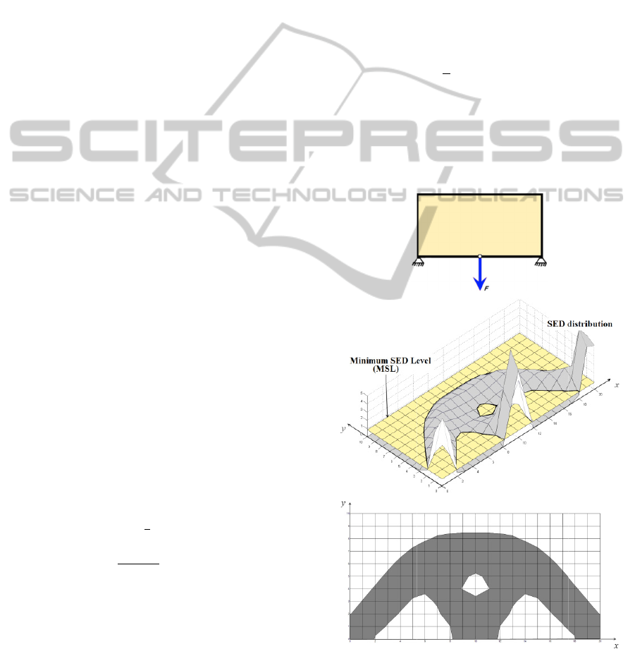
(a)
u
re 1: a- I
n
d
itions. b-
S
rsection of cr
i
a
l solution sho
w
d
ered as a
d
d
the distribu
t
considered a
s
v
e used strai
n
for finding
i
n the design
d
w
ill be gradu
a
s
and added t
o
utiona
r
y pro
c
r
ial can be a
c
operty to low
r
ain energy d
d
fro
m
=
1
2
m
ent displace
m
matrix whic
h
T
opolo
gy
O
n
itial design
d
S
tructural bo
u
i
teria (SED) d
i
w
n in a fixed g
r
d
esign variab
l
u
tion of mate
r
s
a design v
a
n
energy dens
i
the efficient
domain. The
r
a
lly removed
o
the high SE
D
cedure. The
c
hieved by a
s
w
SED region
s
d
ensity of the
/
m
ent vector a
n
h
is calculate
d
O
ptimizati
o
d
omain with
u
ndary repre
s
d
istribution an
d
r
id domain.
l
e, in our
r
ial inside
a
riable. In
i
ty (SED)
material
r
efore, the
from the
D
regions
effective
s
signing a
(sof
t
-kill
elements
(3)
n
d
the
d
using an
o
n
boundary
s
ented by
d
MSL. c-
X-FEMbasedTopologicalOptimizationMethod
467

The basic idea of isoline design is to represent the
shape and topology of the structure using the
contours of desired structural behaviour. This idea
has been suggested in several studies (Maute and
Ramm, 1995); (Lee et al., 2007). The isoline
optimization algorithm that we use in this paper is
originated from the isoline topology design (ITD)
algorithm proposed by Victoria et al., 2009.
The ITD approach can be summarized into the
following steps:
1- An extended finite element analysis is performed
to find the distribution of strain energy density
within the design domain.
2- A minimum SED level (MSL) is determined and
the new structural boundary is obtained from
intersection of SED distribution and MSL.
3- The regions of the domain having the criteria
level less than MSL are not included in the design
domain. Therefore their material property is set to
the weak material. The regions where the criteria
level is more than MSL are inside the design domain
and their material property is set to the solid
material.
4- Steps 1-3 are repeated by gradually increasing
the MSL until a desired optimum is obtained.
2.2.1 Integration Scheme
In a conventional fixed grid approach, the stiffness
matrices of the boundary elements are approximated
by a density scheme in which the stiffness of an
element is proportional to the area ratio of the solid
part of the element. The material is considered to be
uniformly distributed through the whole element and
the variations in material distribution in an element
are not taken into account in calculating the element
stiffness matrix. For example, figure 2 shows three
different shapes for a boundary element where the
area fraction of solid material within the element is
0.50. Using density method the same stiffness is
calculated for all three elements. This issue may
cause errors near the boundary of the design during
the optimization process.
(a)
(b)
Figure 2: a- Typical boundary elements for area
ratio=0.50. b- Their density scheme equivalent solid
element with 50% density.
The extended finite element method (X-FEM) is
an alternative fixed grid approach proposed by Moës
et al in 1999. It was originally developed to
represent crack growth in a fixed grid domain
without meshing the internal boundaries. X-FEM
has also been implemented for other kinds of
discontinuities such as fluid structure interaction
(Gerstenberger and Wall 2008) and modelling holes
and inclusions (Sukumar et al 2001). In our case, the
X-FEM scheme for modelling holes and inclusions
can be implemented for modelling the boundary of
the design (weak/solid material interfaces) during
the optimization process. In this approach, the
displacement field is approximated by the following
equation:
=
(4)
where
are the classical shape functions associated
to degree of freedom
, and the Heaviside function
H(x) has the following properties:
=
1∈Ω
0∉Ω
(5)
where Ω
is the solid sub-domain. Since there is no
enrichment in the displacement approximation
equation of X-FEM in modelling holes and
inclusions, there will be no augmented degrees of
freedom during optimization. Equation 5 defines a
zero displacement field for the void part of the
element, which means that only the solid part of the
element contributes to the element stiffness matrix.
Thus we can use the same displacement function as
FEM and simply remove the integral in the void sub-
domain of the element.
=
Ω
Ω
(6)
with the displacement differentiation matrix,
the elasticity matrix for the solid material and t the
thickness of the element. When an element is cut by
the boundary, the remaining solid sub-domain is no
longer the reference rectangular element. So we
partition the solid part of the boundary element into
several sub-triangles (figure 3) and use Gauss
quadrature to calculate the integral given by
equation 6.
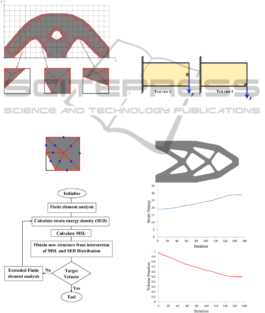
2.2.2 Combining X-FEM and the
Optimization Algorithm
Figure 5 illustrates the topology optimization
procedure used which in general consists of
initialization, X-FEM structural analysis, and isoline
SIMULTECH2012-2ndInternationalConferenceonSimulationandModelingMethodologies,Technologiesand
Applications
468
update scheme. In initialization, the initial material
distribution within the design domain and the
descretization of the design domain, as well as the
necessary parameters for the isoline topology design
are defined.
Figure 3: The solid sub-domain of the boundary elements
are partitioned into several sub-triangles.
In our study, the second order Gauss rule with 3
midline Gauss points was implemented (figure 4).
Figure 4: X-FEM integration scheme.
Figure 5: Flowchart of optimization algorithm.
In the X-FEM structural analysis, by using nodal
criteria numbers, the elements are categorized into
three groups: solid, void and boundary elements.
Solid and void elements are treated using classical
finite element approximation. The stiffness matrix of
the boundary elements are calculated by partitioning
the solid sob-domain into several sub-triangles and
applying the Gauss quadrature integration scheme
described in the previous section.
The minimum SED level (MSL) is calculated by
increasing the value from the last iteration. The new
structure is obtained from the intersection of the
MSL and current criteria distribution. The process is
continued until the target volume is achieved.
Figure 6: The two test cases.
3 TEST CASES
Figure 7: Optimized final design and iteration histories of
objective function and volume fraction for test case 1.
X-FEMbasedTopologicalOptimizationMethod
469
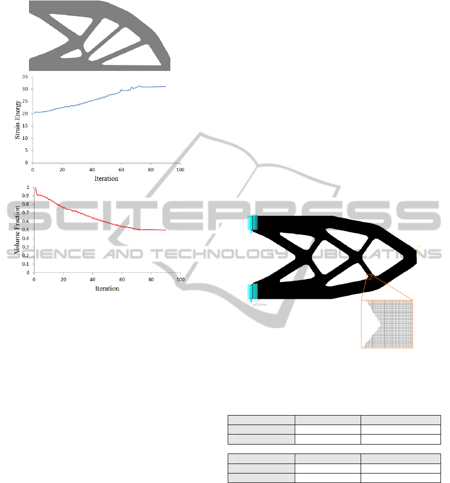
Figure 8: Optimized final design and iteration histories of
objective function and volume fraction for test case 2.
The proposed method of combining X-FEM and
evolutionary optimization algorithm was
implemented in a MATLAB code to present the
topology optimization of 2D rectangular domains.
Two test cases are used in this study (figure 6). First
a short cantilever beam having length 60, height 30
and thickness 1 where a unit concentrated load is
applied in the middle of the free end. The second test
case was a cantilever beam having the same
dimensions as test case 1 but with the load applied at
the bottom of the free end. A 60x30 mesh was used
for both cases to discretize the design domain. To
avoid singularity issues with the concentrated
loading, the loading region was treated as a non-
design domain.
The optimized final design, as well as the
iteration histories of the objective function and
volume fraction for the test cases 1and 2, are shown
in figures 7 and 8, respectively. It can be seen that
the strain energy increases, as material is gradually
removed from the design domain, then reaches a
constant value at convergence.
3.1 A Methodology for Evaluating
X-FEM Solutions
To evaluate the performance of the final solutions
and the accuracy of the proposed method, the
obtained solutions were discretized by a very fine
structured mesh and imported to NASTRAN to
perform a classical finite element analysis (figure 9).
Table 1 compares the X-FEM solutions and the
regenerated NASTRAN structures in terms of their
strain energies and tip displacements. It can be seen
that the X-FEM solutions are very close to the
regenerated NASTRAN solutions. The slight
difference in the X-FEM and NASTRAN results
may be attributed to the different mesh size used in
the two approaches.
Figure 9: XFEM solution discritized by a very fine mesh
and imported to NASTRAN.
Table 1: Comparison of X-FEM solutions and regenerated
NASTRAN structures.
Test case 1 Strain Energy Tip Displacement
X-FEM 29.04 54.00
NASTRAN 29.21 54.39
Test case 2 Strain Energy Tip Displacement
X-FEM 31.08 57.54
NASTRAN 31.24 57.85
4 CONCLUSIONS
In this study, X-FEM and Isoline design are
implemented for the topology optimization of 2D
continuum structures. By applying the proposed X-
FEM scheme there is no need to use the time
consuming remeshing and moving mesh approaches
to improve the FE solution. The generated structures
have smooth boundaries which need no further
interpretation and post-processing. The numerical
SIMULTECH2012-2ndInternationalConferenceonSimulationandModelingMethodologies,Technologiesand
Applications
470

examples presented in this paper show the accuracy
and efficiency of the proposed algorithm.
ACKNOWLEDGEMENTS
The authors are grateful for the funding provided by
Loughborough University.
REFERENCES
Allaire, G., Jouve, F., Toader, A. M., 2004. Structural
optimisation using sensitivity analysis and a level set
method, J. Comp. Phys., 194, pp. 363–393.
Bendsøe, M. P. 1989. Optimal shape design as a material
distribution problem. Struct. Optim. 1, pp. 193–202.
Bendsøe, M. P. and Kikuchi, N., 1988. Generating optimal
topologies in structural design using a homogenization
method. Computer Methods in Applied Mechanics and
Engineering, 71, pp. 197-224
Dunning, P., Kim, H. A. and Mullineux, G., 2008. Error
analysis of fixed grid formulation for boundary based
structural optimisation. In: 7th ASMO UK / ISSMO
conference on Engineering Design Optimisation, 7-8
July 2008, Bath, UK.
Gerstenberger, A., Wall. W. A., 2008. An eXtended finite
element method/Lagrange multiplier based approach
for fluid-structure interaction. Computer Methods in
Applied Mechanics and Engineering, 197, pp.1699-
714.
Huang, X., Xie, Y. M., 2009. Evolutionary Topology
Optimisation of Continuum Structures, Wiley.
Lee, D., Park, S., Shin, S., 2007. Node-wise topological
shape optimum design for structural reinforced
modeling of Michell-type concrete deep beams. J
Solid Mech Mater Eng, 1(9), pp. 1085–96.
Maute, K., Ramm, E., 1995. Adaptive topology
optimisation. Struct Optim, 10, pp. 100–12.
Miegroet, L. V., Duysinx, P., 2007. Stress concentration
minimization of 2D filets using X-FEM and level set
description. Structural and Multidisciplinary
Optimisation, 33, pp. 425-38.
Querin, O. M., Steven, G. P. and Xie, Y. M., 1988.
Evolutionary structural optimisation (ESO) using a
bidirectional algorithm. Engineering Computations, 15
( 8), pp. 1031-1048.
Moës, N., Dolbow, J. and Belytschko, T., 1999. A finite
element method for crack growth without remeshing,
International Journal for Numerical Methods in
Engineering. 46, pp. 131–150.
Sigmund, O., 2001. A 99 line topology optimisation code
written in Matlab. Struct Multidiscipl Optim, 21, pp.
120–127.
Sukumar, N., Chopp, D. L., Moës, N. and Belytschko, T.,
2001. Modeling Holes and Inclusions by Level Sets in
the Extended Finite Element Method. Computer
Methods in Applied Mechanics and Engineering, 190,
pp. 6183–6200.
Victoria, M., Martı´, P., Querin, O. M., 2009. Topology
design of two-dimensional continuum structures using
isolines. Computer and Structures, 87, pp.101–109.
Victoria, M., Querin, O. M., Mart
ı´, P., 2010. Topology
design for multiple loading conditions of continuum
structures using isolines and isosurfaces. Finite
Elements in Analysis and Design, 46 , pp. 229–237.
Wang, M. Y., Wang, X., Guo, D., 2003. A level set
method for structural topology optimisation. Comput.
Meth .Appl. Eng., 192, pp.227-46.
Wei, P., Wang, M.Y., Xing, X., 2010. A study on X-FEM
in continuum structural optimization using level set
method. Computer-Aided Design, 42, pp. 708-719.
Xie, Y. M. and Steven, G. P., 1993. A simple evolutionary
procedure for structural optimization. Computers &
Structures, 49, pp. 885-896.
Yang, X. Y., Xie, Y. M., Steven, G. P., and Querin, O. M.,
1999. Bidirectional evolutionary method for stiffness
optimisation. AIAA J., 37(11), pp.1483–1488.
Zhou, M., Rozvany, G. I. N., 1991. The COG algorithm,
Part II: Topological, geometrical and general shape
optimisation. Comp. Meth. Appl. Mech. Eng., 89, pp.
309-336.
X-FEMbasedTopologicalOptimizationMethod
471
