
Optimizing Energy using Probabilistic Routing in Underwater
Sensor Network
Sanjay K. Dhurandher
1
, Mohammad S. Obaidat
2
, Abhishek Gupta
1
,
Prateek Gupta
1
and Siddharth Goel
1
1
CAITFS, Division of Information Technology, Netaji Subhas Institute of Technology, University of Delhi,
New Delhi, India
2
Department of Computer Science & Software Engineering, Monmouth University, New Jersey, U.S.A.
Keywords: Underwater Sensor Networks, Probabilistic Routing, Simulation Analysis, Performance Evaluation.
Abstract: As the Importance of Applications, Such as Ocean Sampling, Environmental Monitoring, Disaster
Prevention, and Distributed Tactical Surveillance, Has Recently Grown, the Need for Underwater
Communication Has Become More Pronounced. unlike Terrestrial Sensor Networks, Underwater Sensor
Networks (Uwsns) Have Different Characteristics Such as a Long Propagation Delay, a Narrow Bandwidth
and High Packet Loss.Considering the Various Challenges Posed by the Underwater Environment, a
Routing Algorithm Has Been Proposed in This Paper. the Algorithm Consists of Special Features, including
Three Different Types of Nodes in the Architecture Proposed, a Mathematical Formula in Order to Select
the next Node to Be Used for Transmission. the Major Aim of the Algorithm Is to Select the next Node to
Be Used for Successful Data Delivery, and Ensure Minimum Energy Consumption. the next Node Is
Chosen With Utmost Care in Order to Increase the Probability of Successful Data Delivery. the Packet Is
Transferred from the Source to the Sub-Destination by Exploiting Minimum Energy of the Nodes. the
Simulation Studies for the Protocol Were Conducted using AQUA-GLOMO Network Simulator. the
Protocol Was Benchmarked With DSR Routing Protocol. the Matrices That Were Considered for the
Simulation Study Were Throughput, PDR, Energy Consumption and Delay and It Was Observed That Our
Proposed Model Performed Better in the Underwater Environment.
1 INTRODUCTION
Marine life is constantly being exploited by humans.
Be it leakage of oil in sea waters while extracting
crude oil from sea beds, dumping of industrial
wastes or over fishing in a particular area. All these
and several other human activities disturb the habitat
of aquatic creatures. Since, one cannot afford more
contamination of water resources, it is the need of
the hour that there is continuous monitoring of the
underwater environment of seas and oceans and
reporting of undesirable activities taking place-
whether human or natural.
Acoustic underwater ad-hoc networks need
special attention, due to the uselessness of radio
waves in water. This gives way to large propagation
delays. The diverse topology accounts for
connection impairment, high bit error rate, frequent
temporary losses of connectivity, and loss of nodes
due to erratic water currents. All the above
mentioned points hinder us from developing a
routing algorithm that ensures high probability of
successful data delivery, minimum energy
expenditure and lesser time delays.
The transmission of data packets is done in a
hop-by-hop fashion. The major focus has been on
the selection of the best suited next transmission
node. This ensures efficient data delivery with
optimized energy consumption. A mathematical
model has also been proposed in order to achieve
this goal.
The selection of the next node is done on the
basis of the relative depth, and the energy and the
distance of the nearby neighbouring nodes. The
concept of VBR is also being applied in order to
incorporate the variable “distance” (distance
between sender nodes and other relaying nodes) in
the protocol.
409
Dhurandher S., Obaidat M., Gupta A., Gupta P. and Goel S..
Optimizing Energy using Probabilistic Routing in Underwater Sensor Network.
DOI: 10.5220/0004168004090416
In Proceedings of the 2nd International Conference on Simulation and Modeling Methodologies, Technologies and Applications (SIMULTECH-2012),
pages 409-416
ISBN: 978-989-8565-20-4
Copyright
c
2012 SCITEPRESS (Science and Technology Publications, Lda.)

The proposed algorithm is free of any table
maintenance or time synchronization techniques.
Hence, these features help in saving energy of the
nodes up to some extent.
2 RELATED WORK
Underwater environment poses many problems for
efficient routing in the underwater sensor networks.
The routing procedures proposed for terrestrial
sensor networks cannot be directly applied in the
underwater scenario. Acoustic wavesare used for
communication instead of radio waves which are
used in terrestrial sensor networks. Acoustic
wavesare better than radio waves in underwater
environment due to its much lower attenuation as
compared to radio waves in water. But acoustic
waves have their disadvantages as well. They are
characterized by low bandwidth, high propagation
delay and high bit error rate. Energy efficiency is the
major concern in underwater environment due to the
use of acoustic signals and harsh conditions in
underwater environment. This makes node
replacement a difficult task and also results in a very
unpredictable and dynamic topology of the network.
Recently, many routing protocols have been
proposed to accomplish effective routing in
underwater sensor networks in an energy efficient
way.
In VBF (Vector-Based Forwarding scheme) (Xie
et al., 2005), each of the sender nodes’ one hop
neighbour compete to be the next hop node of the
route towards thedestination. Each neighbour
computes its perpendicular distance from the virtual
vector between the sender and the destination. This
vector is known as the routing vector. A predefined
radius forms the routing pipe around the routing
vector. To be a candidate for next hop, a node must
lie in the routing pipe formed. Multiple candidates
compete among themselves to be the next relay node
using the desirableness factor, which tells each node
how long it must hold the packet before relaying it.
The desirableness factor favours the node nearest to
the destination. VBF has been extended to HH VBF
(Hop-by-HopVector-Based Forwarding scheme)
(Nicolaou et al., 2007) to overcome the
shortcomings in VBF such as small data delivery
ratio in sparse networks and sensitivity of the
routing radius. Instead of using a single routing pipe
between the source and the destination, HH VBF
uses routing pipes in a hop by hop fashion which
increases the packet delivery ratio.
Another location based routing procedure is the
DFR(Directional Flooding-based Routing) (Hwang
and Kim, 2008). In DFR packet transmission is
achieved through scope flooding. The flooding zone
is decided by the angles between FS vector and FD
vector, where F is the node that receives a packet
and S and D are source and destination respectively.
F decides whether to forward the packet or not by
comparing the SFD angle with the criterion angle
(Base angle) which is included in the received
packet.
In SBR-DLP (Chirdchoo et al., 2009) algorithm
the sender node tries to find the next suitable relay
node by broadcasting a check_ngb packet. All the
nodes that hear this packet respond by sending
check_ngb_reply to the sender. To reduce collisions
at the sender node each neighbour node determines
the sector in which it is in and then schedules the
sending of check_ngb_reply accordingly. The
transmission time of the check_ngb_reply depends
on the priority value associated with each sector.
Using the maximum possible relative velocity and
propagation delay associated with the transmission
of the check_ngb_reply packet the sender node
filters out those nodes that may travel out of its
range before being able to acknowledge the receipt
of the packet. This algorithm takes into account the
node mobility in undersea environments but the
overhead associated with the generation and
processing of mobility (velocity) information of the
relaying nodes along with the location information is
quite large and is not suitable in underwater
environments.
All the above mentioned solutions make use of
the location information of the nodes using the GPS.
Use of GPSand the overhead due to the location
information generated involves large energy
consumption. A significant amount of node energyis
consumed in finding its current location using the
GPS system periodically.
In DUCS (Distributed Underwater Clustering
Scheme) (Domingo and Prior, 2007), a GPS free
scheme, the nodes organize themselves into local
clusters and one node is selected as cluster head for
each cluster. Each node in the cluster transmits its
data to the cluster head and cluster head transmits it
to the sink via the relays of other cluster heads.
Cluster Head selection mechanism has a large
overhead associated with it and is not energy
efficient. Also, there will be collisions at cluster
head when the cluster members send their data.
SIMULTECH 2012 - 2nd International Conference on Simulation and Modeling Methodologies, Technologies and
Applications
410

Another GPS free scheme for underwater sensor
networks is E-ITRC (Energy efficiency &
Innovative Time Reduction Communication)
protocol (Donghoon et al., 2007), which is based on
minimum response time between the surface station
and the underwater sink node. That is, the fastest
packet arrival time to a surface station from an
underwater sink node is the standard to select routers
among underwater relay nodes. This method also
lacks energy efficiency as the node selection
mechanism requires a large number of
transmissions. This algorithm has an on demand
element associated with it. On demand routing
protocols are not suitable in underwater
environments due to high node mobility and
dynamic topology of underwater networks.
3 PROPOSED MODEL
A. Assumptions
Basically, we have two assumptions in this work.
-General Information
All nodes know their depth, their remaining energy
and the quality of the link with their neighbors.
-Link Quality
All nodes can measure each link quality among
neighbors.
B. Protocol Description
Types of nodes to be used:
1. Relaying nodes.
2. Sensor nodes deployed at the sea bed.
3. Floating nodes (the receivers).
4. Special underwater nodes (Dhurandher et al.,
2008).
Relaying Nodes - These are the data forwarders and
do the simple relaying function. These simply float
underwater in the water column between the sensor
and the floating receiver nodes .They Communicate
using the acoustic channel.
Sensor Nodes - These are deployed at the seabed and
are the data generators. These nodes perform the
function of gathering information from the sea bed.
They communicate with the relaying nodes using the
acoustic channel.
Floating Nodes - These are deployed at the sea
surface and are the data collectors. These are the
destination nodes for the data generated at the sea
bed in the sensor nodes. While communicating with
another floating receivers these use radio waves and
acoustic waves for communication with the relaying
nodes.
Special Nodes(Dhurandher et al., 2008) - These are
deployed along with the relaying nodes but are less
in number as compared to them. Their function is to
do all the processing on behalf of the relaying nodes
regarding the selection of the next hop for data
transmission. These have much more battery life
than there laying nodes. They can deploy themselves
according to pressure and come to surface when
their power is low (Dhurandher et al., 2008) and
hence are easy to replace.
Now our basic aim is to make acoustic routing more
energy efficient, robust and efficient. To achieve the
above we propose the following:
• There should be no on demand element in the
routing protocol. We don’t have any route
request and route reply phases in our routing as
these are not desirable in highly dynamic
underwater environments.
• Special nodes are deployed along with the
underwater relaying nodes which do the
processing involved in the selection of the next
hop on behalf of the relaying nodes.
• The parameters used for the selection of next
node are depths of the neighbour nodes, their
respective energies and the route quality between
them after assigning each parameter proper
weight age.
Figure 1: The architecture of the proposed model
(Dhurandher et al., 2011).
The next hop candidate nodes must lie in a
virtual routing pipe of some predefined radius as
decided by the special node and centered around
it. This filters out those nodes that have the
possibility of travelling out of the range of the
sender node before the sender is able to
acknowledge the receipt of the packet.
Due to dynamic topology and node mobility due
to the undersea currents we are bound to have
link failures .To counter these and to achieve a
near 100% data delivery, we have designed an
efficient acknowledgement process. If the
acknowledgement for a particular packet
transmitted is not received in specific amount of
Optimizing Energy using Probabilistic Routing in Underwater Sensor Network
411
time then another transmission of the same
packet is tried forwarding it to another node.
This gives the element of multiple routing in our
scheme.
Multiple routing is done on the basis of priority
of the information as decided by the sensor
nodes.
The following packets are used in the protocol:
Request_next_nodepacket (request packet to
get the address of the next node)–The nodes on
receiving this packet will shift them to the
active mode. It will also contain the depth and
energy of the node.
Info_node packet (contains the node’s
information)– This packet will contain the data
about the depth and energy of the relaying
node sending it.
Data_packet (contains the information that is
to be transferred) – The data that is to be
transferred is contained in this packet.
Transmission_confirmed packet- Acts as a
message to the sender node that the
transmission has been done successfully and it
can delete the data.
C. Algorithm
Step 1: Information (inf) is being collected by the
sensor node. On the basis of the importance of the
information the sensor node assigns a priority level
to the data (pri). Node containing the data transmits
request_next_node packet (request packet to get the
address of the next node). Relaying nodes in the
transmission area and the nearest special node
receive the request_next_node signal. The Special
Node on receiving this packet will send a packet to
each node that it is the node acting on behalf of the
sender node.
Step 2: The relaying nodes which hear the signal and
are above the depth of node transmitting the
request_next_node packet send info_node packet
(contains the information about the depth and energy
of the node) to the special node.
Step 3: A virtual pipe is created by the special node
whose radius depends onk (number of relaying
nodes sending the info_node packet to the special
node) and depth of the special node from the surface
due to currents. The nodes lying outside this virtual
pipe are eliminated (i.e. not considered for
transmission).
Step 4: The route quality (RQ)of the remaining
relaying nodes is calculated on the basis of the
formula. Now this RQ is compared for the relaying
nodes and the best node(R) is calculated by this
method for further transmission. The data_packet
(the packet containing the information) is now
transferred to the selected relaying node(R). The
special node will now shift to promiscuous mode.
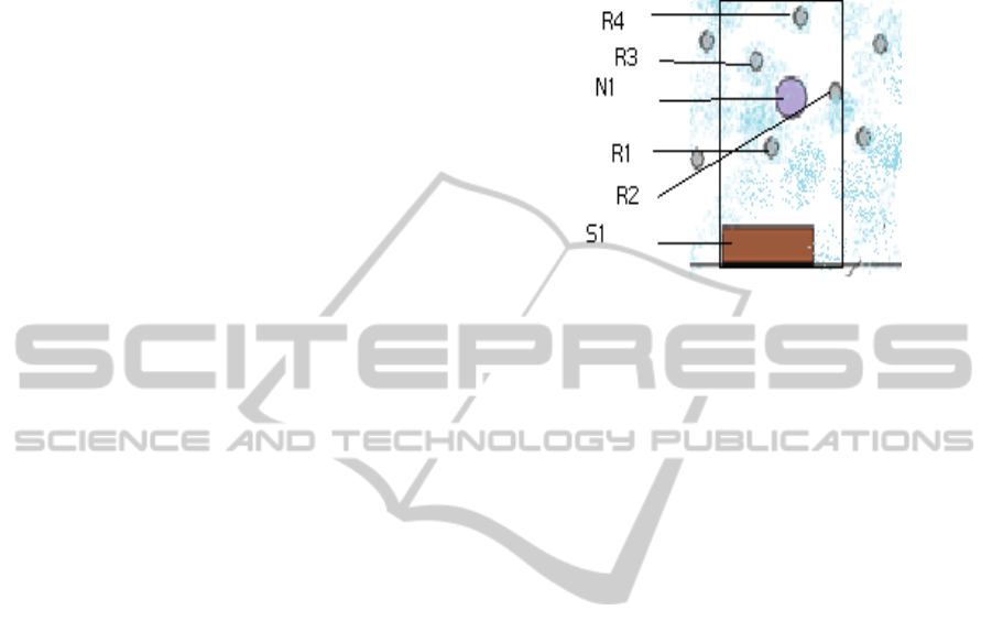
S – Source Node, N – Special Node, R – Relaying Nodes.
Figure 2: The construction of the virtual pipe to eliminate
the nodes lying outside it.
Step 5: Thebest node(R) will now transmit
request_next_node packet which will be heard by
the special node that was involved in its
selection .This acts as acknowledgement (ack) for
the delivered data_packet. If the acknowledgement
(ack) is not received up to a certain time limit then
depending on the priority (pri) of the information
(inf) the algorithm will either repeat itself by making
S1 select the second best node or the data_packet
will be dropped.
Step 6: Steps 1 to 5 will be repeated until the data is
received by the floating receiver node. In order to
remove ambiguity when two special nodes act on
behalf of sender node they first send a packet to
sender node asking for confirmation. If the sender
node receives one such request then it does not send
any packet to the special node. Otherwise, it sends a
packet to the node that is farther than the sender
node asking it not further transmit any packet. The
special node will wait for some time before sending
the packet that it is acting on the sender’s behalf. If
it receives no packet for a time it transmits the
packet assuming it has to act. Else, if it receives a
packet it will shift to promiscuous mode.
This is the basic pseudo code of the routing
protocol. It has the following terminologies:-
inf(information),pri(priority level to the
data),request_next_node packet(request packet to get
the address of the next node), info_node packet
(contains the information about the depth and energy
of the node), transmission_confirmed packet(Acts as
a message to the sender node that the transmission
has been done successfully and it can delete the
data), k (number of relaying nodes sending the
SIMULTECH 2012 - 2nd International Conference on Simulation and Modeling Methodologies, Technologies and
Applications
412

info_node packet to the special node),RQ (route
quality), R(best node), promiscuous mode(where the
node can only listen),ack (acknowledgement), ptr (is
a pointer variable that stores the address of the
current node).
Each node stores its own depth and energy (refer
subsection A of section III). The special nodes in
addition to this store the route quality (RQ[r] based
on the previous transmissions) between the nodes
lying in its transmission area. Information (inf) is
being gathered by sensor nodes. After a certain
period of time routing procedure initiates. Figure 3
contains the pseudo code which explains the
working of the algorithm.
4 PERFORMANCE
EVALUATION USING
SIMULATION ANALYSIS
To compare the routing protocol, and in order to
replicate the underwater environment, acoustic
communication based AQUA-GLOMO (Dhurandher
et al., 2012) simulation tool for underwater
networks, is used. AQUA-GLOMO is a simulation
tool based on Glomosim for large wireless networks
in the underwater scenario. Dynamic Source Routing
(DSR) (Johnson et al., 2001) protocol is taken as
benchmark and the results are compared to it
A. Simulation Setup
We focused on three performance measurements to
compare the routing protocol: Packet Delivery Rate
(PDR), Energy consumed by the network and
average end-to-end delay for a packet. The
comparison has been done for both static and mobile
scenarios, with and without the acknowledgement
process.
The three parameters in the experiments are defined
as follows:
I.) Packet Delivery Rate: Packet delivery rate is the
ratio of the number of user packets successfully
delivered to a destination to the total number of user
packets transmitted by source nodes.
II.) End-to-end Delay: The average time from the
beginning of a packet transmission at a source node
until packet delivery to a destination node. The time
when the last packet is delivered is recorded. The
average end-to-end delay is found by dividing the
above recorded time by the number of packets
received.
III.) Energy Consumed: The total energy consumed
by the network in transferring 100 packets from
source to the
Priority (pri) of the information (inf) is calculated by the
sensor node.
Do(while ptr!= address of the floating node)
Let the node which has data be A.
Declare ptr = address of A.
Request_next_node packet is transmitted by node A.
Relaying nodes in the transmission area and the nearest
special node (S1) receive the request_next_node
packet.
The relaying node which receives the
request_next_node packet and are above the depth d of
the node having the inf. (i.e. A) send info_node packet
to the special node (S1).
Now the virtual pipe is created whose radius depends
on k and height of S1 from the surface (it is taken due
to the effect of current).
R = Tr/k + s. (H – H
n1
) + D
n1-s1
(1)
R: Radius of the virtual pipe
Tr: Transmission radius of the nodes involved.
H: Depth of the sea bed
Hn1: Depth of node n1
S: Constant factor which brings down the value of H
comparable to Tr
The nodes outside this virtual pipe are not considered
for transmission. The nodes left after this elimination
are (r1, r2,……..rk).
Declare depth of each node as d[k] and energy of each
node as E[k]in the memory of the special node (S1).
The route quality (RQ[r]) between each two node is
already stored in the special node S1.
Quality of each node Q is calculated for the selection of
the best node depending on the formula:-
P[r] =
n
C
k
p
r
k
q
r
n-k
(2)
p
r
= {[(dep
r
)
a
. (en
r
)
b
] / summation of[(dep
r
)
a
. (en
r
)
b
]}
p
r
: probability of selection of relaying node r in one
trial.
Q
r
= (1-p
r
)
P[r]: probability that a particular node will be
selected exactly k times in n trials.
Q[r] = m.P[r] + n.RQ[r] (3)
Q[k] of each node is calculated.
Best node is calculated by comparing Q[k] let it be R.
S1 unicasts the next_node packet containing the
address of R to A.
Declare i=0.
Do While(i!=pri)
Node transmits data_packet.
If(S1 receives a request_next_node packet from R in
time<=t_timeout)
S1 transmits transmission_confirmed to A.
A deletes the data.
Break. [End of if structure]
Else
S1 transmits next_node packet having the address of
next best node to A.
i++ [End of inner while]
ptr=R [End of outer while]
Figure 3: The Pseudo Code.
Optimizing Energy using Probabilistic Routing in Underwater Sensor Network
413

destination. We have considered that the nodes
consume 1J of energy in transmitting data packets,
broadcasting Hello Packets, sending Loc and Ack
packets. It is also assumed that 0.5J of energy is
consumed by a node in doing calculations such as
calculating distance, updating table, etc.
In the analysis, one hundred (100) packets of 512
bytes each were sent from source to destination at a
time interval of 480ms.
B. Simulation Results
The simulation has been carried out in both static
and mobile scenarios.
Static Scenario
The terrain dimension was fixed to 900m x 900m.
The placement of the nodes was uniform and the
transmission power of each node was set to 3dB. All
the nodes were fixed at their respective locations.
Values for the three above mentioned performance
metrics were noted and the graph is plotted for81,
100, 169, 256, and 289 nodes. For each number of
nodes, the measurements are done with and without
the acknowledgement.
Figure 4: PDR vs. number of nodes in static scenario.
Figure 4 shows the metric PDR for the two protocols
DSR and Probabilistic Routing algorithm. In static
scenario almost all the packets are received at the
destination nodes in both cases. Hence, PDR has a
value of almost 1.0 for both the protocols.
Figure 5 shows the total energy consumed in the
network in transmitting 100 packets from source
node to destination node. It is clearly visible from
the figure that the energy consumption in PR is
much less than DSR. As the PDR is almost 1.0 for
the PR without Ackso there will be almost no
difference between the energy consumed for the
with and without Ackalgorithm as no packets will be
retransmitted.
Figure 5: Total Energy consumed in the whole network vs.
the total Number of Nodes present in the network for static
scenario.
Mobile Scenario
The results have been taken after the mobility of the
simulation is set to 2.0 m/sec.
Figure 6 shows the PDR in the mobile scenario. The
difference between DSR and PR algorithm is quite
remarkable and also when the Ack process is used
the PDR can further be improved.
Figure 6: PDR vs. number of nodes when nodes are
moving at a speed of 2 m/sec.
Figure 7: Total Energy consumed in the whole network vs.
the total Number of Nodes present in the network for static
scenario.
SIMULTECH 2012 - 2nd International Conference on Simulation and Modeling Methodologies, Technologies and
Applications
414

Figure 7 shows the total energy consumed by the
network in mobile scenario for 100 packets it can be
clearly seen that the energy used by PR is almost
half to that used by the DSR. Also in the case of PR
with acksome packets are retransmitted depending
on their priority due to quite a difference in PDR and
hence there is a small increase in the energy
consumed as compared to PR without ack though it
is still very less as compared to DSR.
Figure 8: Avg. End to end delay vs. the total Number of
Nodes.
In Figure 8, end to end delay of the PR is recorded
for the underwater environment and is compared
with DSR. As it can be clearly seen from the graph
for small number of nodes the end to end delay is
almost same for the PR and DSR but as the number
of nodes is increased the end to end delay of PR
turns out to be almost half to that of DSR.
5 CONCLUSIONS
In this paper we have proposed a Probabilistic
Routing algorithm which is suitable for mobile
underwater acoustic sensor networks where the
nodes can move along in the network.Its design
takes into consideration the unique characteristics of
such networks, namely, long propagation delay,
node mobility, high channel error rate, and low data
rate.
The DSR protocol has been implemented and
compared with the PR protocol. It is found that the
PR has a better performance with respect to energy
consumption, end to end delay and throughput as
compared to DSR in UWSN. From the simulation
results it is concluded that the lifetime and packet
delivery ratio of the network is improved, with the
reduction in end to end delay for the proposed
protocol over the existing DSR protocol.
The algorithm also ensures quite high PDR with
low energy utilization and does not involve any
multi-path routing or time-synchronization
techniques. The PR algorithm is simple and easy to
implement. Hence, the algorithm is suitable for real-
time implementation as well.
REFERENCES
M. Heissenbüttel and T. Bruan, “BLR: beacon-less routing
algorithms for mobile ad hoc networks,” Computer
communications, vol. 27, no. 11, pp. 1076–1096,
2004.
P. Bose, P. Morin, I. Stojmenovic, and J. Urrutia,
“Routing with guaranteed delivery in ad hoc wireless
networks,” ACM/Baltzer Wireless networks, vol. 7,
no. 6, pp. 609–616, Nov. 2001.
Karp and H. T. Kung, “GPSR: Greedy perimeter stateless
routing for wireless networks,” in Proc. ACM
MOBICOM’00, Boston, USA, Aug.2000, pp.243–254.
Peng Xie, Jun-Hong Cui and Li Lao, “VBF: Vector-Based
Forwarding Protocol for Underwater Sensor
Networks”, In Proc. Of IFIP Networking, May 2005,
pp. 1216-1221.
Nicolas Nicolaou, Andrew See, Peng Xie, Jun-Hong Cui
and Dario Maggiorini, “Improving the Robustness of
Location-Based Routing for Underwater Sensor Net-
works”, In Proc. of Oceans 2007, June 2007, pp.1-6.
Daeyoup Hwang and Dongkyun Kim, “DFR: Directional
Flooding-Based Routing Protocol for Underwater
Sensor Networks”, OCEANS 2008 pp.1-7.
Nitthita Chirdchoo, Wee-Seng Soh and Kee Chaing Chua,
“Sector-based Routing with Destination Location
Prediction for Underwater Mobile Networks”,
International Conference on Advanced Information
Networking and Applications Workshops, 2009.
WAINA’09 pp 1148-1153.
Mari Carmen Domingo and Rui Prior, “Design and
Analysis of a GPS-free Routing Protocol for
Underwater Wireless Sensor Networks in Deep
Water”, International Conference on Sensor
Technologies and Applications, SensorComm 2007,
pp 215-220.
Donghoon Kim, Yong-Man Cho, Changhwa Kim,
Sangkyung Kim, Soo-Hyun Park and Tae-Won
Kang,“E-ITRC protocol with Long & Adjustable
range on Underwater Acoustic Sensor Network”
AINAW’07 pp 665-672.
Sanjay K. Dhurandher, Sudip Mishra, M. S. Obaidat,
Sushil Khairwal “UWSim: A Simulator for
Underwater Sensor Networks”, Transactions of the
Society for Modeling and Simulation International,
USA, Volume 84 Issue 7, pp. 327-338, July 2008.
M. Takai, L. Balaji, R. Ahuja, R. Bagrodia and M.Gerla,
“Glomosim: a scalable network simulation
environment”, Technical Report 990027, Department
of Computer Science, University of California, USA,
1999.
Optimizing Energy using Probabilistic Routing in Underwater Sensor Network
415

Sanjay K. Dhurandher, Mohammad S. Obaidat, Megha
Gupta “An acoustic communication based AQUA-
GLOMO simulator fir underwater networks” Human-
Centric Computing and Information Sciences,
Springer, March 2012
David B. Johnson, David A. Maltz, and Josh Broch.
“DSR: The Dynamic Source Routing Protocol for
Multi-Hop Wireless Ad Hoc Network” in Ad Hoc
Networking, edited by Charles E. Perkins, Chapter 5,
pp. 139-172, Addison-Wesley, 2001.
S. K. Dhurandher, M. S. Obaidat, S. Goel, A. Gupta
“Optimizing Energy through Parabola based Routing
in Underwater Sensor Networks”, IEEE GLOBECOM-
2011, pp. 1-5, 5-9 Dec. 2011.
SIMULTECH 2012 - 2nd International Conference on Simulation and Modeling Methodologies, Technologies and
Applications
416
