
A Novel Formalization Process for Use Case Maps
Yahia Menassel
1
and Farid Mokhati
2
1
Department of Mathematics and Computer Science, University of Tébessa, Algiers, Algeria
2
Department of Mathematics and Computer Science, University of Oum El Bouaghi, Oum El Bouaghi, Algeria
Keywords: UCM, Maude Strategy Language, Formal Specification, Translation.
Abstract: This paper presents a novel process for formalizing UCM notation as an executable formal specification
described in the Maude language Strategy, a recent extension of Maude. The main motivation of our work is
essentially to provide a sound and rigorous description of complex systems described by UCM, which can
help analysts, designers and developers, to automating their verification and validation processes and to
assuring their quality.
1 INTRODUCTION
Use Case Maps (UCM) (Buhr and Casselman, 1995)
is an integral part of User Requirements Notation
(URN) (ITU-T, 2003); (Amyot, 2003) standards
proposed to the International Telecommunication
Union-Telecommunication (ITU-T) for describing
functional requirements as causal scenarios. UCM
allows developers to model dynamic behavior of
systems where scenarios and structures may change
at run-time. For these reasons, UCM have
successfully been used for service-oriented,
concurrent, distributed, and reactive systems
(Mussbacher, 2007).
In recent years, some works are proposed in
order to deal with UCM formalization, validation
and testing, we cite among others (He et al., 2003);
(Hassine et al., 2005). Those works have
considerably forwarded the domain by proposing
novel strategies for improving complex systems
development process based on UCM notation.
Although the formalization of UCM notation is not
new problem, we present in this paper, a novel
process for formalizing UCM notation as an
executable formal specification described in Maude
Strategy language (Marti-
Oliet et al., 2009), a recent
extension of Maude. The main motivation of our
work is essentially to provide a sound and rigorous
description of complex systems described by UCM,
which can help analysts, designers and developers,
to automating their validation and verification
processes and to assuring their quality.
The proposed formalization process consists in a
preliminary specification phase of transformation of
UCM modeling elements into Maude-Strategy.
The remainder of this paper is organized as
follows. In Section 2 we give a summary of UCM
notation. Section 3 presents a brief introduction to
Maude Strategy language. In section 4 we present
the translation process we propose. We discuss in
section 5, our actual research, draw some
conclusions and give some future work directions.
2 OVERVIEW OF USE CASE
MAPS
Use Case Maps (UCM) is a semi-formal notation for
describing scenarios of a system. This notation is a
high level scenario based modeling technique that
can be used to specify functional requirements and
high-level designs for wide range of systems (Liu
and Yu, 2001).
UCM expressed by a simple visual notation
allow for an abstract description of scenarios in
terms of causal relationships between
responsibilities along paths allocated to a set of
structural elements (components) (Mussbacher,
2007).
UCM consists of one or more paths describing
the causal flow of behavior of a system.
Furthermore, behavioral aspects (scenario paths) are
superimposed over components which represent the
architectural structure of a system. UCM abstract
from the details of message exchange and
communication infrastructures while still showing
307
Menassel Y. and Mokhati F..
A Novel Formalization Process for Use Case Maps.
DOI: 10.5220/0004170603070310
In Proceedings of the International Conference on Knowledge Management and Information Sharing (KMIS-2012), pages 307-310
ISBN: 978-989-8565-31-0
Copyright
c
2012 SCITEPRESS (Science and Technology Publications, Lda.)

the interaction between architectural entities
(Mussbacher, 2007). UCM are integrated with goal
models described with the Goal-oriented
Requirement Language (GRL), allowing for the
seamless capture of stakeholders’ goals, rationale,
and alternative solutions to achieve such goals. The
solutions are reasoned about with GRL and their
behavior and structure described in more detail with
UCM (Mussbacher and Amyot, 2008).
3 MAUDE STARTEGY
LANGUAGE
Maude strategy language (Marti-Oliet et al., 2009), a
recent extension of Maude, introduces some regular
expression combinators: concatenation (;), union (|),
and iteration (E* for zero or more iterations and E+
for one or more iterations). Additionally, there is the
combinator orelse is a typical if-then-else. These
combinators can be used to control how rules are
applied to rewrite a term in an attempt to control the
non-determinism in the execution process. For more
detail see (Marti-Oliet et al., 2009).
4 TRANSLATING UCM TO
MAUDE-STRATEGY
In this section, we present our translation process in
order to give a formal semantics of UCM notation
using Maude’s strategy language.
Table 1 presents the description of each element
of the UCM notation and the corresponding formal
semantics.
5 CONCLUSIONS AND FUTURE
DIRECTIONS
In this paper, a novel formalization process is
proposed for formalizing UCM element modeling in
the Maude strategy language. The proposed process
consists in a preliminary specification phase of
transformation of UCM modeling elements into
Maude-Strategy.
Currently we are developing a formal framework
which is based on transformation rules presented in
Table 1 for translating complex systems functional
requirements described by UCM into a formal
specification written in the Maude strategy language.
The Maude language is supported by a tool, which
will allow us to validate the generated code by
simulation.
REFERENCES
Amyot, D., (2003) ‘Introduction to the User Requirements
Notation: Learning by Example’, Computer Networks,
Vol. 42(3), pp. 285-301.
Buhr, R. J. A. and Casselman, R. S. (1995) ‘Use Case
Maps for Object-Oriented Systems’, Prentice-Hall,
USA. http://www.UseCaseMaps.org/UseCaseMaps/pu
b/UCM_book95.pdf.
Hassine, J., Rilling, J. and Dssouli, R., (2005) ’An ASM
Operational Semantics for Use Case Maps’, In RE '05:
Proceedings of the 13th IEEE International
Conference on Requirements Engineering (RE'05),
IEEE Computer Society, Paris, p. 467-468.
He, Y., Amyot, D., and Williams, A. W. (2003)
‘Synthesizing SDL from Use Case Maps: An
experiment’, In Proc SDL 2003: System Design, 11th
International SDL Forum, Stuttgart, Germany, p. 117-
136.
ITU-T, (2003) ‘User Requirements Notation (URN) –
Language Requirements and Framework’, ITU-T
Recommendation Z.150. Geneva, Switzerland.
Liu L., and Yu E., (2001) ‘From Requirements to
Architectural Design - Using Goals and Scenarios’,
From Software Requirements to Architectures
Workshop (STRAW 2001).
Mussbacher G., (2007) ‘Evolving Use Case Maps as a
Scenario and Workflow Description Language’, 10th
Workshop on Requirements Engineering (WER'07),
Toronto, Canada, p. 56-67.
Mussbacher G., and Amyot D., (2008) ‘Assessing the
Applicability of Use Case Maps for Business Process
and Workflow Description’, 3rd Int. MCETECH
Conference on e-Technologies, p. 219-222.
Martı-Oliet N., Meseguer J., Verdejo A, (2009) ‘A
Rewriting Semantics for Maude Strategies’, Electronic
Notes in Theoretical Computer Science, vol. 238(3),
pp. 227–247.
KMIS2012-InternationalConferenceonKnowledgeManagementandInformationSharing
308
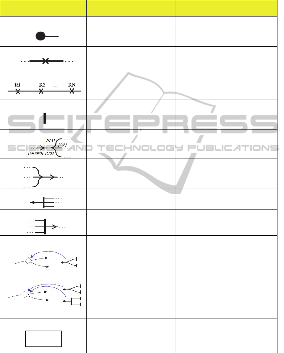
Table 1: Mapping from UCM specifications to Maude strategy.
Elements of the UCM notation Elements of the UCM description Maude Strategy Language
StartPoint
Begin of the path. Formally, a start point is
specified in terms of:
Preconditions that need to be satisfied to
enable the triggering of the path, and/or
A set of possible triggering events.
CRL
Start
:
Ed
1
… Ed
n
Conf
1
=> Conf
2
if Prec
1
… Prec
n
.
Responsibility
Sequenceofresponsibilities
A path describes a sequence of responsibilities
that need to be executed by system components
in response to a given triggering event.
Formally, a responsibility is defined in terms of:
A responsibility label, which gives a
textual description of the responsibility, and
A responsibility identifier, which allows
uniquely identifying a responsibility in a UCM
model.
RL
RespID
: Conf
1
=> Conf
2
.
strat sequence : @ Configuration .
sd sequence ≔ RL
1
; RL
2
; …; RL
N
.
EndPoint
End of the path. Formally, an end bar is
specified in terms of:
Postconditions that must hold after the
execution of the path, and
A set of possible resulting events.
CRL
End
:
Conf
1
=>Conf
2
Er
1
…Er
n
ifPstc
1
…Pstc
n
.
OR‐fork
Is used to show a point along a path where
alternative branches may be followed. Each
branch is associated with a distinct path segment.
strat OR
Fork
: @ Configuration .
sd OR
Fork
≔
RL
1
; ( CRL
2
orelse CRL
3
… orelse RL
N
) .
OR‐join
Captures the merge of two or more incoming
path segments into a single one without
requiring any synchronization or interaction
between the incoming path segments.
strat OR
Join
: @ Configuration .
sd OR
Join
≔
CRL
orelse CRL
…orelseRL
;RL
.
AND‐fork
Is used to illustrate a point along a path where a
single path segment forks into two or more
concurrent path segments.
strat AND
Fork
: @ Configuration .
sd AND
Fork
≔ RL
1
; (RL
2
|
…
|
RL
N
) .
AND‐join
Is used to illustrate a point along a path where
several concurrent path segments synchronize
together and result a single path segment.
strat AND
Join
: @ Configuration .
sd AND
Join
≔
RL
1
|
…
|
RL
N
; RL
N+1
.
StaticStub
Stub is a mechanism for path abstraction, hence
enabling hierarchical decomposition of complex
maps.
Static stub can contain only one plug-in.
(smod Static-Stub-NAME is
strats ORFork Plug-in Static-Stub: @ Configuration .
Plug-in := ORFork .
Static-Stub := Plug-in .
endsm)
DynamicStub
May contain several plug-ins, whose selection
can be determined at run-time according to a
selection policy (often described with pre-
conditions).
(smod Dynamic-Stub-NAME is
strats OR
Fork
AND
Fork
: @ Configuration .
strats Plug-in1 Plug-in2 Static-Stub: @ Configuration .
Plug-in1 := OR
Fork
.
Plug-in2 := AND
Fork
.
Dynamic-Stub := Plug-in1 orelse Plug-in2
.
endsm)
Component
A component is an object associated to a part of
system. The different tasks located inside a
component are performed only by this
component.
(omod Composant-NAME is
RL
1
.
…
RL
N
.
endom)
ANovelFormalizationProcessforUseCaseMaps
309
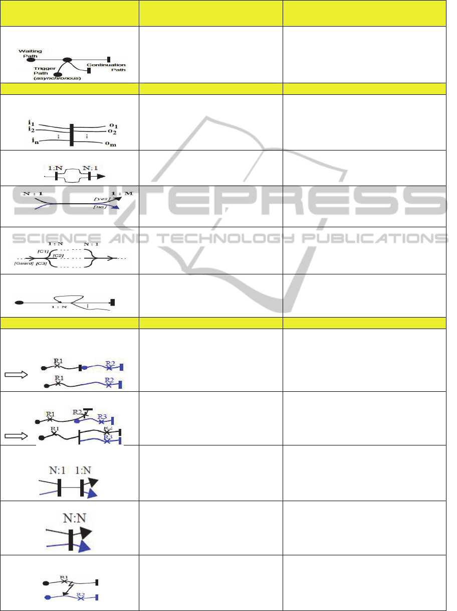
Table 1: Mapping from UCM specifications to Maude strategy (cont.).
Elements of the UCM notation Elements of the UCM description Maude Strategy Language
WaitingPlace
A Regular waiting place identifies a point along
the path at which the progression of a path is
blocked until a predefined unblocking (or
triggering) event occurs.
start Wait : @ Configuration .
sd Wait :=
WP
|
TP ) ; WaitPlace ; CP .
Special cases Special cases description Maude Strategy Language
GenericVersionofAND‐Join/Fork
Can be used to illustrate cases where an arbitrary
number, say N, of incoming path segments need
to synchronize together to trigger the execution
of an arbitrary number, say M, of outgoing path
segments.
start VG : @ Configuration .
sdVG ∶
RL
|
RL
|
…|RL
;RL
′
RL
′
…
RL
′
.
AND‐Fork/Join
AND-Fork with AND-Join.
start AND
ForkJoin
: @ Configuration .
sd AND
ForkJoin
≔AND
Fork
;RL
N+1
.
OR‐Join/fork
OR-Join with OR-Fork.
start OR
JoinFork
: @ Configuration .
sd OR
JoinFork
≔
OR
Join
;
CRL
1
'
orelse CRL
2
'
… orelse RL
M
'
.
OR‐Fork/join
OR-Fork with OR-Join.
start OR
ForkJoin
: @ Configuration .
sd OR
≔OR
;RL
.
Loop
Loop can be modeled implicitly with OR-fork
and OR-join.
start Loop : @ Configuration .
sdLoop ∶
CRL
orelse CRL
…orelseRL
.
UCM interactions Description Maude Strategy Language
Triggeraftercompletingpathexecution
is used to illustrate cases where the completion
of the execution of a path triggers another path
that is waiting on a waiting place. The waiting
can either be a start point or a waiting place
along a path.
start TAE : @ Configuration .
sd TAE := RL
1
; RL
2
.
Such as:
RL
1
: Conf
1
=> Conf
2
. RL
2
: Conf
3
=> Conf
4
.
and Conf
2
∩ Conf
3
≠ Ø
TriggerInPassing
is used to illustrate cases where a waiting place,
positioned either at the beginning (start point) or
along a path, is triggered by another path in an
asynchronous manner.
start TIP : @ Configuration .
sd TIP := AND
Fork
.
Rendezvous
This type of interactions is used to illustrate
cases where two, or more, paths synchronize
together to execute a certain path segment
(sequence of responsibilities) before returning to
the execution of their own respective path.
start RendezVous : @ Configuration .
sdRendezVous ≔ AND
;
RL
|
…
|
RL
.
Synchronize
This type of interactions is used to illustrate
cases where two, or more, paths synchronize
together and then return to the execution of their
own respective path.
startSynchronize:@Configuration.
sdSynchronize ≔
RL
|
…
|
RL
;
RL
|
…
|
RL
.
Abort
Is used to illustrate cases where the execution of
a path interrupts the execution of another. Top
path aborts bottom path after R1.
start Abort : @ Configuration .
sd Abor
t
≔
RL
|RL
.
Such as:
RL
1
: Conf
1
=> Conf
2
. RL
2
: Conf
3
=> Conf
4
.
and Conf
1
∩ Conf
3
≠ Ø
Waiting Place
KMIS2012-InternationalConferenceonKnowledgeManagementandInformationSharing
310
