
Assisted Software Exploration using Formal
Concept Analysis
Paul Heckmann and Daniel Speicher
Institute of Computer Science III, University of Bonn, Bonn, Germany
Abstract. Program comprehension requires understanding the structures within
the program. Some of these structures are created intentionally and well known
(design pattern), others arise implicitly but are still meaningful, and finally some
structures emerge accidentally without any meaning. We build on a previously
suggested approach to mine structures in software using Formal Concept Analy-
sis. In contrast to previous work, we found the performance of our tool to be still
acceptable for projects of interesting size (∼600 classes). A prominence index for
classes based on the formal concepts proved to be helpful for the identification of
core structures (high prominence) as well for focusing on specific structures (low
prominence). We report about two experiments. In the first the tool guided the
experimenter to central structures of JUnit as documented before but unknown
by the experimenter. In the second the tool led us to the core structures of our
own software.
1 Introduction
An object oriented software system essentially can be seen as a composition of struc-
tural concepts. Concepts in which classes and interfaces are connected with each other
using building mechanisms like abstraction, inheritance, and composition to realize a
certain functionality important to the respective part of the system. Some of these con-
cepts reoccur over the entire project and constitute to a programs unique character,
others reoccur yet only in certain parts suggesting core concepts of the program. Hence
revealing any of these structural concepts can be a first important step to understanding
the software itself, its character and its core functionality. But not all of these concepts
arise by design, e.g. by using design patterns as introduced by [6]. They may arise im-
plicitly and strongly depend on the developers style of solving a certain design problem.
In this work we propose an approach to mine structural concepts using a bi-clustering
technique called Formal Concept Analysis (FCA) [7], building on a previous approach
proposed by [11]. This technique allows us to group structures in source code into
meaningful groups without requiring any knowledge on the to-analyze program nor the
existence of a reference library of structures. We then improve this approach by the use
of a more efficient mining algorithm and extend it by adding filtering features that, on
one hand, allows us to interactively and iteratively explore the structures in a program,
and on the other hand supports us in finding those structural concepts constituting to its
core functionality.
In section 2 we give a brief introduction to the very basic idea of FCA. In section
Heckmann P. and Speicher D..
Assisted Software Exploration using Formal Concept Analysis.
DOI: 10.5220/0004175400110021
In Proceedings of the 3rd International Workshop on Software Knowledge (SKY-2012), pages 11-21
ISBN: 978-989-8565-32-7
Copyright
c
2012 SCITEPRESS (Science and Technology Publications, Lda.)

3 we reproduce the approach firstly introduced by [11] to apply FCA on our problem
of mining structures in source code. In section 4 we present our extensions to this ap-
proach. Finally, in section 5 we validate the performance improvement on three software
projects of different size and conduct two experiments to examine the practicability of
our extensions.
2 Formal Concept Analysis
Formal Concept Analysis (FCA) [7][3] is a branch of lattice theory that allows us to
identify meaningful groupings of objects G, i.e. quantities in a data set, that have com-
mon attributes M. In all the extent of this work, we are going to explain FCA on a very
simple yet illustrative example in which we pick a set of birds as G and a set of bird
characteristics as M and organize them in a so called formal context M, as depicted
in Table 1
1
. This formal context describes an incidence matrix in which M
(i,j)
= 1 if
object i has attribute j.
Table 1. FCA bird example context.
can fly can swim sings migratory monogamous
Ara × ×
Bluejay × × ×
Kiwi ×
Mallard × ×
Pelican × × ×
Using this context, FCA groups the objects and their attributes into formal concepts,
listed in Table 2. Such a formal concept consists of two sets, an extension and an in-
tension. The intension contains all common attributes that apply to the objects in the
extension. In the same way all objects contained in the extension share all properties
contained in the intension. Therefore a concept is a maximal collection of elements
sharing common properties. Adding an attribute to a concept’s intension there would be
at least one object in the extension that does not have this attribute. Adding an object to
the extension there would be at least one attribute in the intension this object does not
have. As a consequence the formal concepts build a complete partial order that can be
written as a lattice. Table 2 in some way suggests this order by the increasing number
objects and the decreasing number attributes from top to bottom.
2
3 FCA Application
3.1 Setup of the Formal Context
We apply FCA on an object oriented software system by considering structures between
1
It needs to be noted that ornithology usually is not part of our research. The data shown in
Table 1 may not be entirely correct.
2
In the context of this particular work, we are not making any use of this partial order.
12

Table 2. Formal concepts for the context in Table 1.
i Extension E
c
i
(↓) Intension I
c
i
(↑)
c
1
{Pelican} {can fly, can swim, migratory}
c
2
{Bluejay} {can fly, sings, monogamous}
c
3
{Ara, Bluejay} {can fly, monogamous}
c
4
{Mallard, Pelican} {can fly, can swim}
c
5
{Kiwi, Ara, Bluejay} {monogamous}
c
6
{Ara, Bluejay, Mallard, Pelican} {can fly}
classes and interfaces as the set G of FCA objects and class relationships that constitute
to a structure as the set M of FCA attributes. A first logical step hence will be to
define a structure model, i.e. the set of types of relationships we are looking for in a
system. For this, we adapt relationships from LePUS3 [5], a modeling language for
design patterns, and classify them into three structural and four behavioral relationship
types, as listed in Table 3. All relationships are orthogonal to each other. For instance,
the calls relationship between two classes A and B only applies if there is no forwards
relationship between A and B.
Table 3. Our set of relationships used to describe structures in source code.
Relationship r A class A is related to a class/interface B by r if
structural
has A has a one-to-one object association to B.
aggregates A has a one-to-many object association to B.
specializes A extends or implements B.
behavioral
calls a method in A calls a method in B.
forwards a method in A calls a method in B that shares
the same signature.
creates a method in A calls the constructor of a class and
binds the new instance to a variable of type B.
produces a non-private method in A creates a new instance
of B and returns it.
Using this model to describe structures, we then adopt the FCA approach introduced
by [11] and later improved by [1]. Here, having as input the set P of all classes in a
software and a fixed order n ∈ N we gather those class substructures that contain n
classes. Such a substructure can be described by two components, namely its n-tuple
of classes in P
n
(our FCA object) and a set of relationships between these classes (our
FCA attribute). We illustrate this approach by the example structure in Figure 1 with
P = {A, B, C, D, E} and n = 3. The corresponding formal context to Figure 1 is
shown in Table 4 while Table 5 lists the resulting formal concepts.
3.2 Iterative Concept Analysis
FCA generally is expensive. Its runtime increases exponentially by the set of objects,
the set of attributes and the density of the formal context. In order to reduce the set of
13

A
B C
D
E
Fig. 1. A simple class structure that could be an input to our FCA approach. It contains five classes
related to each other by two of our relationship types, has (simple association, diamond at source)
and specification (inheritance, triangle at target).
Table 4. Formal context for the structure in Figure 1 and n = 3. Four connected substructures
can be found. The attributes represent relationships and refer to the classes in the tuples by their
indexes. For instance, the attribute spec(2, 1) can be read as ”the element at index 2 specializes
the element at index 1”.
spec(2, 1) spec(3, 1) has(3, 1) has(2, 1) spec(3, 2) has(3, 2) has(1, 3) has(1, 2)
(A, B, C) × × ×
(A, B, D) × × ×
(A, C, D) × × × ×
(A, D, E) × × × ×
concepts computed by FCA as well as its expected runtime, we apply FCA iteratively.
In the first iteration, only the three structural relationships in Table 3 are considered,
creating concepts revealing the definition of a system part. In case we want to further
examine such a definition in its behavior, we apply FCA only on this part a second
time also considering our behavioral relationships but vastly reducing the set of FCA
objects.
3
3.3 Postprocessing
Removing Disconnected Structures. Due to the way we construct the formal context
basically two post-processing steps have to be taken. The first one is to remove concepts
whose intension describe a disconnected graph. In Table 5 concept c
5
represents such
a graph, as the nodes with the indexes 1 and 2 are connected with each other, the node
with index 3 is not connected to any of the other two.
Merging Equivalent Structures. For a context like ours FCA may produce concepts
that are basically equivalent and can be merged. That is the case if there exists a per-
mutation of the indexes of two concepts such that the intension of one concept can be
mapped into the other. For instance, in Table 5 concept c
1
is equivalent to c
2
by the
mapping 1 → 3, 2 → 1 and 3 → 2. To find such a mapping is a graph matching prob-
lem and hence not trivial. We used the VF2 algorithm proposed by [4] to accomplish
this task, however, since the graphs we are trying to match are relatively small a naive
depth-first search would work just as well.
3
The idea was already proposed by [11], with the difference that they used as attribute augmen-
tation the methods calling each other and their names.
14
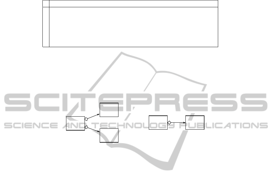
Table 5. Formal concepts for the context in Table 4.
i Extension E
c
i
(↓) Intension I
c
i
(↑)
c
1
{(A, D, E)} {has(1, 2), has(3, 2), spec(3, 2), has(2, 1)}
c
2
{(A, C, D)} {has(3, 1), has(2, 1), spec(2, 1), has(1, 3)}
c
3
{(A, B, C)} {spec(3, 1), has(3, 1), spec(2, 1)}
c
4
{(A, B, D), (A, C, D)} {has(1, 3), has(3, 1), spec(2, 1)}
c
5
{(A, D, E), (A, C, D)} {has(1, 2)}
c
6
{(A, B, D), (A, C, D), (A, B, C)} {spec(2, 1), has(3, 1)}
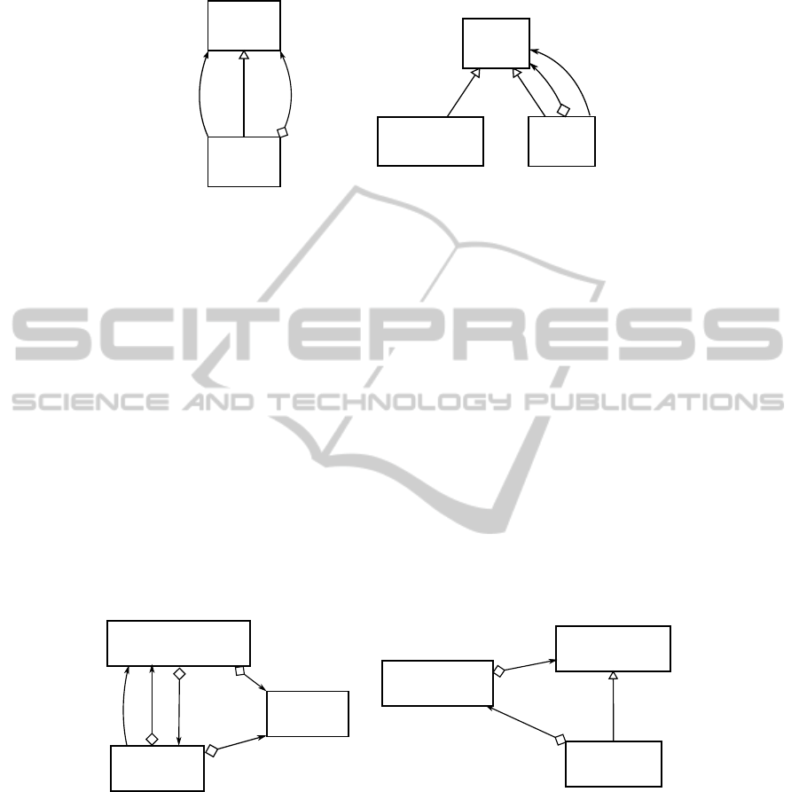
Removing Redundant Information. As an additional step we remove those concepts
that contain redundant information. This is the case if the structure the concept describes
contains a symmetric subgraph. A prominent example is the ”star pattern” as depicted
in Figure 2 (a). Here we can reduce the pattern to the one in Figure 2 (b) without losing
any information. Since the reduced concepts represent structures of a lower order, we
can ignore them.
A
A
B
C
B, C
(a) (b)
Extension:
(A, B, C)
Extension:
(A, B), (A, C)
Fig. 2. A ”star pattern” containing redundant information (a) and its reduction (b).
4 Filtering Features
4.1 Corner Elements
In order to dynamically change the space FCA is applied on we define the term Corner
Element. When gathering all substructures of given order in the setup of the formal
context we proceed inductively, i.e. first compute all structures of order n = 2, then
augment them to structures of order n = 3, etc.. Before starting an analysis run we can
declare classes as corner elements and aggregate them in a list. It is then guaranteed that
in the first inductive step each structure of order n = 2 consists of at least one element
from the corner element list. As a consequence, the structures serving as FCA objects
then are the union of all structures that evolve around the classes in our list of corner
elements.
4.2 Class Prominence
Taking a look at the extension of a formal concept we gain interesting information on
single classes. One of such is the prominence of a class. For the extension E
c
⊂ P
n
of
a formal concept c we can consider an index r ∈ {1, . . . , n} of the n-tuples in E
c
as a
15

role of concept c. A class p ∈ P in any of the n-tuples in G
c
at the index r then can be
seen as a role player of role r. The set of all role players for a role r in a concept c we
further refer to as P
c,r
. In Table 5, concept c
6
, we have three roles
4
according to their
indexes in the 3-tuples, played by the following classes: P
c
6
,1
= {A}, P
c
6
,2
= {B, C},
P
c
6
,3
= {D, C}.
Given a class p ∈ P and a role r in a concept c, we define its prominence u(p, r, c)
(3) in r simply as the scaled frequency η(p, r, c) (1) (2) of the class playing this role
multiplied by the size of E
c
.
η(p, r, c) =
|{e ∈ E
c
| e
r
= p}|
|E
c
|
(1)
φ(x) = x/(1 − x) (2)
u(p, r, c) = φ(η(p, r, c)) · |E
c
| (3)
In a final step we compute the absolute prominence u(p) (4) of a class p simply by
summing up the prominence values for a class over all roles over all concepts and
normalize the outcome over the absolute prominences of all classes.
u(p) =
X
c,r
u(p, r, c) (4)
Throughout the concepts listed in Table 5, apparently the class A is more prominent
than any of the other four classes. Pretending that we replace class A with another class
X in concepts c
1
-c
3
, class A would still gain the highest prominence value as it is the
only player of role r = 1 in concepts c
4
-c
6
, which all have a larger extension.
The prominence of a class can serve us in two ways: First, the more prominent a
class the higher the probability that it plays a role in a core concept of a software project.
One can see the prominence as a gravitation of a class. The higher, the greater is the part
of a software project that is ’attached’ to this class. Second, it could help us determining
appropriate corner elements as filters. The lower the prominence of a class, the smaller
the expected number computed concepts.
5 Case Studies
5.1 Our Tool
We implemented our approach as part of the Cultivate
5
plugin for the Eclipse
6
IDE.
Cultivate is a code analysis tool for Java programs. It in turn bases on the JTransformer
7
plugin which provides a Prolog factbase that represents the full abstract syntax tree of
the to-analyze Java program. Cultivate implements several program analyses written in
4
The number roles is determined by the order n.
5
http://sewiki.iai.uni-bonn.de/research/cultivate/start
6
http://www.eclipse.org/
7
http://sewiki.iai.uni-bonn.de/research/jtransformer/start
16

Prolog that are applied on this factbase.
To compute the formal concepts we use a relatively young algorithm proposed by [9].
This algorithm is particularly suitable to our approach compared to the algorithm [7]
used by previous works because it saves time not carrying the hierarchical order of the
concepts required to build the concept lattice. Due to our post-processing reorganizing
the computed concepts this additional information is useless to us anyway. Secondly,
this algorithm allows us to parallelize the computation, distributing the computational
load over several CPUs.
5.2 Data Set
We apply our tool on three different Java projects:
– JUnit
8
4.7, which is a testing framework for Java code of smaller size.
– Cultivate, the framework our tool is based on. It consists of a platform providing
utility classes and the engine on one hand and several addons on the other hand
that build upon this platform but not upon each other. As a consequence the overall
cohesion in this project is very low. Also we are familiar with its domain, which
makes it easier to evaluate our findings.
– JHotDraw
9
7, a free Java-based framework for creating graphical editors. In con-
trast to Cultivate we are not familiar with this project, yet enjoy it to be well doc-
umented. Also the overall cohesion of the project compared to Cultivate is fairly
high.
For the sake of simplicity we consider only the set of core classes (ignoring external
library classes) that fulfill the following requirements: The class neither is of a basic
type (Integer, Double, ...), an enumeration type nor an anonymous class.
5.3 Performance
We ran our analyses on an Intel Quad Core @2.83 GHz with 4 GB RAM under normal
load. Table 6 shows the runtime behavior we observed and number concepts computed
for each of the three sample projects and with regard to the order n. For n ≥ 5 on Cul-
tivate our tool failed due to lack of memory. This may or may not be caused by Prolog
and the fact it loads the entire factbase into the main memory as well as it caches its
Table 6. Observed runtime behavior of our tool in seconds and number concepts computed in the
first iteration.
JUnit 4.7 Cultivate JHotDraw 7
#classes 143 607 625
runtime concepts runtime concepts runtime concepts
n = 2 <1s 5 ∼2s 7 ∼3s 9
n = 3 <1s 16 ∼3s 45 ∼14s 38
n = 4 ∼1s 24 187s 154 130s 141
8
http://www.junit.org
9
http://sourceforge.net/projects/jhotdraw
17

query results. The reason why the analysis on JHotDraw is faster than on Cultivate for
n > 3 we ascribe to Cultivate being way less cohesive than JHotDraw, which eventu-
ally leads to a faster growth of concepts in n. Yet the actual number concepts in both
projects are insignificantly different what suggests a fairly large impact of our addi-
tional post-processing.
Recalling previous observations made by [1], using the Ganter algorithm [7] the analy-
sis of a sample project written in Smalltalk with 167 classes and n = 4 took approx. two
days.
10
Compared to this, our own results by far excel our expectations and prove this
technique to be a time-efficient way to analyze software projects even of larger scale.
6 Example Applications
6.1 Experiment 1: JUnit
In a first experiment we pick the smaller of our sample projects, JUnit, and let one of the
authors apply our tool on it with the goal to yield most relevant structures of the project
in at most five analysis steps. The project is well-documented and makes extended use
of design patterns, however, the experimenter neither is familiar with the project nor
with its documentation at the time of execution.
As a first step, the experimenter runs an analysis on structures of order n = 2. Despite
our expectations we found n = 2 particularly instructive, as its corresponding concepts
are small in number, easy to understand and most often already reveal those atomic
relationships between two classes larger patterns are only based on. The analysis com-
putes five concepts of which the one depicted in Figure 3 (a) catches the experimenters
attention as it is one of two with more than one relationship. This pattern suggests the
implementation of a tree structure using the Composite pattern [6]. In order to check
this presumption the experimenter runs an analysis on order n = 3 using the class
TestSuite as a corner element. Since this class has a significantly smaller promi-
nence than Test, it is more suitable as a filter. Two concepts are computed, one of
them actually representing the Composite pattern as depicted in Figure 3 (b).
As a specification of Test we find a class called TestDecorator in Figure 3 (b)
which suggests the implementation of the Decorator pattern [6]. Following the same
procedure as before (using TestDecorator as corner element) we can verify our
presumption.
Rechecking our findings so far with the JUnit documentation we can verify the com-
posite pattern instance as one most relevant to the base framework, while the decorator
pattern instance is particularly important to the extensional part which can be used by
developers to implement and plug in custom test definitions.
6.2 Experiment 2: Cultivate
In a second experiment we wanted to examine the precision of the prominence calcula-
tion and how it can be exploited to find core concepts in a software project. For this, we
10
A less advanced hardware may have an impact on these stats, too, considering the previous
observations date back eight years.
18
Test
TestSuite
TestCase
TestDecorator
JUnit4TestAdapter
JUnit4TestCaseFacade
*
forwards
Test
TestSuite
*
forwards
(a)
(b)
Fig. 3. Composite pattern candidate (a) and verified instance (b) in JUnit 4.7.
use our own project, Cultivate. Firstly, because we are familiar with it and can assess the
validity of the computed prominence values. Secondly, Cultivate basically is a platform
with a few core classes that, however, are extensively used by the add-ons that build on
the platform.
We run an analysis on structures of order n = 3 and retrieve the list of all occur-
ring classes ranked by their prominence. The one with the highest prominence value
is CultivateViewPart (∼12%), the next-prominent class is BaseQuery (∼3%).
In both cases we agree with the tool: CultivateViewPart is a class used as an
abstract view part that follows selections in the workbench and manages the subscrip-
tion of analyses on the corresponding software projects. It is basically inherited from all
add-on projects that provide a workbench view and in fact is one of the central classes
in Cultivate. BaseQuery is the abstract class to query analyses on Prolog side, spe-
cialized by 63 different classes inside the add-on parts.
We declare CultivateViewPart as corner element and run the analysis again. The
result is a set of 14 concepts of which two describe exactly the main responsibilities of
this class, depicted in Figure 4.
CultivateViewPart
ConfigurationQueriesModel
Repopsitory
creates
CultivateViewPart
IJavaSelectionListener
JavaSelectionService
*
(a) (b)
Fig. 4. Two core concepts of the Cultivate project. In Figure (a) the CultivateViewPart
creates and attaches to a ConfigurationQueriesModel object which then retrieves a
Repository for the currently selected project and handles query subscriptions on that repos-
itory. (b) describes an Observer pattern [6], in which CultivateViewPart is an observer,
JavaSelectionService handles workbench selections.
19

7 Discussion
We can see that FCA is a practical approach to mining structures in software projects
even of larger size. By not only considering the intension of each concept but also its
extension, we find a promising approach to assess the relevance and importance of cer-
tain classes of the software project. Having such an assessment we can exploit it either
as a clue to search and identify core concepts of the corresponding project or as an as-
sistance in choosing appropriate filter elements to narrow down the space the analysis
is applied on.
A very interesting observation we made during our studies on this technique is the im-
portance of structures of order n = 2. They are in many cases atomic components of
structural concepts such as design patterns that represent the core relationship the pat-
tern is based on. For instance, in the first experiment we started with the five structures
of order n = 2 and could easily detect a composite and a decorator pattern (as described
in 6.2) as well as Facade and a Chain Of Responsibility pattern [6].
Yet we think the overall number concepts computed with regard to the order n and
the size of our relationship model is too high to be convenient. On the other hand, reduc-
ing the set of relationships as FCA attributes lead to more abstract concepts, requiring
the user to more often investigate the source code in order to understand the context of
a concept. During our studies on this approach we found ourselves gaining preferences
on patterns over others, suggesting there can be defined heuristics about patterns be-
ing interesting and hence relevant or not. Given such heuristics one can impose further
structural constraints to extend the post-filtering.
8 Related Work
Formal Concept Analysis (FCA) was firstly proposed by [7] as a branch of lattice the-
ory. The first effort towards structure mining in source code using FCA was achieved
by [11]. Their approach then was later refined by [1] who reduced the number FCA
objects and hence improved the overall runtime. Further structure mining efforts for
object-oriented systems have been achieved by [12][8][2] who used subgraph matching
to group same structures formed by classes. We adopted the approach by [11] refined by
[1], enhanced the set of FCA attributes, i.e. class relationships, using a set of relation-
ships based on the modeling language LePUS3 by [5] and exchanged the previously
used algorithm to compute formal concepts by a relatively young algorithm that was
proposed by [9].
A slight connection to our findings of the importance of order 2 structures can be
drawn to [10], who tried to decompose design patterns into their elemental parts.
References
1. G. Ar
´
evalo. High Level Views in Object-Oriented Systems using Formal Concept Analysis.
PhD thesis, University of Bern, 2004.
2. A. Belderrar, S. Kpodjedo, Y.-G. Gu
´
eh
´
eneuc, G. Antoniol, and P. Galinier. Sub-graph Min-
ing: Identifying Micro-architextures in Evolving Object-oriented Software. Europ. Confer-
ence on Software Maintenance and Reengineering, 2011.
20

3. C. Carpineto and G. Romano. Concept Data Analysis, Theory and Applications. Wiley &
Sons, 2004.
4. L. P. Cordella, P. Foggia, C. Sansone, and M. Vento. An improved algorithm for matching
large graphs. In In: 3rd IAPR-TC15 Workshop on Graph-based Representations in Pattern
Recognition, Cuen, pages 149–159, 2001.
5. A. H. Eden, Y. Hirshfeld, and A. Yehudai. LePUS - A Declarative Pattern Specification
Language. Technical report, 1998.
6. E. Gamma, R. Helm, and R. Johnson. Design Patterns. Elements of Reusable Object-
Oriented Software. Addison-Wesley Longman, 1994.
7. B. Ganter and R. Wille. Formal Concept Analysis: Mathematical Foundations. Springer,
1998.
8. M. Gupta and A. Pande. Design patterns mining using subgraph isomorphism: Relational
view. International Journal of Software Engineering and Its Applications (IJSEIA), 2011.
9. P. Krajca, J. Outrata, and V. Vychodil. Parallel Recursive Algorithm for FCA. In Concept
Lattices and Their Applications (CLA), pages 71–82, 2008.
10. J. M. Smith and D. Stotts. Elemental Design Patterns: A Formal Semantics for Composition
of OO Software Architecture. In IEEE/NASA Software Engineering Workshop, pages 183–
190, 2002.
11. P. Tonella and G. Antoniol. Object Oriented Design Pattern Inference. In Proceedings of
ICSM, page 230ff. IEEE Computer Society Press, 1999.
12. Z.-X. Zhang, Q.-H. Li, and Ke-Rongben. A New Method for Design Pattern Mining. Inter-
national Conference on Machine Learning and Cybernetics, 2004.
21
