
From Business Services to IT Services by Capturing Design Decisions
Biljana Baji
´
c
1
, Claude Petitpierre
1
, Alain Wegmann
1
and Do Qaung Tri
2
1
Ecole Polytechnique F
´
ed
´
erale Lausanne (EPFL), CH-1015 Lausanne, Switzerland
2
Ho Chi Ming City University (HCMUT), District 10, Ho Cho Minh City, Vietnam
biljana.bajic@epfl.ch, claude.petitpierre@epfl.ch, alain.wegmann@epfl.ch,dotri84@gmail.com
Keywords:
Service Design, Service Science, Business-driven Development, Model Transformation.
Abstract:
The main goals of any service-oriented design include flexible support and adaptability of business services
and improved business-IT alignment. The existing approaches, however, have failed to fully meet these goals.
One of the major reasons for this deficiency is the gap that exists between how the computer science and
management science communities perceive the concept of service. We present a flexible, semi-automatic,
model-driven approach to designing IT services that directly satisfy business needs and requirements. We
begin with the design of business services and the capture of the design decisions that transform the business
design through multiple model layers to the IT service design. All layers can be simulated using the Alloy
Analyzer tool. The last layer can be run on a given target platform. This approach is demonstrated on the
running example based on the consulting project conducted at the company General Ressort. The central
aspect of our approach is separating the design decisions from anything that can be automated. It provides the
multi-perspective view of the system, by making the modeling process faster, leaving the designer the space
to focus on the design decisions and not on drawing the models.
1 INTRODUCTION
As there are many different definitions of services, we
give the one used in this paper. Based on (Blecher and
Sholler, 2009, p. 1), ”Business service is a business-
related work activity or duty performed for others to
produce a business outcome. It is the expectation of
the business person that the service will accomplish
this outcome. The person generally does not care how
it is accomplished, as long as it is done in an effective
manner from a business perspective.”
A business service may be supported by one or
more IT Service(s), and may consist almost entirely
of IT services, especially where these service are di-
rectly used by customer. Examples include online
banking and online shopping.
ITIL v.3 defines a IT service as ”a service pro-
vided to one or more customers, by an IT service
provider. An IT Service is based on the use of infor-
mation technology and supports the customer’s busi-
ness process. An IT Service is made up from a com-
bination of people, processes and technology.” (OGC,
2007)
Based on these definitions, we will explain our ap-
proach for transforming business services to IT ser-
vices.
The main goals of any service-oriented design in-
clude flexible support and adaptability of business ser-
vices and improved business-IT alignment, i.e. or-
chestration of the lower level IT infrastructure ser-
vices to deliver the desired business-level customer
services. The existing approaches, however, have
failed to fully meet these goals. One of the major rea-
sons for this deficiency is the gap that exists between
how the computer science and management science
communities perceive the services. In practice, the
business and technology perspectives of services have
to be considered separately. Even simple changes to
one perspective (e.g. due to new regulations or or-
ganizational change) require error-prone, manual re-
editing of the other one (Buchwals et al., 2011). Over
time, this leads to the degeneration and divergence of
the respective models and specifications; this thereby
aggravates maintenance and makes expensive refac-
toring inevitable.
Our approach for aligning business services with
IT services is flexible, semi-automatic, and model-
driven, enabling the implementation design of busi-
ness services. In the design process, the designer be-
gins by identifying the services required by the cus-
tomers, then follows by capturing the design deci-
sions. Based on these decisions, intermediate model
94
BajiÄ
˘
G B., Petitpierre C., Wegmann A. and Tri D.
From Business Services to IT Services by Capturing Design Decisions.
DOI: 10.5220/0004461500940104
In Proceedings of the Second International Symposium on Business Modeling and Software Design (BMSD 2012), pages 94-104
ISBN: 978-989-8565-26-6
Copyright
c
2012 by SCITEPRESS – Science and Technology Publications, Lda. All rights reserved

layers and finally IT services are generated. These
services are necessary for the implementation of the
application supporting the customer’s requirements.
This process allows business analysts to represent ser-
vices from a business point of view, while facilitating
the design and development of IT services.
The details embedded in an IT service design
model-layer enables the execution of the model on
the given target platform, such as JEE (Java Enter-
prise Edition). All the model layers can be translated
and simulated with the Alloy Analyzer tool (Jackson,
2011), so that the designer, by viewing a few instances
of the model, can see how each of the model layers
behave.
A central aspect of our method is that, in the ser-
vice design process design decisions are captured in
each step. This way, they are clearly separated from
the automatic part of the transformation. Thus, the
design process is done semi-automatically. In these
steps, the designer can independently make the deci-
sions about different aspects, influencing the service
design.
We illustrate our approach by the running example
based on a consulting project conducted at a company
that sells parts for watches in Switzerland, General
Ressort (GR).
We organize the paper as follows. In Section 2, we
explain our modeling method and outline the design
process. In Section 3, we discuss the simulation and
prototyping of the model layers. We present related
work in Section 4. The final section concludes the
study and discusses the future work.
2 MODELING THE
IMPLEMENTATION DESIGN
OF BUSINESS SERVICES AT
GENERAL RESSORT
For a better understanding of the design process, we
illustrate each design step by applying it to the exam-
ple of company GR. For the purpose of this paper, we
focus only on a simplified business service of order
processing. We illustrate the design steps in our ap-
proach based on this example. By convention, infor-
mation in italics are the corresponding names of the
elements in the model.
The simplified business service is executed as fol-
lows: ”GR gets order (OrderInitial) from the cus-
tomer that contains a unique customer name and
unique customer part id. The person dealing with
orders (OrderEntryPerson) receives the information
about the order (OrderInitial) and finds the customer
and the part by unique information in the enterprise
resource planning system (ERP). Finally, he creates
the confirmed order (OrderConfirmed) in the ERP.”
Notice that in the a real service, in case the cus-
tomer or the part is missing in the system, they are
created. However, as it does not show any new as-
pects of our approach, it is not shown in this paper.
2.1 Modeling Method
In order to understand the steps of our design process
and the example, we will explain the main principles
of the proposed modeling approach, mostly based on
Catalysis approach (D’Souza and Wills, 2001).
The central aspect of our approach is a system and
its two main aspects: organizational and functional
(Wegmann, 2003). For both aspects, we define the
black-box and the white-box view of the system. The
organizational black-box view of the system is called
’system as a whole’, and it hides the organizational as-
pects of the system; unlike the organizational white-
box view of the system, called ’system as a compos-
ite’, which reveals a system’s construction. Similarly,
the functional white-box view of the system is called
’action as composite’ and it provides insight into sys-
tem’s functionality, unlike the functional black-box
view (’action as a whole’) that hides them. This can
be seen in Figure 1.
There is also a special view of a system and a type
of the action, called ’action as n-ary relationship’,
where one action is distributed among many systems
connected with one action binding in between (Fig-
ure 2). In this way, it is specified what part of action
is in which system. However, the action parts are still
dependent on each other and cannot be treated sepa-
rately; only together can they be seen as one action.
Figure 1: Organizational and functional hierarchy.
Another important characteristic of our approach
is that it places the action on an equal footing with the
object, because good decoupled design requires care-
ful thought about what actions occur and what they
From Business Services to IT Services by Capturing Design Decisions
95

achieve. Therefore, behaviour and data are equally
important in the proposed method and each model
layer contains both the behaviour and data part of
the services.
2.1.1 Meta-model
In order to understand the models given in this paper,
we show the meta-model with relevant elements in
Figure 3. The full lines in the meta-model correspond
to the ’contain’ relationship, where one element is in-
side the other. The dashed lines correspond to the ’has
link to’ relationship, where one element is related to
the other with a line. The concepts used in the meta-
model are based on Catalysis terms. The table with
the corresponding business terms can be seen in Fig-
ure 4.
Figure 2: Action as n-ary relationship.
The root element of any model is WOC (working
object as composite), representing the system of in-
terest, in this case the market segment. It is compos-
ite, because it contains the main stakeholders, such as
the service provider (company providing the service)
and service consumer (customer company). WOC re-
veals the system structure, therefore it can contain
other WOs (whole and composite). It can also contain
actions shared among different systems (JA (joint ac-
tion) or SJAB (split joint action binding)). SJAB cor-
responds to the action binding in ’action as n-ary re-
lationship’, i.e. it connects several distributed actions
in different systems, thus making one action. JA is
the whole action with all its elements between many
systems. There are no action parts in the other sys-
tem. SJAB has links to SJAs (split joint actions). They
correspond to the action parts in ’action as n-ary re-
lationship’. One of them contains a link to the event,
showing who is initiating the action SJA
e
, while the
others have no event related to it SJA
ne
.
WOW does not reveal its structure. Therefore, it
does not contain other WOs. It can contain actions or
data elements (properties (LP), inputs (INP), outputs
(OUT) and EVENTs). These actions can be joint ac-
tions (SJA and JA) or localized (LA), meaning they
are inside just one WO, and are not split between
many WOs. As with all other whole-composite re-
lations, LAC (localized action composite) can have
many LAWs (localized action whole).
As a service is a duty performed for others pro-
ducing outcome, it always has some input and output
parameters. Therefore, all actions, i.e. services (LA,
JA, SJA) contain inputs and outputs. Also, they have
information about who is initiating the service cap-
tured in the event. In the case of SJA, it applies to
only one action part related to the action.
In addition, in our approach service is defined with
functional units (FU) and properties (LP), represent-
ing the behavioural and data part of service, respec-
tively. This does not apply to LAC, because it rep-
resents the grouping of objects for many LAWs (ser-
vices).
There are four different types of services, one for
each model layer of our service design process. The
top-level layer is business services, as it is defined in
the introduction. Thus, it represents the service that
the customer needs. This service is transformed to
the joint business service, joint IT service and finally
independent localized IT services for each system of
interest (in this case roles in the company).
2.2 Service Design Process
As one of the characteristics of our method is that the
data are on an equal footing with behaviour, services
are described with behavioural and data parts, i.e.
with functional units and properties. Therefore, we
add two intermediate model layers in order to main-
tain dependency on high-level business services and
low-level IT services: one for data details, the other
for behaviour details. These layers show the construc-
tional and functional design, as described in (Dietz
and Albani, 2005). Through the process of transform-
ing these layers, business services are extended with
the details necessary for IT services. This empha-
sizes the two main aspects of our approach: behaviour
(functional units) and data (properties). Hence, the
designer can make the decisions about the data and
the behaviour independently.
These model layers are then related with three in-
termediate steps in which the designer makes the de-
cisions about the data and behaviour responsibility.
The designer captures the decisions in specially
formatted matrices by using ’define and distribute’
pattern. This means, in each step, the designer de-
fines new elements in the system, which becomes col-
umn of the matrix. Also, the designer distributes some
existing elements shown in rows of the matrix to the
new elements.
To sum up, there are four model layers in our ser-
vice design process and three in-between steps that
Second International Symposium on Business Modeling and Software Design
96
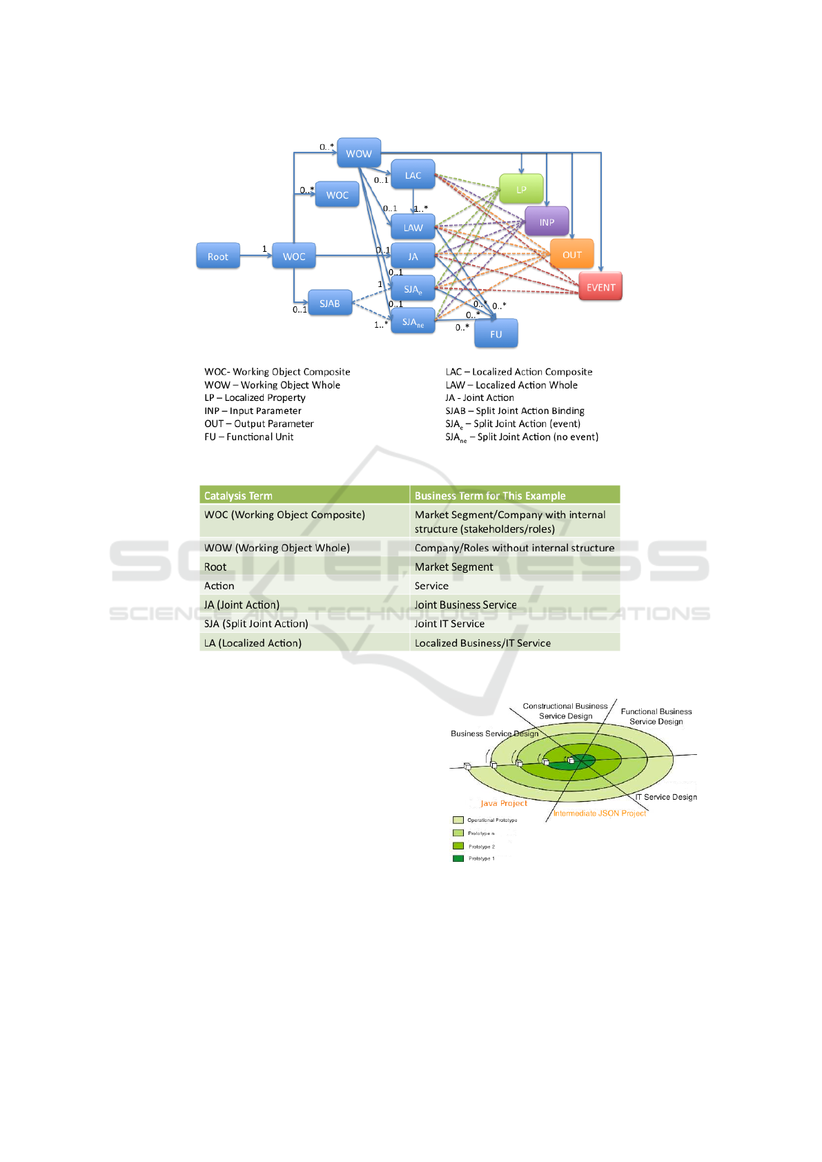
Figure 3: Meta Model.
Figure 4: Catalysis and Business Corresponding Terms.
capture the design decisions in specially formatted
matrices. In Figure 5, we show the whole process of
service design and implementation. The two orange
phases represent the service implementation part and
the black phases are service design part. As it can
be seen, after service design process, the last layer of
the IT service design can be transformed to the inter-
mediate project containing data needed by BUD tool
(Petitpierre, 2011) to generate the application. Due
to the lack of space, we will not describe the service
implementation in this paper. It is based on the BUD
tool that is based on JSON templates (JSON, 2009).
More information can be seen in (Petitpierre, 2011).
The process is shown as a spiral process (Boehm,
1986), because it combines the prototyping with the
steps of the proposed process. In this way, the de-
signer can analyse and validate how the design deci-
sions can influence the design and implementation of
Figure 5: Service Design and Service Implementation Pro-
cess.
the services.
Finally, here is the description of the model layers
and steps of the proposed design process. By conven-
tion, names from the model will be marked in italics.
From Business Services to IT Services by Capturing Design Decisions
97
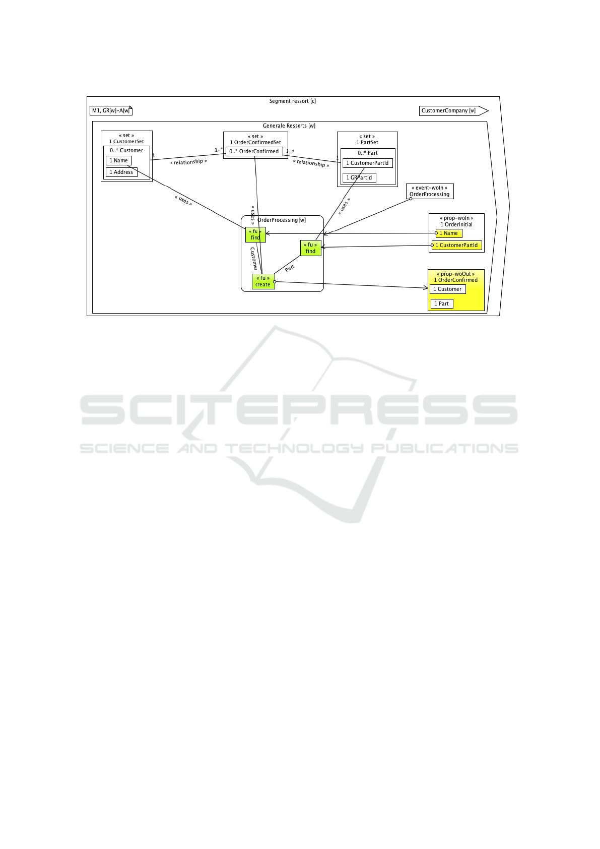
Figure 6: Business Service Design.
2.2.1 Business Service Design
In the first layer, the designer specify the business ser-
vices as in Figure 6. As it can be seen, we show a seg-
ment with company GeneralRessort and Customer-
Company. There is one main business service that is
modeled: OrderProcessing. We do not show either
the organization of the company or the sub-services
(sub-actions). Therefore, this model layer represents
the system as a whole (GeneralRessort[w]), action as
a whole (OrderProcessing[w]).
As we have mentioned in the section Modeling
Method, both the behavioural and data part of the ser-
vices are shown. The behavioural part is shown by
functional units (fu) marked in green colour. They
represent atomic operations, such as find, create, etc.
They can be parametrized by the properties related to
them (by link uses), such as CustomerSet, PartSet,
OrderConfirmedSet. Set properties represent the set
of elements of one kind, e.g. Customer. The relation
between these elements is shown by relationship. For
each property cardinality and name can be seen. De-
pending on which attribute of the Customer element
fu find is related, we can specify different operations,
such as ’find customer in the set by its name’ in Figure
6.
The inputs and outputs are marked as yellow prop-
erties. The business service order processing has
two input parameters, Name and CustomerPartId and
one output parameter, OrderConfirmed. OrderInitial
and OrderConfirmed are marked with prop-woIn and
prop-woOut. woIn and woOut mean that they come
into and go out from the system GeneralRessort from
and to outside (CustomerCompany), respectively.
Also, each service has one event (in this case
event-woIn) associated to it, showing who is initiating
the service. In this step, there are no roles, therefore
the event is shown inside the whole system General-
Ressort.
Functional units can be connected with lines that
can contain the name of the data they share, such as
Customer, meaning that fu find and create share one
data of the type Customer.
2.2.2 Joint Business Service Design
In the next model layer, the company construc-
tion is revealed and joint business services are de-
fined by providing details about the business service-
related data responsibilities within the company’s
roles. Therefore, the layer corresponds to the system
as a composite, action as a whole.
The designer defines the roles (organizational
units) in the system and distributes the service-related
data to these roles, according to their responsibilities.
This can be seen in matrices in Figure 7.
The designer defines roles: OrderEntryPerson and
ERP, marked in green in the matrices and in the next
model layer.
Then all data from the model layer in Figure 6,
shown in the rows of the matrix, are distributed to the
newly defined roles (Figure 8).
As we can see, joint business service design con-
tains defined business services without changes of the
Second International Symposium on Business Modeling and Software Design
98
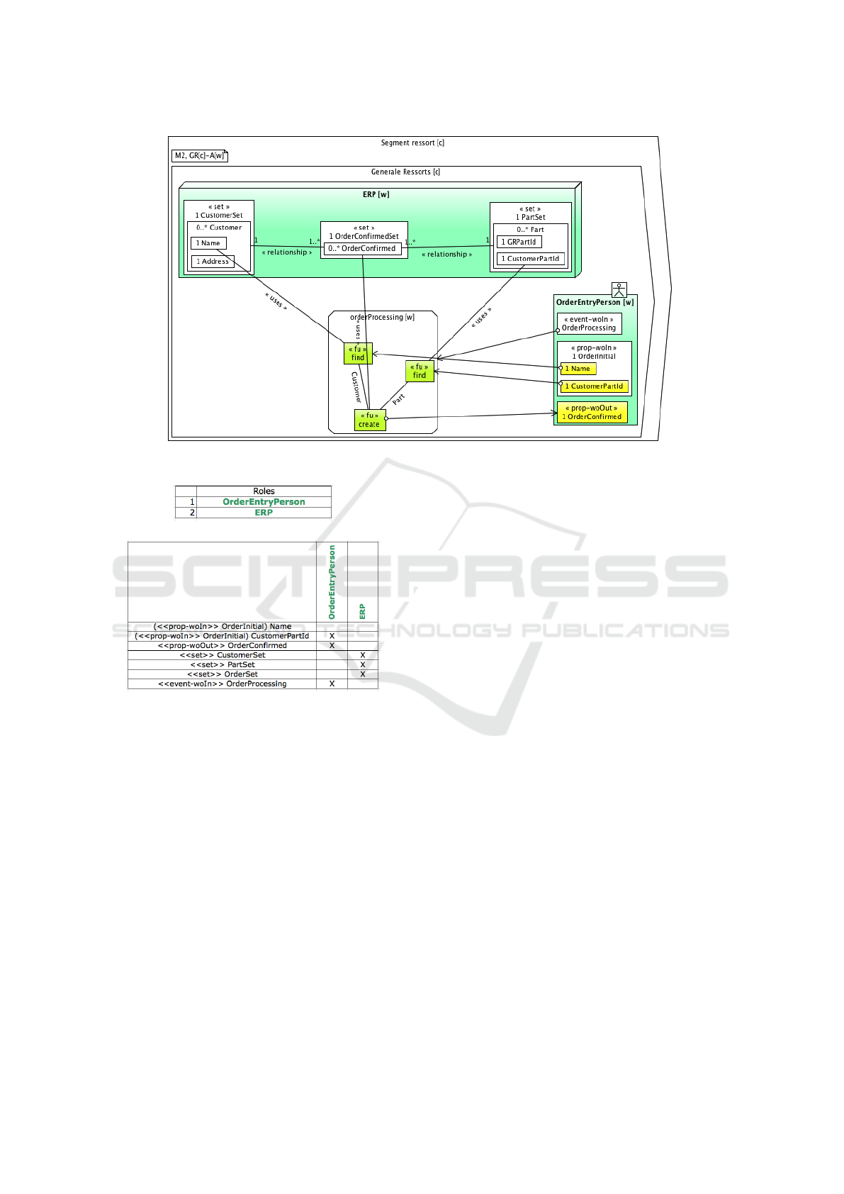
Figure 8: Joint Business Service Design.
(a) Role Definition
(b) Data Responsibility
Figure 7: Step 1 - Design Decisions from Figure 6 to Figure
8.
functional units. However, the properties related to
service, as well as the inputs and outputs are dis-
tributed to the newly defined roles. Notice that there
is still only one service defined between many roles,
it is still unknown which role is responsible for which
part of the service performance.
2.2.3 Joint IT Service Design
The next model layer defines which role performs
which part of the service. This provides insight into
the functional decomposition of the system, without
complete split of services. Therefore, this layer cor-
responds to system as a composite, action as a n-ary
relationship.
The designer defines new services of the roles and
distributes existing functional units to these service.
The designer defines two services: OrderEn-
tryPerson service and ERP service, marked in blue in
the matrices in Figure 9 and in Figure 10.
Based on the design decisions, functional units are
distributed automatically to the role’s services marked
with ’X’. Based on the arrow lines connected to the
functional units, special functional units are added to
the roles where the origin and ending of line is: en-
ter and get, respectively. enter is added when the role
initiates the fu (the line going from the role), and get
when the role obtains the result from fu (the line di-
rected to the role). This is based on the ’send-respond-
reply’ pattern described in (Beach et al., 1982). On
the lines connecting these fu, the names of the data
are written, Name, CustomerPartId, OrderConfirmed.
We show the result of added design decisions in
Figure 10. As we can see, joint IT service design con-
tains services for each role in the company, containing
some existing functional units and some newly added
ones. The properties are not changed in this step. No-
tice that there are no intermediate results in the ser-
vices, because as this is action as a n-ary relationship,
all these services represent together one service, they
are still not completely independent.
2.2.4 Localized IT Service Design
In this step, new sub-services (and implicitly their
events) are defined, and functional units are dis-
tributed to these services. Therefore, this layer rep-
resents system as a composite, action as a composite.
The designer defines new sub-services and dis-
From Business Services to IT Services by Capturing Design Decisions
99
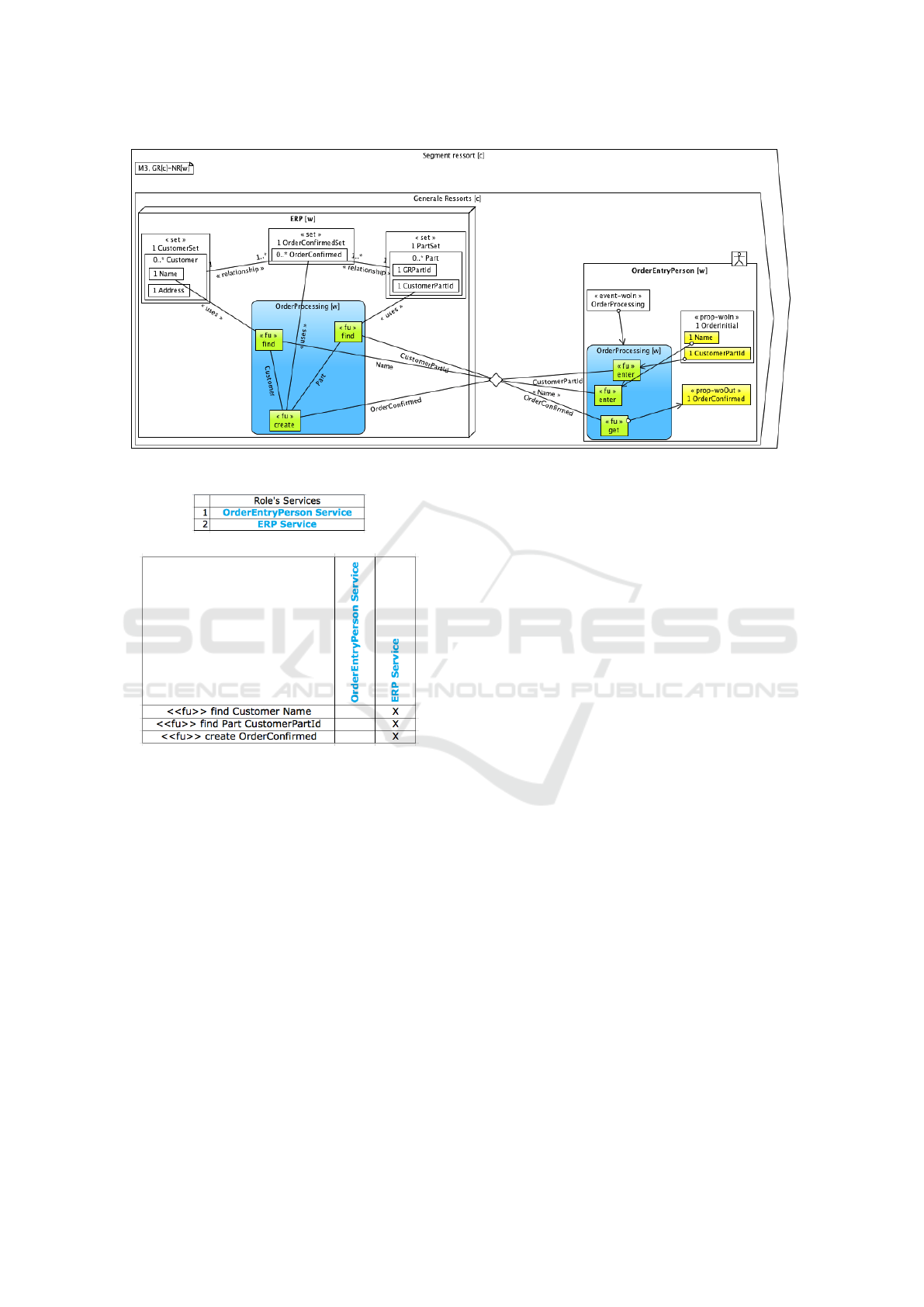
Figure 10: Joint IT Service Design.
(a) Role’s Service Definition
(b) Behaviour Responsibility
Figure 9: Step 2 - Design Decisions from Figure 8 to Figure
10.
tribute existing functional units to these services. This
is repeated for each of the roles. The events for new
sub-services are implicitly specified. Additionally,
the designer can specify that events are shared be-
tween different roles.
For example, the designer defines new sub-
services for ERP: FindCustomer, FindPart and Cre-
ateOrderConfirmed. They are marked in red in the
matrices in Figure 11 and in the resulting layer in
Figure 12. Then, the designer distributes the exist-
ing functional units of ERP to defined sub-services.
He does the similar for OrderEntryPerson, for which
he defines six sub-services. Finally, he specifies that
some events are shared, such as EnterName service of
OrderEntryPerson and FindCustomer service of ERP,
showing it is transmitted from one role to the other.
Based on the design decisions, new services are
created inside existing services containing defined
functional units as in Figure 12. In addition, some
other elements are automatically added to the model.
The lines between roles are replaced by the corre-
sponding properties in them, such as prop-woOut
Name and prop-woIn Name. Also, as we show the
sub-services, we also add the intermediate data (such
as Customer) and the corresponding fus (such as get).
These fus are also included in the distribution matri-
ces of the designer. Finally, the default IT sub-service
is added (CreateOrderProcessing), which is responsi-
ble for the basic initialization of the services in the IT
system.
All necessary data for the ERP service now ap-
pear in the ERP system, because services of all roles
are now separated and their systems contain all neces-
sary data for their services. Thus, if we would cover
completely the other roles in the model, we would be
able to see everything that is necessary for one visible
role.
This model contains IT services that are platform
independent and ready to be executed in any tar-
get language. In addition, it also contains the hu-
man services and human-human interaction, which
are very often very important to show in one consult-
ing project.
As mentioned in the service design and implemen-
tation process, by using this model layer it is possi-
ble to generate the running application for the corre-
sponding business service and its supporting IT ser-
vices as defined in this model layer.
Second International Symposium on Business Modeling and Software Design
100
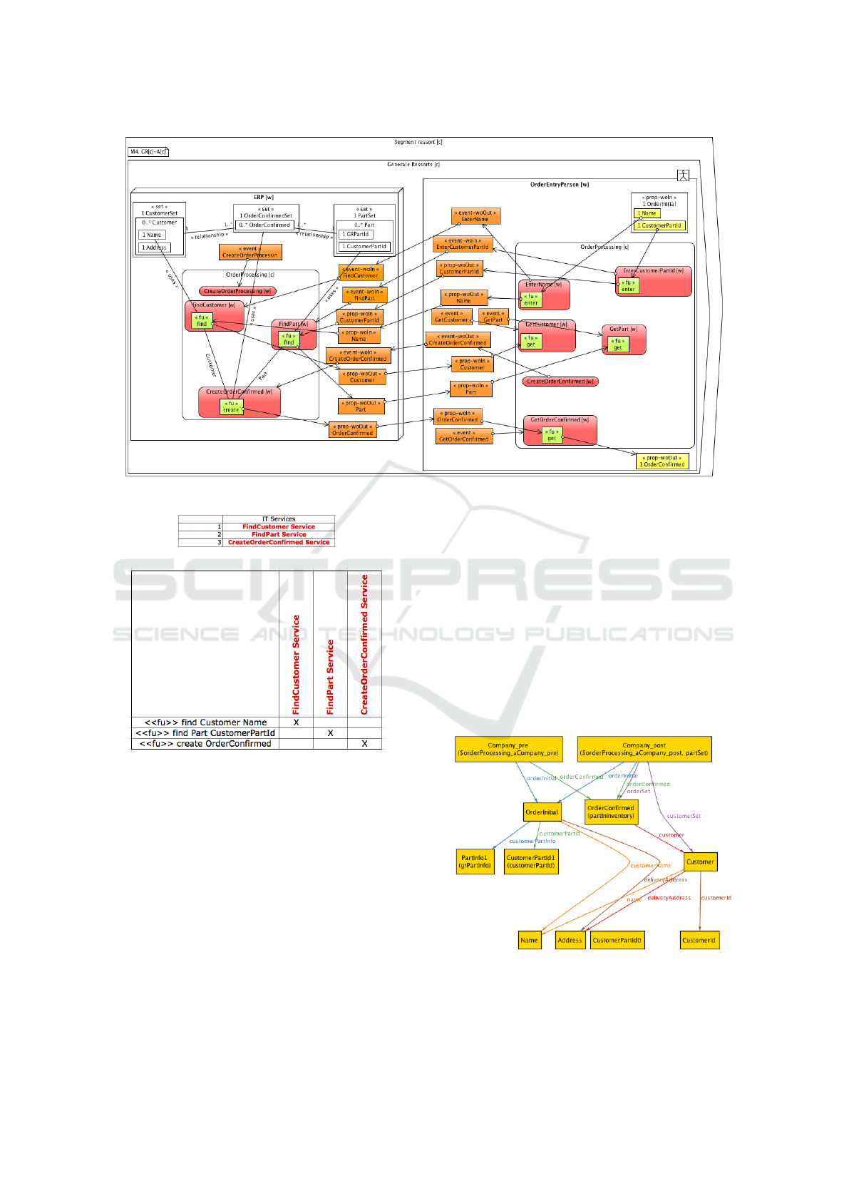
Figure 12: Localized IT Service Design.
(a) IT Service Definition
(b) Business Service Support
Figure 11: Step 3 - Design Decisions from Figure 10 to
Figure 12.
3 MODEL SIMULATION AND
PROTOTYPING
One of the main challenges in service design is ”how
to prototype services (to generate, develop, test and
evaluate ideas) throughout the design process?” (Vaa-
jakallio et al., 2009). In this section, we will briefly
explain how the prototyping is done in the proposed
approach.
In order to evaluate if the model corresponds to
the customer’s needs and requirements, this approach
enables us to prototype each of the model layers, thus
enabling the designer to simulate the behaviour of the
model layer and to find design mistakes in the early
phase. In addition, the last model can be executed
in the given target platform, which also provides one
way of validation.
In order to get the prototypes, we first formalize
the models using declarative language Alloy (Jack-
son et al., 2000), and then we run and simulate them
using the Alloy Analyzer tool (Jackson, 2011). We
use Alloy, because it can be also used to check the
refinement between different model layers, as it is ex-
plained in (Rychkova, 2008).
Figure 13: Result of Alloy model simulation.
We show in Figure 13 the result of one of the sim-
ulations of the GR case, where the customer and part
From Business Services to IT Services by Capturing Design Decisions
101

are created in case they do not exist. Company pre
and Company post are the states of the company
General Ressort, before and after the order is pro-
cessed, respectively. As we can see, they both have
the same OrderInitial that is the input to the ser-
vice and OrderCon f irmed that is output of the ser-
vice. Before the order processing, there was no cus-
tomer with the name Name given in OrderInitial, so
the new customer Customer with this name is cre-
ated in customerSet that is in Company post. And
the OrderCon f irmed contains information about that
customer and becomes member of OrderSet. We do
not provide the Alloy code here, due to the lack of
space.
So far, we have transformed manually the model
to the Alloy code, which can be run using the Alloy
Analyzer tool. The goal in the future is to automate
this simulation process. Also, the goal is to provide
simulation results in the a more business user-friendly
form.
4 RELATED WORK
We take the basic principles of our modeling tech-
nique from the Catalysis (D’Souza and Wills, 2001)
approach. Therefore, unlike some object-oriented
methods, our approach does not always begin by as-
signing responsibilities for services to specific roles.
We believe in not taking decisions all at once. We
first state what happens, then we state which role is
responsible for doing it and which one is responsible
for initiating it; and finally we state how it is done.
Another specific aspect of Catalysis overtaken in
our approach is that it places the behaviour on an
equal footing with the data. Therefore, unlike other
modeling techniques, there is only one diagram type
and each model layer contains both the objects and
actions. Also, many other approaches for business-
IT alignment of services, like (Kochler et al., 2008)
and (Buchwals et al., 2011) are process oriented,
whereas in our approach each layer contains both the
behaviour and the data.
In addition, we believe in using declarative busi-
ness process as long as possible. From our experi-
ence, very often in the projects the sequence of ser-
vices is not known. Also, in this way, the process is
more configurable, and the designer can decide in a
separate step from many possible execution paths; or
it can be concluded from the data dependency in the
model. However, in most service design approaches
(Vaajakallio et al., 2009) this is not possible.
The central aspect of our approach is the capture
of the design decisions. In this way, the designer cre-
ates the business service design and enters the design
decisions that need to be made, and the rest is done
automatically. This clearly separates the design deci-
sions of the automatic part of transformation, thus en-
abling the designers to have a multi-perspective view
of the system and to zoom in and out the models in
order to see the system with as much detail as they
need. In this way, they can quickly prototype busi-
ness requirements and evaluate several architectures.
This is something that, to the best of our knowledge,
does not exist in the other techniques.
Also, one of the challenges of the service design,
not covered very well in the techniques, is the proto-
typing of the models (Vaajakallio et al., 2009). We
also provide a simulation of the models using the Al-
loy Analyzer tool.
Besides simulations, our approach also provides
the service implementation. The whole service design
and implementation process is MDA (model driven
architecture)-based (OMG, 2001): it proposes a set
of models extending from the CIM (computation-
independent model) level, the highest level of abstrac-
tion of the MDA, to the PIM (platform-independent
model) and PSM (platform-specific model) levels.
Business service and joint business service design
correspond to the CIM level, because they represent
the context and purpose of the model without any
computational complexities. Joint IT service design
and localized IT service design correspond to PIM
level. It describes which part is done by software ap-
plication and gives its behaviour and structure regard-
less of the implementation platform. In the service
implementation part of the process, the intermediate
project containing the templates and specification ob-
jects correspond to the PSM level, because they are
strictly related to the specific application platform.
Also, in our service design and implementation cycle,
the mapping between these different levels is clearly
and systematically given.
To conclude, we provide the flexible, coherent ser-
vice design and implementation approach that follows
the standard levels of the MDA. This approach en-
ables us to clearly and systematically map between
business services and IT services, as well as to pro-
totype the different model layers and execute the IT
service layer.
5 CONCLUSIONS AND FUTURE
WORK
In this paper, we have presented a flexible, semi-
automatic, model-driven approach for aligning busi-
ness services with IT services, thus enabling the im-
Second International Symposium on Business Modeling and Software Design
102

plementation design of business services. We have
briefly presented the whole process, containing the
service design and service implementation. Then, we
have explained the service design part in more details.
We have illustrated the design process by the ex-
ample based on the consulting project conducted in
the company General Ressort based in Switzerland,
which sells parts for watches. In order to be able to
understand the example, we have explained some of
the basic characteristics of the proposed method, in-
cluding the meta-model. In the meta-model, it can
be seen that the service is characterized by: inputs,
outputs, event, functional units and properties. Inputs
and outputs are the input and output parameters of the
service, event contains information about who is ini-
tiating the service and functional units and properties
correspond to behaviour and data related to the ser-
vice.
Another important characteristic of our modeling
method is that data and behaviour are equally impor-
tant. Therefore, unlike many other modeling meth-
ods, there is only one diagram type that contains both
of them.
The proposed service design process includes four
model layers containing service design and three in-
between steps, in which the design decisions are cap-
tured. Capturing the design decisions is the central
aspect of our approach. It enables clear separation of
the decisions that need to be made by the designer and
the automatic part of transformation.
The first model layer is business service design
and the last contains IT service design, so that both the
business experts and IT experts have the perspective
of the system necessary for them. Two more layers
are added in-between, for which the user decides on
data and behaviour responsibility as two main parts of
any service design.
The layers are connected based on the design de-
cisions captured in the specially formatted matrices.
To sum up, the designer defines the business service
design, inserts necessary design decisions following
the strict rules of the proposed method. In this way,
he transforms the business service design into the IT
service design through revealing the service construc-
tion and functionality. We also provide the tool for
this transformation.
In our approach, IT service design includes human
services and human-human interactions, as from our
experience, it is very important in many consulting
projects.
Each of the model layers can be transformed to
Alloy code and simulated with the Alloy Analyzer
tool. We have also shown the example of such a sim-
ulation. In this way, it can be validated on early stage
if the models satisfy the customer needs and require-
ments and errors can be detected.
Also, the last layer has enough technical details
and can be executed on the given target platform, such
as JEE. We also provide the tool for this. However, as
it is not the main topic of this paper, we have not given
many details about it.
So far, we have tested the approach iteratively
on the laboratory examples based on the consulting
projects, specifically designed to investigate the ideas
of the proposed service design process. In the future,
we will validate the approach on real case studies,
i.e. designing in real situations (Castro et al., 2008).
Also, we will automate the transformation to Alloy
language and provide more user-friendly representa-
tions of the results of simulation.
REFERENCES
Beach, R., Beatty, J., Booth, K., Plebon, D., and Fiume,
E. (1982). The Message is the Medium: Multiprocess
Structuring of an Interactive Paint Program. Computer
Graphics Journal, 18(3).
Blecher, M. and Sholler, D. (2009). Defining Business and
SOA Services. http://www.gartner.com/id=1002314.
Boehm, B. (1986). A Spiral Model of Software Develop-
ment and Enhancement. ACM SIGSOFT Software En-
gineering Notes, 11(4).
Buchwals, S., Bauer, T., and Reichert, M. (2011). Ser-
vice Life Cycle Tools and Technologies: Methods,
Trends and Advances, chapter Bridging the Gap Be-
tween Business Process Models and Service Compo-
sition Specifications, pages 124–153. Idea Group Ref-
erence.
Castro, V., Marcos, E., and Wieringa, R. (2008). Towards
a service-oriented MDA-based approach to the align-
ment of business processes with IT systems: from the
business model to a web service composition model.
International Journal of Cooperative Information Sys-
tems, 18(2):225–260.
Chen, H. M. (2008). Towards Service Engineering: Service
Orientation and Business-IT Alignment. In Proceed-
ings of the 41st Hawaii International Conference on
System Sciences.
Crawford, C., Bate, P., Cherbakov, L., Holley, K., and Tso-
canos, C. (2005). Toward an on demand service-
oriented architecture. IBM Systems Journal, 44(1):81–
107.
Dietz, J. and Albani, A. (2005). Basic notions regarding
business processes and supporting information sys-
tems. Requirements Engineering Journal.
D’Souza, D. and Wills, A. (2001). Objects, components,
and frameworks with UML - The Catalysis approach.
Addison-Wesley, 4th edition.
Jackson, D. (2011). Alloy Analyzer tool. http://
alloy.mit.edu/alloy/.
From Business Services to IT Services by Capturing Design Decisions
103

Jackson, D., Schechter, I., and Shlyakhter, I. (2000). AL-
COA: The Alloy constraint analyzer. In Proceedings
of the 22nd International Conference on Software En-
gineering (ICSE), Limerick, Ireland.
JSON (2009). http://json-template.googlecode.com/svn/
trunk/doc/Introducing-JSON-Template.html.
Kochler, J., Hauser, R., Kuster, J., Ryndina, K.,
Vanhatalo, J., and Wahler, M. (2008). The
Role of Visual Modeling and Model Transforma-
tions in Business-driven Development. In Elec-
tronic Notes in Theoretical Computer Science, URL:
http://www.elsevier.nl/locate/entcs.
OGC (2007). ITIL v3, Glossary of Terms, Definitions and
Acronyms. http://www.itilfoundations.com.
OMG (2001). Model driven architecture. http://
www.omg.org/mda/. Document number ormsc/2001-
07-01.
Petitpierre, C. (2011). Bottom Up Creation of a DSL Using
Templates and JSON. In SPLASH’11.
Rychkova, I. (2008). Formal Semantics for Refinement Ver-
ification of Enterprise Models. PhD thesis, EPFL.
Vaajakallio, K., Mattelmaki, T., Lehtinen, V., Kantola, V.,
and Kuikkaniemi, K. (2009). Literature Review on
Service Design, extreme-design project. Technical re-
port, University of Art and Design Helsinki Helsinki
University of Technology.
Wegmann, A. (2003). On the Systemic Enterprise Architec-
ture Methodology (SEAM). In ICEIS, International
Conference on Enterprise Information Systems.
Second International Symposium on Business Modeling and Software Design
104
