
MICROWAVE WPT TECHNOLOGY DEVELOPMENTS FOR
SSPS APPLICATION
Takashi Saito , Yoshiharu Fuse, Shoichiro Mihara, Shuji Nakamura, Koichi Ijichi
Japan Space Systems(J-spacesystems) 3-5-8 Shibakoen, Minato-ku, Tokyo 105-0011 JAPAN
{Saito-Takashi, Fuse-Yoshiharu, Mihara-Shoichiro, Nakamura-Shuji, Ijichi-Koichi}@jspacesystems.or.jp
Yukihiro Homma, Takuro Sasaki
Mitsubishi Electric Corporation (MELCO) 8-1-1 Tsukaguchi-Honmachi,Amagasakicity,Hyogo,661-8661 JAPAN
Homma.Yukihiro@df.MitsubishiElectric.co.jp, Takuro.Sasaki@dn.MitsubishiElectric.co.jp
Eiichiro Fujiwara, Yuichiro Ozawa, Teruo Fujiwara
IHI Aerospace Co., Ltd. (IA) 900 Fujiki, Tomiokacity,Gunma,370-2398 JAPAN
{yuichiro-ozawa, e-fujiwara}@iac.co.jp, qfuji@js5.so-net.ne.jp
Keywords: Space solar power system (SSPS), Wireless Power Transmission(WPT), Japanese new space policy & new
space plan, Ground microwave WPT
Abstract: Japan Space Systems(J-spacesystems), formerly known as Institute for Unmanned Space Experiment Free
Flyer (USEF), has been studying Space Solar Power System as future electricity alternative energy source.
Since 2009, J-spacesystems started new research and development project of the Microwave Ground
Wireless Power Transmission under a support of Ministry of Economy, Trade and Industry. This project
includes the study for highly-efficient and thin structured phased array antenna, and the study for highly-
efficient rectenna element. Also this project plans to demonstrate ground wireless power transmission as a
previous stage to the next space proof of SSPS. In this paper, outline and progress of this project are
introduced.
1 INTRODUCTION
Japan Space Systems(J-spacesystems, formerly
USEF) has been studying Space Solar Power System
(SSPS) under a support of Ministry of Economy,
Trade and Industry(METI) and the other related
agency since 1990s. These studies were ranging
from laboratory tests to concept study of SSPS.
(Mihara et al., 2009).
In 2008, the Japanese new space policy(the Basic
Space Law) was enacted and the Basic Plan for
Space Policy was established in 2009. They have
selected "5 systems for utilization" and "4 programs
od R&D" . SSPS is one of the R&D programs. This
Plan is a five-year-program, from FY2009 to
FY2013, foreseeing the next ten years, describing
the basic policy and the measures which the
Government should take during this period.
(Strategic Headquarters for Space Policy, 2009)
In 2009, METI requested for propals for the
Microwave Power Transmission(MPT) ground
test(demonstration) according to the Basic Plan, and
the proposal of the team of J-spacesystems and
companies(Mitsubishi Electric Co. and IHI
Aerospace Co.) was adopted. (Fuse et al., 2011)
This is also a joint program between J-spacesystems
and the Japan Aerospace Exploration Agency
(JAXA). We are planning to conduct a joint MPT
ground experiment in fiscal 2014. We will
demonstrate the technologies needed to transmit a
kW class microwave precisely to the receiving site
35
Saito T., Fuse Y., Mihara S., Nakamura S., Ijichi K., Homma Y., Sasaki T., Fujiwara E., Ozawa Y. and Fujiwara T.
MICROWAVE WPT TECHNOLOGY DEVELOPMENTS FOR SSPS APPLICATION.
DOI: 10.5220/0005413600350043
In Proceedings of the First International Conference on Telecommunications and Remote Sensing (ICTRS 2012), pages 35-43
ISBN: 978-989-8565-28-0
Copyright
c
2012 by SCITEPRESS – Science and Technology Publications, Lda. All rights reserved
located 50 m from the power transmitting section. In
this joint effort, J-spacesystems is in charge of the
power transmitting section and the power receiving
section, and JAXA is in charge of the Beam Steering
Control (BSC) section. ( Miyakawa et al., 2011)
2 SSPS REFERENCE MODELS
2.1 Single-bus type Model (FY2002)
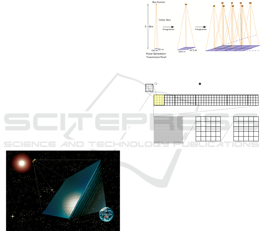
Figure 1 illustrates the concept of the tethered-SSPS
which is capable of 1.2GW power supply maximum
and 0.75GW average on the ground. It is composed
of a power generation/transmission panel of
2.0km×1.9km suspended by multi-wires(tethers)
deployed from a bus system(single) which is located
at 10 km upward. The panel consists of 400
subpanels of 100m×95m with 0.1m thickness. Each
subpanel has 9500 power generation/transmission
modules of 1m × 1m size. In each power module,
the electric power generated by the solar cells is
converted to the microwave power and no power
line interface exists between the modules. The
power module has thin film solar cells both on the
upper and lower planes. The microwave transmitting
antennas are on the lower plane. The module
contains a power processor, microwave circuits, and
their controller. Each module transmits a microwave
power of 420W maximum. (Sasaki et al., 2006)
Figure 1: Single -bus type SSPS
2.2 Multi-bus type Model (FY2006)
In 2006, the multi-bus type of SSPS was newly
proposed. Figure 2 shows the satellite structure of
the multi-bus tethered SSPS. The new SSPS system
has a multi-module structure. (see Figure 3)
In "Unit"SSPS, tethers link the bus system with the
power generation/transmission modules.
So, a "Unit" SSPS is a small "single-bus type". Each
"Unit" itself can transmit power(2.1MW) to Earth.
Several "Units" are assembled to "Unit Assemly",
and "Unit Assemly" s to "Multi-bus type"SSPS in a
similar way.
The concept of this type is, so to speak, "Start Small,
Let it Grow". (Yoshioka et al., 2011)
Figure 2: Multi-bus type SSPS
Sub-Array 4x4Antenna(0.125mx0.125m)
Module 0.5mx0.5m
Structure Unit 0.5mx5m(Minimum Structure)
Unit Assembly
(500mx475m)
SSPS System
(2500mx2375m)
Antenna for transmission Transmitting reception common antenna
Unit(100mx95m)
Figure 3: hierarchical structure of power transmitting
panels
3 MPT GROUND EXPERIMENT
MODEL
3.1 Total System
Figure 4 shows the outline of the MPT Ground
Experiment Model, and Figure 5 shows its tree
diagram. The model consists of three sections;
Power Transmitting Section
Power Receiving Section
Beam Steering Control Section (JAXA)
As for Beam Steering Control Section, Japan
Aerospace Exploration Agency (JAXA) is in charge
of the section.
First International Conference on Telecommunications and Remote Sensing
36
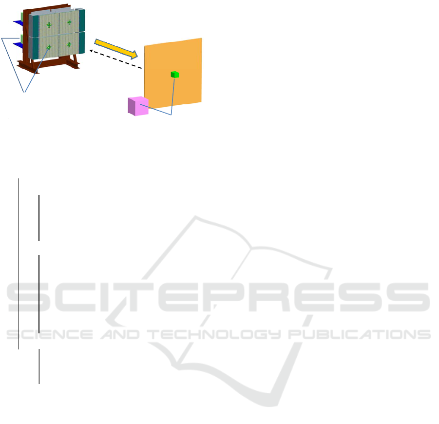
Power
Transmitting Section
Power Receiving
Section
Microwave
beam
Pilot
signal
Beam Steering Control Section
including
Pilot Signal Receiving Antenna
Beam Steering Control Section
including
Pilot Signal Transmitting Antenna
Figure 4: MPT Ground Experiment Model
MPT Ground Experiment Model
― Power Transmitting Section
―
Power Transmitting Panel
―
Reference Signal Control Master Unit
―
Power Supply
―
‥‥‥
― Power Receiving Section
―
Power Receiving Panel
―
Rectenna Control Unit
―
Battery Unit
―
―
Power Supply
―
‥‥‥
― Beam Steering Control Section (JAXA)
―
Pilot Signal Transmitting Antenna
―
Pilot Signal Receiving Antennas
―
‥‥‥
Power Receiving Section
Monitor & Control Unit
Figure 5: Tree Diagram of Ground Experiment Model
To realize SSPS, each section needs to have
following features;
for Power Transmitting Section,
light weight and thin power
transmitting modules (transportation
and construction cost)
high efficiency (heat discharge and
power generation cost)
for Power Receiving Section,
electrical robustness (stable operation
and maintenance cost)
high efficiency (power generation cost)
for Beam Steering Control Section
beam steering control accuracy (safety)
To solve these problems, our solutions are;
for Power Transmitting Section,
to develop a thin sub-array
to apply highly efficient HPA to GaN
HEMT, F-class amplifier
for Power Receiving Section,
to find out the cause of rectenna damage
to develop a highly efficient diode
for Beam Steering Control Section
retro directive method (using pilot
signal)
rotating electromagnetic vector method
(REV method)
Beam Steering Control Section has;
Pilot Signal Transmitting Antenna
(Power Receiving Section)
Pilot Signal Receiving Antenna
(Power Transmitting Section)
The microwave beam frequency is 5.8GHz, and the
pilot signal frequency is 2.4GHz band. (Miyakawa
et al., 2010)
3.2 Power Transmitting Section
3.2.1 Basic Design
The basic design concept of the power transmitting
section is as follows;
High power (kW-class)
High efficiency of DC-RF conversion
Thin phased array (Sub-array)
Principled reference signal control
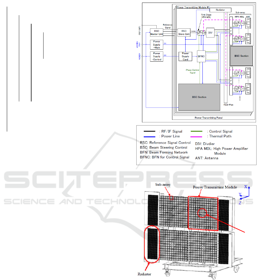
Tree diagram of Power Transmitting Section is
shown in Figure 6. And the system block diagram of
the power transmitting section is shown in Figure 7.
Microwave WPT Technology Developments for SSPS Application
37
Power Transmitting Section
―
Power Transmitting Panel
―
Power Transmitting Module (x4)
―
Sub-array (x76)
―
Antenna (x4)
―
HPA Module
―
Beam Forming Network (BFN)
―
Divider
―
First Stage HPA Module
―
BFN for Control Signal (BFNC)
―
Power Supply Card
―
Reference Signal Control Slave Unit
―
Reference Signal Control Master Unit
―
Power Supply
Figure 6: Tree Diagram of Power Transmitting Section
Four power transmitting modules, which are phased
array antennas, constitute of the power transmitting
section.
A sub-array is the minimum unit. It consists of a
BFN, an HPA module(MDL) and four sub-array
antennas. A BFN receives microwave, DC power
and control signal, and feeds them to the HPA MDL.
Each HPA MDL has a phase-shifter, a driver
amplifier, a high power amplifier and so on. Then, it
provides microwave to four sub-array antennas.
A power transmitting module has 76 Sub-arrays.
The module size is 60cm square. One module can
output more than 400W. So the power transmitting
panel(4 modules) size is about 1.2m square and the
output power is about 1.6kW.
Figure 8 shows the outline view of Power
Transmitting Section. Pilot Signal receiving antenna
is set in the center of each power transmitting
module (PT module). It is used for beam steering
control.
Each PT module transmits microwave beam to the
right direction according to the phase control signal
from the beam steering control section. A PT
module generates microwave in accordance with the
reference signal from RSC master unit. This
microwave is amplified by HPA modules (first stage
and sub-array) using DC power from the main
power supply, and divided by the divider, distributed
to the sub-array antennas, and then transmitted.
Figure 7: Block diagram of the power transmitting section
PilotSignal
Receiving
Antenna
Figure 8: Outline view of power transmitting section.
As for SSPS, relative positions among the power
transmitting modules may change. Power
Transmitting Section has a function to simulate this
situation by moving PT modules manually, for the
purpose of verifying the effectiveness of the beam
control method under that condition .
First International Conference on Telecommunications and Remote Sensing
38
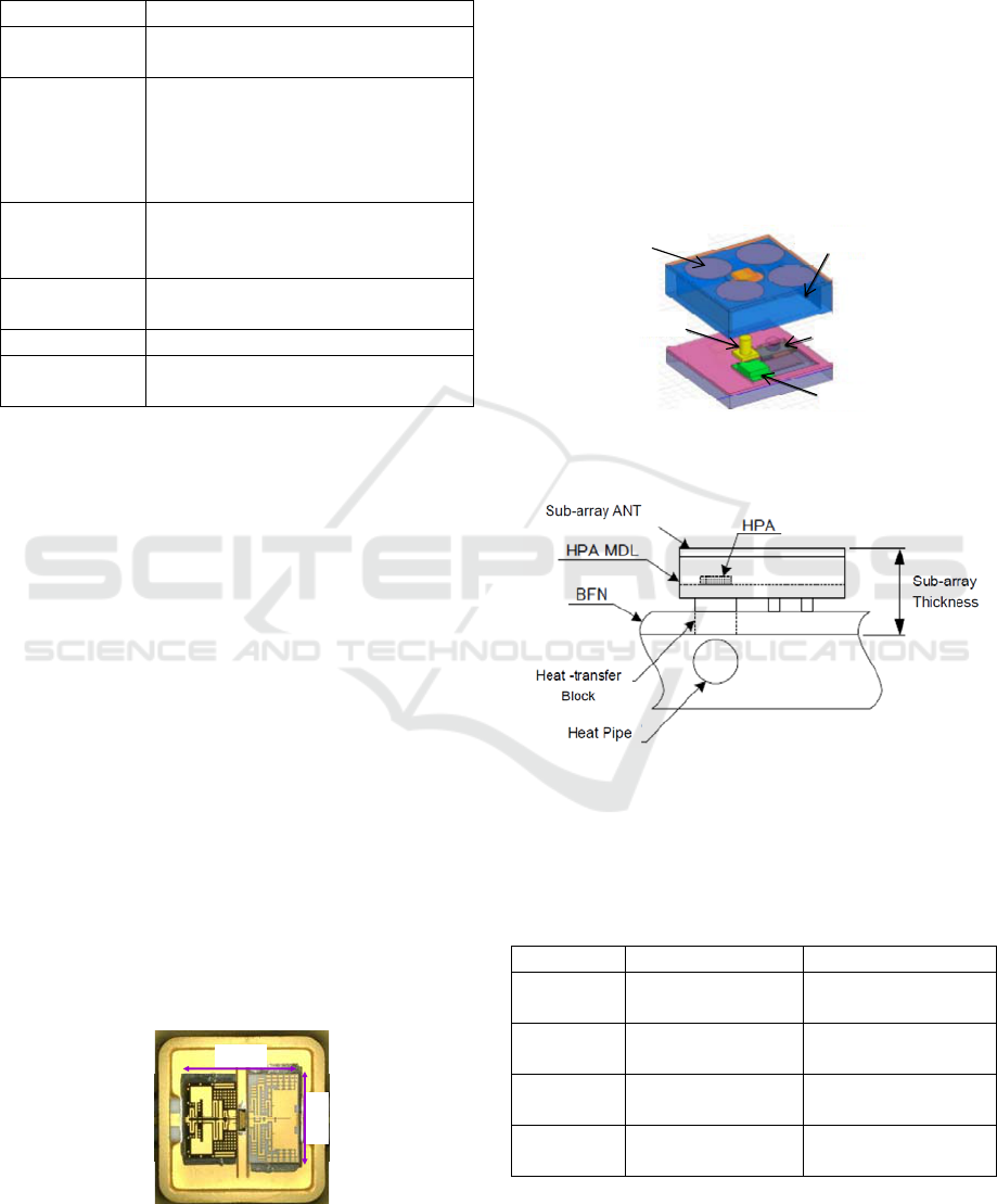
Table 1 shows the specifications of power
transmitting section.
Table 1: Specifications of Power Transmitting Section
Item Specification
Microwave
Frequency
5.8GHz±75MHz
Power
Transmitting
Modules
Number: 4
Size: ≈0.6m x 0.6m
Thickness: ≤40mm (Sub-array)
Efficiency: ≥30% (PT module)
Mass: ≤19kg (Sub-arrays)
High Power
Amplifier
(HPA)
GaN HEMT with F-class
76 HPAs (per PT module)
Efficiency (PAE): ≥60% Ave.
Antenna
Spacing
0.65λ (33.6±1 mm)
Phase Shifter 5 bit (MMIC)
Transmitting
Power
≥400W (per PT module)
≥1600W (total)
As for the following items, our policy is;
to get low loss Sub-array antenna for
high efficiency, rather than for thickness.
to get thin, light Sub-array structure
to make a good balance between high
efficiency and thickness of HPA
module
GaN HEMT with F-class power amplifier is applied
to the power transmission section. GaN HEMT has
attracted much attention as the state-of-the-art
microwave power transistor due to its high voltage
and high power density capability. F-class operation
was applied for high efficient power amplifier
operation. In this work, an internally matched GaN
HEMT high efficient amplifier is developed, in
which 2nd harmonic at input side and 2nd and 3rd
harmonic at outside are tuned with internal matching
circuit. Very high Power Added Efficiency(PAE)
70%, with 7W output power was successfully
obtained. Figure 9 is the photograph of hermetic
sealed metal packaged GaN HEMT high efficienct
amplifier. (Yamanaka et al., 2010)
8.0mm
6.4mm
Figure 9: Metal packaged GaN HEMT amplifier
For space application, antenna thickness is very
important parameter. Because the huge sized SSPS
requires light weight for lower cost transportation
and also requires the expansion structure in space.
Figure 10 is the ideal image of thin sub-array
structure. Vertical circuit for the connection of the
micro wave circuit board to the antenna array
substrate was applied for the thickness reduction.
The achievement of the thickness was 44.4mm in
our early design. We are trying to reduce the
thickness with keeping low loss performance.
(Namura et al., 2010)
High Power Amp
connector
sealed cover
isolator etc.
antenna elements
Figure 10: Sub-array radiation part structure image
Figure 11: Sub-array thickness
According to above studies, a new design target is
set as Table 2.
Table 2: Design Target (typical)
Item Specification Target
Output
Power
≥400W
per PT module
411W
per PT module
Efficiency ≥30%
as PT Section
35%
as PT Section
Sub-array
Thickness
≤40mm 34mm
Sub-array
Mass
≤19kg 19kg
Microwave WPT Technology Developments for SSPS Application
39
3.2.2 Element Test
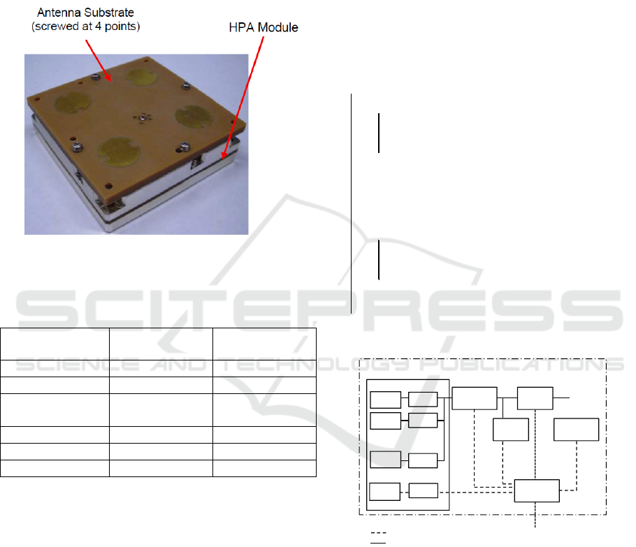
In FY2011, a performance verification test of the
HPA module(trial product, see Figure 12) was done.
It consists of HPA module, Sub-array ANT, BFN etc.
It became certain that all test results meet the design
target (see Table 3).
Figure 12: HPA module(trial product)
Table 3: HPA module(trial product) Test Result
Item Design
(average)
Test
(average)
Output Power ≥6.1W 6.17W
Efficiency(PAE) ≥40.2% 41.50%
Accuracy of
Phase-Shift
≤3deg
rms
2.1deg
rms
Spurious ≤ - 60dBc - 65.7dBc
Size 62x62x14.6mm 62x62x14.6mm
Mass 92g 91.3g
We are going to examine the ongoing design of PT
module(e.g., performance, size, mass, heat radiation)
and make a prototype of sub-array.
3.3 Power Receiving Section
3.3.1 Basic Design
A tree diagram of Power Receiving Section is shown
in Figure 13. And the system block diagram of the
power receiving section is shown in Figure 14.
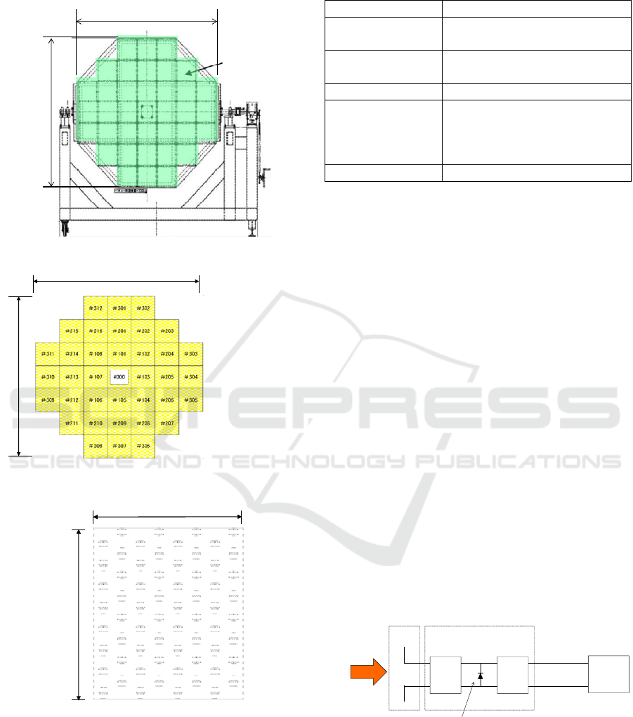
Power receiving panel consists of 37 power
receiving modules. The pilot signal transmitting
antenna is set in the center module. (see Figure 15
and Figure 16)
Power Receiving Section
―
Power Receiving Panel
―
Power Receiving Module (x37)
―
Panel Structure
―
Rectenna Control Unit
―
Battery Unit
―
Power Receiving Section Monitor & Control Unit
―
Ground Test Equipment
―
Remote Control Unit
―
Power Distribution Unit
―
Power Supply
Figure 13: Tree Diagram of Power Receiving Section
受電モジュール
受電部
受電
アンテナ
レクテナ
制御ユニット
受電部制御
監視ユニット
電力分配
ユニット
DC出力
電力モニタ
アンテナ
モニタ回路
受電
アンテナ
整流回路
整流回路
整流回路
・
・
・
受電
アンテナ
蓄電池
ユニット
受電部遠隔
操作ユニット
ビーム方向制御部へ
信号
電力
Power Receiving Section
Antenna
Antenna
Antenna
Power Receiving Section
Rectifying
Circuit
Rectifying
Circuit
Rectifying
Circuit
Monitor
Antenna
Monitor
Circuit
Rectenna
Control
Unit
Power
Distribution
Unit
DC output
Battery
Unit
Remote
Control
Unit
PR Section
Monitor & Control
Unit
to Beam Steering Control section
Signal
Power
Figure 14: Block diagram of the Power Receiving Section
Table 4 shows the specifications of power receiving
section. The diodes used in the power receiving
module are "regular type"(commercialized product) .
The RF-DC efficiency(antenna to rectenna control
unit) is estimated by efficiencies of :
antenna polarization
rectifying circuit
rectenna control unit.
First International Conference on Telecommunications and Remote Sensing
40
As a result, the RF-DC efficiency is estimated to be
56.8%.
2.5m
2.2m
2.6m
Power
Receiving
Module
Figure 15: Power Receiving Section
2.6m
2.2m
Figure 16: Power Receiving Panel (Rectenna Array)
0.32m
0.37m
Figure 17: Power Receiving Module
Table 4: Specifications of Power Receiving Section
Item Specification
Power Receiving
Panel
Size : 2.6m × 2.2m
Power Receiving
Module
Number: 37
Size: 0.37m x 0.32m
Diode type Schottky barrier diode
RF-DC
Efficiency
≥ 50% (Regular type, Power
Receiving Panel)
≥ 80% (Advanced type,
Rectenna Element)
Receiving Power ≥300W (estimated)
3.3.2 Element Test
Figure 18 is the typical block diagram of a rectenna.
Self-bias rectifying circuit is used in a rectenna.
This circuit has input filter, rectifying diode and
output filter. Most of the power loss will be caused
by the loss in rectifying diode. There have been
several reports on the causes of the loss in diode.
(McSpadden et al., 1998)
In parallel to designing power receiving module, we
are trying to develop a high efficient Schottky
barrier diode for rectifier using GaN material
(Advansed type). In this development, an
experimental evaluation of the manufacturing
process and the manufacturing condition have been
done. (Ozawa et al., 2010)
We are considering improvement of efficiency with
studying parameters as follows:
Cj
0
: junction capacitance(zero bias)
Rs: series resistance
Vbi: built-in voltage
Vbr: breakdown voltage
Antenna
Rectifying Diode
Rectifying Circuit
Input
Filter
Output
Filter
Resistive
Load
DC PWR
Microwave
5.8GHz
Patch
Antenna
Shottoky
barrier diode
Self-biased
Rectifying Circuit
Figure 18: block diagram of a rectenna
A trial modelshows more efficiency than that of
existing "Regular type". We continue making an
effort to improve "Advansed type" diode.
Microwave WPT Technology Developments for SSPS Application
41
4 MPT GROUND TESTS
We are planning the indoor and outdoor MPT tests.
They wil be completed by fiscal 2014.
4.1 Indoor Test
Outline of the indoor(laboratory) test is shown in
Table 5.
Table 5: Outline of the indoor test
Facility anechoic chamber
Test Equipment Power Transmitting
Module × 4
Power Transmitting
Distance
≥10 meters
Beam Pointing
Accuracy
≤0.5 degrees (rms)
Microwave Frequency 5.8GHz±75MHz
Pilot Signal Frequency 2.4GHz band
(Miyakawa et al.,2011)
4.2 Outdoor Test
Outline of the outdoor(field) test is shown in Table 6.
Table 6: Outline of the outdoor test
Facility outdoor field
Test Equipment MPT Ground
Experiment Model
(Power Transmitting
Module × 4)
Power Transmitting
Distance
≈ 50 meters
Transmitting Power ≈ 1.6kW (411W×4)
Power Flux Density
@center, 50m
315W/m2±20%
(estimated)
Output Power ≈ 0.3kW (estimated)
The objectives of the field test, or the demonstration,
are;
to transmit kW-class power
to prove precise beam pointing
accuracy(retro-directive, REV method)
to demonstrate WPT (e.g., to feed
electricity from rectenna to home
electrical appliances
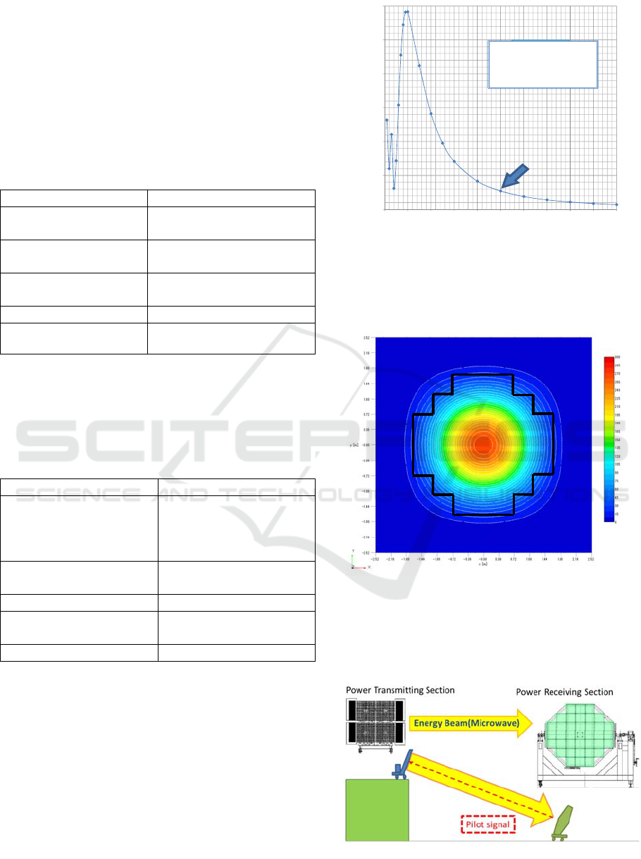
The energy electricity flux density at the receiving
position center is calculated in Figure 19.
0
500
1000
1500
2000
2500
3000
0 102030405060708090100
P(W/m2)
送電距離 Z(m)
nfcu
5.8[GHz]
パネル 1.2x1.2[m]
送電電力 1.3[kW]
nfcu
5.8GHz
antenna1.2x1.2[m]
power1.3 [kw]
P(w/m2)
Z(m)
Figure 19: Electricity flux density
An energy distribution at 50m point is analyzed as
shown in Figure 20. The black flame in the figure is
shape of the receiving panel.
Figure 20: Energy distribution at 50m point
Figure 21 shows a WPT demonstration image.
Layout of power transmitting/receiving sections is
to be determined, avoiding any radio wave
interference.
Figure 21: WPT Demonstration Image
First International Conference on Telecommunications and Remote Sensing
42

CONCLUSION
Microwave Ground WPT project is currently going
on. Basic design and element tests are in progress.
We are planning to conduct the MPT ground
experiment in FY 2014 in collaboration with JAXA.
We have started to develop a concrete plan for the
demonstration. And we should always be conscious
that this ground demonstration is a preliminary step
toward the next step of demonstration in space.
ACKNOWLEDGMENTS
The chairman of Microwave Power Wireless Power
Transmission Technology Committee is Prof. Naoki
Shinohara, Kyoto University. This committee
consists of 12 members. Research and development
related to the beam steering control section is shared
with Japan Aerospace Exploration Agency, JAXA.
J-spacesystems is working with Mitsubishi Electric
Corporation, MELCO at Power Transmitting section,
and with IHI Aerospace Co., Ltd., IA, at Power
Receiving section. This project is supported by the
Ministry of Economy, Trade and Industry, METI.
REFERENCES
Fuse, Y., Mihara, S., Saito, T., Ijichi K., Namura, K.,
Homma, Y., Sasaki, T., Ozawa, Y., Fujiwara, E.,
Fujiwara, T., 2011. Microwave Energy Transmission
Program for SSPS, CHGBDJK.2 URSI GAS2011, Aug.
2011
McSpadden, Lu Fan, J., Kai Chang, K., 1998. Design
and Experimental of a High-Conversion-Efficiency 5.8-
GHz Rectenna, IEEE Trans. MTT, Vol.46, No.12,
1998, pp2053-2060
Mihara, S., Saito, T., Kobayashi, Y., Kanai, H., 2007.
Activities for the Realization of Space Solar Power
Syatem at USEF, S1-I-1408 URSI ISRSSP2007, Sep.
2007
Miyakawa, T., Sasaki, S., Yajima, M., Maki, K., Mihara,
S., Fuse, Y., Saito, T., Ijichi, K., Homma, Y., Sasaki,
T., Ozawa, Y., Fujiwara, E., Fujiwara, T., 2011.
Development Status of Microwave Power Transmission
Demonstration on Ground for Space Solar Power
Systems, IAC-11-C3.2.2, 62nd International
Astronautical Congress, Oct. 2011
Namura, K., Honma, Y., Sasaki, T., Samejima, F.,
Ishikawa, T., Fuse, Y., Saito, T., Mihara, S., 2010.
Studies on Transmission Subsystem for Ground WPT
Experiment System, 1S12 54th Space Science
technology symposium, 2010
Ozawa, Y., Fujiwara, E., Fujiwara, T., 2010. Study on
technical demonstration model of microwave receiving
System, 1S14 54th Space Science Technology
Symposium, 2010
Sasaki, S., Tanaka, K., Higuchi, K., Okuizumi, N.,
Kawasaki, S., Shinohara, N., Senda, K., Ishimura, K.,
2006. A New Consept of solar power satellite:
Tethered-SPS, Acta Astronica 60, 2006, p153-165
Strategic Headquarters for Space Policy, 2009. Basic Plan
for Space Policy, June 2009
Yamanaka, K., Tsuyama, Y., Ohtsuka, H. Chaki, S.,
Nakayama, M., Hirano, Y., 2010. Internally-Matched
GaN HEMT High Efficiency Power Amplifier for
Space Solar Power Stations, WE3A-1, APMC2010
Yoshioka, K., Matsuoka, H., Hayami, H., Collins, P.,
Sasaki, S., Takano, T., Asakura, K., Nakano, S., 2009.
Essays on the Solar Power Satellite, Keio University
Press, 2009
Microwave WPT Technology Developments for SSPS Application
43
