EVALUATION OF ESD EFFECTS ON SOLAR ARRAY
in Different Space Missions
Omid Shekoofa, Maryam Baghban Kondori
Space Research Institute (SRI) of Iranian Space Agency (ISA), 14
th
St. Sa’adat Abad, Tehran, Iran
omid.shekoofa@sri.ac.ir, m.baghban@sri.ac.ir
Keywords: Electrostatic Discharge, Solar Array, Electrical Power Subsystem.
Abstract: This paper studies the electrostatic discharge effects on solar arrays in different orbits. This paper starts with
a statistical overview of solar array failures and their relations with ESD events. Then the space
environmental conditions and their impacts on ESD occurrence are discussed for the most commonly used
orbits for satellite missions. Spacecraft charging phenomena and different modes of charging are studied
further in the paper. Finally the effects of ESD events on the elements and subassemblies of solar arrays are
investigated.
Increase in energy demand in new high power
telecommunication and observation satellites leads
to need for higher power generation by their
electrical power subsystems (EPS), which requires
larger area of solar arrays (SA). Larger SA provide
more power, and deliver it to the loads through
higher voltage buses, which made them more
susceptible to Electrostatic Discharge (ESD).
At the same time increase in power consumption
may require a higher level of current drawn from a
typical primary regulated bus, that in turn augments
the risk of ESD event on SA cables and the whole
harness subsystem of the satellite. Therefore more
knowledge about ESD and its impacts on the EPS,
especially on SA design and operation, is an
essential requirement in designing high power
satellites.
Immunity against ESD is an essential requirement in
subsystem level for designing the EPS of a satellite.
Among all the EPS elements and parts, SAs are the
most susceptible one to ESD effects. ESD events
can take palce on SA and most of its subassemblies
like solar cells, coverglasses, metallic frames, cables
and connectors, in different conditions which are
exist in various space missions.
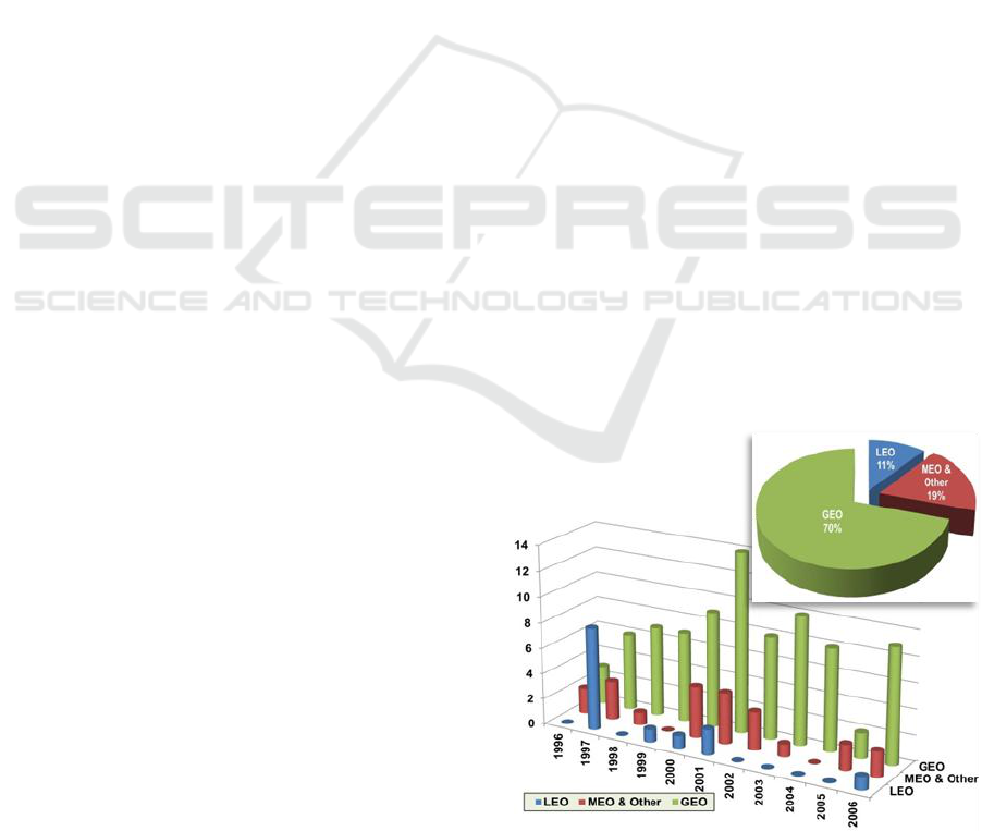
During ten years of space missions (1996-2006),
more than 47% of the numbers of insurance claims
for the satellite failures were because of the EPS
faults and anomalies. Almost the half of the costs of
these failures are related to SA anomalies, and more
than 90% of the array anomalies are due to the
failures in their elements and subassemblies
operation. The majority of these in-orbit failures and
anomalies are originated from ESD events on SA.
The bar-chart in figure 1 shows the number of SA
anomalies in different orbits during 1996-2006 and
the pic-chart at top right side of figure 1, displays the
percentages of these anomalies (Rodiek, 2008).
Figure 1. The numbers of solar array anomalies in
different orbits during 1996-2006 (bar-chart), and the
percentages of these anomalies (pic-chart at top right)
94
Shekoofa O. and Kondori M.
EVALUATION OF ESD EFFECTS ON SOLAR ARRAYin Different Space Missions.
DOI: 10.5220/0005414500940098
In Proceedings of the First International Conference on Telecommunications and Remote Sensing (ICTRS 2012), pages 94-98
ISBN: 978-989-8565-28-0
Copyright
c
2012 by SCITEPRESS – Science and Technology Publications, Lda. All rights reserved
In order to avoid such dominant risk in SA
operation, it is required to consider the ESD
phenomenon, the enviromental conditions for ESD
occurrence and its causes in designing SA. It is also
needed to apply adequate ESD control and
mitigation techniques in the EPS manufacturing and
assembly process.
The main reasons for ESD occurance on SA is the
accumulation of electrical charges on the SA
surface. Whenever charge buildup takes place, there
will be the risk for ESD event. The existent space
environment which surrounds the whole satellite,
generates the required conditions for causing the
ESD events. Satellites in different orbits encounter
different environmental conditions like plasma and
Sub-storms. Therefore they experience different
levels of internal and external charging which might
lead to different levels of risks for ESD occurrence.
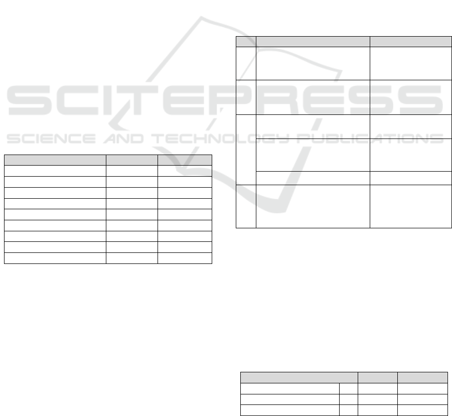
In table 1, three different levels are defined for
the possibility of spacecraft (SC) charging in
different orbits (Mazur, 2003). These levels are in
compliance with the illustrated information in figure
1. Table 1 also shows different possibilities for
charging on SC surface and internal parts which will
be discussed in continue of this paper.
Table 1: Spacecraft charging levels in different orbits
Orbit
Surface
Internal
LEO, Inclination <60
Low
Low
LEO, Inclination >60
Medium
Low
PLEO
High
Medium
MEO
High
High
GPS
High
High
GTO
High
High
GEO
High
High
HEO
High
High
Interplanetary
Low
Low
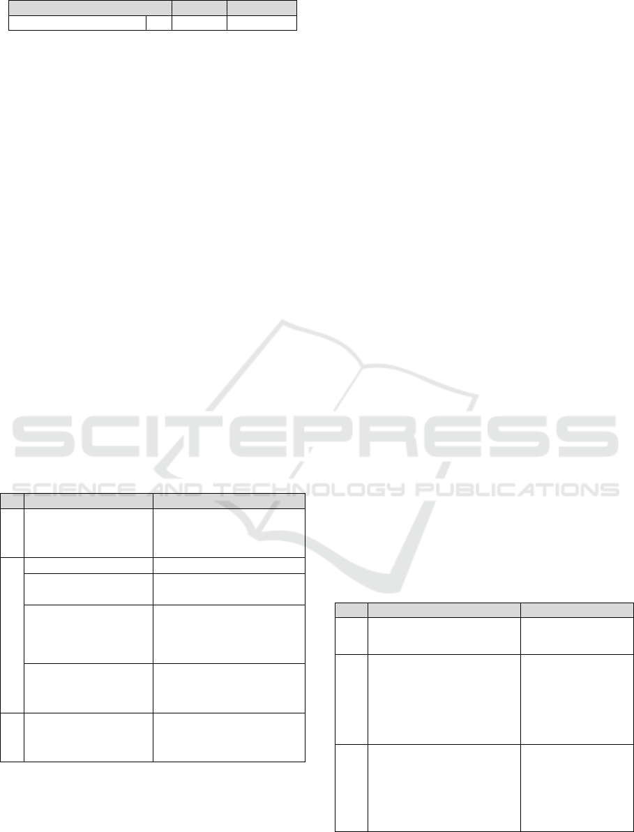
According the information of table 1 and
regarding the importance of GEO and LEO orbits
for satellite missions, the environmental conditions
in these orbits are considered in more detail in
sections 3.1 to 3.3, and summarized in table 3 (ISO
11221:2011).
3.1 GEO Conditions
GEO is characterized by the presence of electrons
with energies (E
e
) greater than 1keV. In GEO orbit
two different conditions may be considered:
Quiet condition: refers to a condition where in
the absence of solar sub-storms the current of
the incident electrons (J
e
) is less than the
photoelectron current (J
ph
)
Stormy conditions: where J
e
is higher than J
ph
3.2 LEO Conditions
LEO is characterized by the presence of low energy
but dense ionospheric plasma. For an object in this
condition, current from electrons of energies 0.1 to
0.2 eV dominates over any other current source to
spacecraft.
3.3 Polar LEO Conditions
Polar LEO (PLEO) is characterized by auroral
electrons, with energies greater than 1keV, which
coexist with the low energy ionospheric plasma.
Table 2: The specifications of different orbits’ conditions
Conditions
Specifications
GEO
Quiet
High energy electrons
(No magneto-spheric
substorms)
E
e
> 1keV
J
e
< J
ph
=10µA.m
-2
GEO
Stormy
High energy electrons +
Emitted secondary electrons
(Magneto-spheric substorms)
E
e
> 1keV
J
e
> J
ph
LEO
Low energy but dense
plasma,
Particles density
10
8
to 10
12
m
-3
Attracted ions to the
negatively charged SC body
J
e
is generated by
electrons with E
e
0.1 to 0.2 eV
SA bus voltage level
V
SA-BUS
>100 V
PLEO
Auroral electrons + Low
energy ionospheric plasma
LEO-like dense plasma+
GEO-like high energy plasma
E
e
>1keV
J
e
= 1mA.m
-2
> J
ph
Since the actual space environments are not known
precisely, it is common to use a simulated
environment for numerical simulations and
calculations purposes instead. For example, NASA
recommended “worst case” charging environment is
presented in table 3. Sensitivity studies have shown
that the actual condition for SC charging is much
less severe than these conditions (Katz, I., and
others, 2000).
Table 3: NASA Simulated Environment Parameters
Parameter
Value
Dimension
Electron number density
n
e
1.12×10
6
m
-3
Electron temperature
T
e
12
keV
Ion number density
n
i
2.36×10
5
m
-3
Evaluation of ESD Effect on Solar Arrays and Methods of Control and Mitigation
95
Parameter
Value
Dimension
Ion temperature
T
i
29.5
keV
The essential reason for ESD occurrence is the SC
charging. In different missions with various orbit
parameters, different charging conditions may exist.
For example, a typical ESD event can occur under
the following conditions (NASA Report, 2007):
Vacuum pressure <10
-5
torr, and either
Dielectric surface voltage is greater than 500V
The electric field between a dielectric surface
and a conductor is greater than 10
5
volts/cm.
Each of these two electrical characteristics can
be generated by a certain environmental condition.
This is why the probability of ESD occurrence
directly depends on the space condition in the
studied orbit. For instance the electrical
characteristics, such as electrostatic potentials (V
ES
)
of the various parts of the SC, in a GEO satellite can
be totally different than the similar parameters for a
LEO satellite due to the different charging levels.
Some of these differences are presented in Table 4.
Table 4: Charged parts and the relevant electrical effects
in different orbits
Charged Parts
Electrical Effects
GEO
SC body (between
adjacent surfaces)
V
ES
= V
SC
several hundred
to several thousand volts
(particularly during sunlit)
LEO
SC body
Charging rate −5 V/s.
Coverglass and
underlying cell
V
ES
several hundred volts
dv/dt 3 V/s
The front surface of the
SA faces the Sun
J
e
(consisted of charges
which are constantly bled
off via photoemission from
cell coverglasses)
Gaps between the solar
cells, (shaded by the
edges of the solar cells)
Negatively charged
PLEO
SC body
V
SC
< V
SA-BUS
According to table 1 there are two types of charging
for spacecrafts: surface charging and internal
charging. Surface charging consists in the charging
on visible and touchable areas of the external part of
the satellite. Internal charging is resulted from the
penetration of energetic electrons into the satellite
enclosures (like Ebox) and deposit charge very close
a victim site. Since ESD on SA mainly occurs
because of surface charging, this type of charging
will be more discussed.
5.1 Surface Charging
Surface charging may cause ESDs and arcing on
solar arrays and their power cables. It is generally
caused by electrons of 5-50 keV in GEO, 2-20 keV
in PEO, or high voltage arrays in LEO (Cho, M,
2007). Table 5 provides more information on the
causes and effects of charging in different orbits
(Ley, W., and others, 2009) (Leung, P, 2010). It
should be mentioned that there are two types of
potential gradients noted in table 4 as follow:
Normal Potential Gradient (NPG) which is
resulted of differential charging where the
insulating surface or dielectric reaches a
negative potential with respect to the
neighboring conducting surface or metal. It is
sometimes referred as Negative Dielectric
Positive Metal (NDPM) condition.
Inverted Potential Gradient (IPG), which is
also called Positive Dielectric Negative Metal
(PDNM) mode, is the result of differential
charging where the insulating surface or
dielectric reaches a positive potential with
respect to the neighboring conducting surface
or metal.
Table 5: Charging causes and issues in different orbits
Charging Causes
Charging Issues
GEO
Quiet
E
e
5-50 keV
No serious surface
charging issue
GEO Stormy
SC potential:
Dielectric charged: +
In sunlit: 10
2
to 10
3
orders
of Volts between adjacent
surfaces
IPG
LEO
High voltage arrays
V
SC
floats with respect to
the ionospheric plasma
potential, within V
SA-BUS
range
IPG
Min (V
SC
)= V
SA-BUS
V
Discharge
−200 V
First International Conference on Telecommunications and Remote Sensing
96
Charging Causes
Charging Issues
PLEO
E
e
2-20 keV
Driving V
SC
to a potential
more negative than V
SA-BUS
Min (V
SC
)= V
SA-BUS
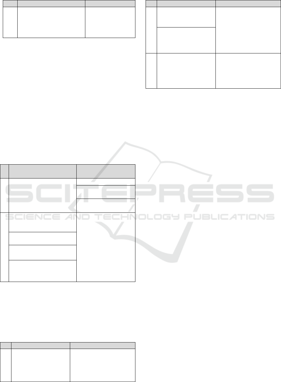
5.2 Charging Status during In-orbit
Operation
When the satellite continuously passes through
cyclic sunlit and eclipse phases, the environmental
conditions of the satellite change in the same cyclic
manner. In table 6 typical values are mentioned for
the main parameters which lead to ESD event during
sunlit and eclipse phases in GEO orbit (Payan, D.
and others, 2012). For example while the V
SC
<0, an
IPG can be formed due to the ion incident at the ram
side of the spacecraft. On the other hand, a NPG can
exist even if the V
SC
is near the LEO plasma
potential, i.e., nearly zero (ISO 11221: 2011).
Table 6: Typical electrical characteristics in GEO
At the ram side of SC and/or
in Light Phase
At the wake side of SC
and/or in Eclipse
GEO Quiet
Ee 20 KeV
Je 30-80 pA.cm
-
²
SC: Negative Potential
IPG: due to the ion
incident
Ee 20 KeV
Je 30-80 pA.cm
-
²
GEO Stormy
IPG: because of the
secondary emissions due to
the auroral electron incident
Conditions are met to
prepare an ESD event
when the SC will be
powered again at eclipse
exit
NPG: due to SA surface
potential
V
Dielectric
< V
SC
J
ph
2 nA.cm
-
²
Max V
SC
the potential
barrier stops the Je leading
to a new equilibrium voltage
These charging statuses could be considered
from another point of view, as provided in table 7.
This table presents the several impacts of ESD on
conductive and insulator parts in different ram and
dark sides of the solar arrays (ISO 11221: 2011).
Table 7: Impacts on conductive and insulator parts
Conductive Parts
Insulator Parts
GEO
Solar cell electrode,
interconnector, or bus-
bar are negatively
charged, equal to V
SC
Coverglass, adhesive, or
facesheet, have negative
potentials, but the values
can be different from V
SC
by 1 kV or greater
Conductive Parts
Insulator Parts
LEO
Conductive parts have
potentials ranging from
-V
SA-BUS
to +V
SA-BUS
Differential charging on
the solar array surface
appears as the insulator
parts have potentials close
to the ambient plasma
potential
ESD issues arise only
when V
SA-BUS
exceeds
the primary arc or snap
over threshold voltage
PLEO
Solar array front surface
is facing the ram side in
PEO, the aurora may
drive the spacecraft
body potential negative
insulator surface may be
charged by ionospheric
ions to a potential close to
the ambient plasma
potential
Common problems due to ESD on SA can be
divided into two categories according to the duration
of their influences:
Transient effects like primary arcs, EMI and
its consequent effects
Permanent damage like secondary arcs,
ESDs, and which cause power cabling or solar
array failure
These effects, which threaten the reliability and
durability of SA operation seriously, could also be
divided into the following categories:
6.1 ESD Direct Effects
Discharge arcs are the first and the most important
impacts of ESD events. They have insufficient
energy or currents to lead to permanent damage of
SA. There are two types of arcing with different
levels of risks: Primary and Secondary Arcs.
Primary arcs are not so hazardous; however analysis
showed that these short duration primary charging
arcs could trigger long duration secondary
discharges, especially between solar cells supported
by the solar array current itself, which can be
considred as the source of more severe risks (Katz, I.
and others, 2000).
6.1.1 Primary Arcs
If the voltage difference reaches a sufficient level,
some electric arc discharges will occur which called
primary arcs. These discharges carry very little
energy and are harmless. However, they can set free
plasma which settles in the gaps between the cells.
Several hundred discharge events can lead to a
plasma concentration establishing a low ohmic
Evaluation of ESD Effect on Solar Arrays and Methods of Control and Mitigation
97
connection to the adjacent solar cell. Primary arcs
can only be avoided by a conductive coating of SA
surface. Unfortunately this solution facilitates the
conditions for a more severe disadvantage, i.e.
allowing secondary electric arcs. A better solution
can be applied by considering appropriate distances
between the adjacent solar cells during the solar cell
string design. In this technique the voltage
difference between adjacent cells as a function of the
gap size between the cell edges never reaches the
discharge level and that the driving current remains
low enough. The latter is achieved by adding a
decoupling diode in series to each string and by
parallel connection of the strings to an array behind
the diode (Ley, W., and others, 2009).
6.1.2 Secondary Arcs
Secondary arcs will occur if the difference between
the nominal operating point voltages of the adjacent
cells is high enough and if an appropriate
photocurrent is generated within the cells. These
sustained arcs could carry sufficient energy to cause
permanent damage by evaporation of solar cell
material and of the underlying insulation (string
failures). The trend to higher voltage and higher
power solar arrays makes this type of destructive
arcing more probable (Ley, W., and others, 2009).
6.2 ESD Indirect Effects
6.2.1 EMI Generation
One of the most important indirect effects of ESD
event is the Electromagnetic Interference (EMI).
EMI can be generated both in conducted emissions
(CS) and radiated emissions (RS) types. CS occurs
as a result of the replacement current that originates
when charge is blown off the dielectric surface
inducing a replacement current to flow from the
satellite structure. RS is generated by the ESD
current pulse. The rapid surface potential change
induces noise in circuits through capacitive
coupling. The discharge current can also induce an
inductively coupled signal into the victim circuit.
Furthermore, RS can cause diverse forms of field-to-
circuit coupling (NASA Report, 2007).
6.2.2 Current Leakage
Since satellite structure parts are made of conducting
material, the body serves as a grounding point in the
spacecraft circuit. Currents to/from conductive parts
exposed to space, and the capacitance between the
SC body and ambient space determine the body
potential with respect to the ambient space plasma.
These current leakages can also reduce the
efficiency of SA operation as presented in table 8 for
a positively charged solar array (Scolese, C.J, 2007).
Table 8: Leakage current influence on solar arrays power
Altitude
[km]
Electron density
Ne [cm
-3
]
Leakage Current
[nA.cm
-2
]
Power loss
[%]
500
6×10
5
824.5
7.72
700
2×10
5
274.8
2.57
1000
7×10
4
96.19
0.90
2000
2×10
4
28.38
0.265
300000
1×10
2
0.29
0
The effects of ESD event on solar arrays were
discussed in this paper. The relations between the
environmental conditions and ESD events were
investigated and compared for different orbits firstly.
Then the charging modes were considered especially
for surface charging which is more applicable to
solar array in-orbit operations. Finally some impacts
of ESD events were discussed for the operation of
solar arrays in GEO, LEO and polar LEO orbits.
Rodiek, J.A., 2008. Solar array reliability in satellite
operations, Photovoltaic Specialists Conference,
PVSC '08, 33rd IEEE
Mazur, J. E., 2003, Crosslink Magazine, Vol4, No.2, An
Overview of the Space Radiation Environment
ISO 11221:2011, Space systems -- Space solar panels --
Spacecraft charging induced electrostatic discharge
test methods
Katz, I., Davis, V. A., and others, 2000, ESD triggered
solar array failure mechanism, 6th Spacecraft
Charging Technology Conference,
NASA Report, 2007, Analysis of Radiated EMI from ESD
Events Caused by Space Charging
Cho, M., 2007, Present status of ISO Standardization
Efforts of Solar Panel ESD Test Methods, 10th
Spacecraft Charging Technology Conference, June,
2007, Biarritz, France
Ley, W., Wittmann, K., Hallmann W., 2009, Handbook of
Space Technology, 1st edition, John Wiley & Sons
Leung, P., Scott, J., Seki, S. and Schwartz, J.A., 2010,
Arcing on Space Solar Arrays
Payan, D., Paulmier, T., Balcon, N., Dirassen, B., 2010,
ESD risk on solar panels at eclipse exit on
geostationary orbit
Scolese, C.J, 2007, Low Earth Orbit Spacecraft Charging
Design Handbook, NASA Technical Handbook,
First International Conference on Telecommunications and Remote Sensing
98
