
IMPROVING INTERFERENCE IMMUNITY OF SPATIAL
EVENT DETECTION SYSTEMUSING ARRAY ANTENNA
Hiroyuki TSUJI, Miho KOSHIKAWA and Mikio SUZUKI
National Institute of Information and Communications Technology (NICT), 4-2-1 Koganei, Tokyo, Japan
{tsuji, miho-koshikawa, suzuki.mikio}@nict.go.jp
Keywords: Event detection: Array antenna: Cyclostationarity: Signal subspace: MAC: Career sense.
Abstract: This paper proposes new techniques for improving the co-channel interference immunity of the event
detection system which realizes indoor event detection scheme. Similar to the conventional methods the
signal subspace-based approach sometimes suffers from interference in the same frequency band because
the interference signals with different incident angles affect the signal subspace of the received signals at the
receiving array antenna. Two types of new event detection methods are proposed to realize immunity
against noise and interference in this paper. The first method proposed in this paper exploits the
cyclostationarity of communication signals to distinguish the desired signal from the interference and
suppresses noise and interfering signals without major hardware design changes. Another approach that
improves immunity against co-channel interference is to utilize the transmission control scheme used for
personal area network systems. In the proposed method of the study, carrier sense multiple access with
collision avoidance (CSMA/CA) technique is utilized to distinguish the desired signal from the other
transmitted signals. As a result of the detection of the presence of signals from other stations, the proposed
system can avoid the transmitted interference signals from other systems. We are also developing an
evaluation equipment to confirm the effectiveness of the proposed approach.
1 INTRODUCTION
We have been developing a new indoor event
detection system which can detect events such as
home or office intrusion by using signal subspace
spanned by an eigenvector obtained by an array
antenna, and delivers superior performance
compared with conventional event detection
methods based on received signal strengths (RSS)
(Ikeda, Tsuji, and Ohtsuki, 2009)(Tsuji, Koshikawa,
and Suzuki, 2011). Similar to the conventional
methods, however, the signal subspace-based
approach sometimes suffers from interference in the
same frequency band because the interference
signals with different incident angles affect the
signal subspace of the received signals at the
receiving array antenna. In this paper two types of
new event detection methods are proposed to realize
immunity against noise and interference of the event
detection system, which realizes indoor event
detection scheme by exploiting the cyclostationarity
of the desired signal or the medium access control
scheme defined in IEEE standard 802.15.4. The first
method proposed in this paper exploits the
cyclostationarity of communication signals to
distinguish the desired signal from the interference
that impinges on an array antenna and suppresses
noise and interfering signals without major hardware
design changes (Gardner, 1994)(Gardner, 1988).
Another approach that improves immunity against
co-channel interference is to utilize the transmission
control scheme based on an IEEE 802 standard for
personal area networks. Generally in the personal
area networks the medium access control (MAC)
enables the transmission of MAC frames through the
use of the physical channel which is shared with
other wireless systems. In the proposed method of
the study, carrier sense multiple access with
collision avoidance (CSMA/CA) technique, which
realizes a wireless network multiple access method,
is utilized to distinguish the desired signal from the
other transmitted signals. As a result of the detection
of the presence of signals from other stations, the
proposed system can avoid the transmitted signals
(interference) from other systems. We are also
developing an evaluation equipment to confirm the
effectiveness of MAC - based approach. In this
paper, we first introduce the basic idea of the event.
105
Tsuji H., Koshikawa M. and Suzuki M.
IMPROVING INTERFERENCE IMMUNITY OF SPATIAL EVENT DETECTION SYSTEMUSING ARRAY ANTENNA.
DOI: 10.5220/0005414701050111
In Proceedings of the First International Conference on Telecommunications and Remote Sensing (ICTRS 2012), pages 105-111
ISBN: 978-989-8565-28-0
Copyright
c
2012 by SCITEPRESS – Science and Technology Publications, Lda. All rights reserved

detection system using the signal subspace obtained
by array antenna, and explain the ideas of the two
approaches for improving the immunity interference.
Finally, an evaluation equipment of the event
detection system is introduced to realize the real-
time event detection.
2 EVENT DETECTION
METHOD USING SIGNAL
SUBSPACE BY ARRAY
ANTENNAS
2.1 Array Antenna Signal Model
First, we explain the principle of the original event
detection system using the signal subspace obtained
by array antennas.
The basic setup of the indoor event detection
system consists of a pair of a transmitter and an
array antenna receiver. Here, we consider an array of
M sensors and a transmitter emitting a narrow band
that impinges on the arrays from direction
. The
received signal at the array antenna can be modelled
as
tstt
xa u
(1)
where x(
t) is an M1 vector of the complex
envelopes of the observed signals, a(
) is the
steering vector,
s(t) is the source signal, and u(t) is
an
M1 vector of antenna measurement noises.
Next, in an environment of multipath propagation
such as indoor environments, the above concept is
expanded to a model describing the arrival of
multiple narrow band coherent signals. Therefore,
the received signal vector x(
t) for multiple coherent
signals is provided as below:
P
k
kk
P
k
kk
c
tts
ttsct
1
1
'
'
aa
ua
uax
(2)
where
P is the total number of coherent signals and
c
k
represents the complex attenuation of the k-th
signal with respect to the first signal,
s(t).
Assume that the observation noise is Gaussian
white noise with a variance of
2
having no
correlation with the signal source, and the
MMcovariance matrix of x(t) is provided as
2
() ()
H
xx
H
Ett
S
Rxx
aa I
(3)
where
H
indicates conjugate transposition and
{()() }
H
SEstst
. The event detection method
studied in (Ikeda, Tsuji, and Ohtsuki, 2009) uses the
signal subspace obtained by the covariance matrix of
x(t). The covariance matrix R
xx
in (3) can be
decomposed by the spectral factorization as
2H
xx
H
R
ASA I
VV
(4)
where V is the unitary matrix and
is the diagonal
matrix of the real eigenvalues
i
, i=1,…,M having
an order of
1
≥
2
≥
…≥
M
. Each matrix is
expressed as
1
00
00
00
M
(5)
1
,,
M
Vv v
(6)
Here, the eigenvalue
i
and eigenvector v
i
, satisfy
the relationship
R
xx
v
i
=
i
v
i
. The eigenvalue-
eigenvector pair can be used to separate the signal
space and noise space. Since
Sa'a'
H
is a rank-one
matrix in (3), span{
v
1
} is considered as the signal
subspace. Then the signal subspace detection
method studied in (Ikeda, Tsuji, and Ohtsuki, 2009)
detects the event using the following criterion:
no ob
H
Pt t vv
(7)
where
v
no
is the eigenvector v
1
obtained in advance
when no event occurs and
v
ob
(t) is the eigenvector
associated with the largest eigenvalue obtained by
the sensors during the period under observation.
When no event occurs at time
t, the value of the
criterion in (7) is expected to be approximately one
because the signal subspace spanned by
v
no
is
expected to be almost the same as by
v
ob
(t). On the
other hand, the value of the criterion becomes less
than one if the signal subspace spanned by
v
ob
(t)
varies due to the change of the radio propagation
between the array antenna and the transmitter. The
signal subspace detection method can therefore
detect events by comparing the criterion with the
specified threshold.
First International Conference on Telecommunications and Remote Sensing
106
2.2
We co
n
detectio
n
Ohtsuki,
The exp
e
shown i
n
there w
numero
u
and rec
e
uniform
p
laced
a
location
the tran
s
transmit
t
transmit
t
First, th
e
event o
c
we obse
r
in (7)
observa
t
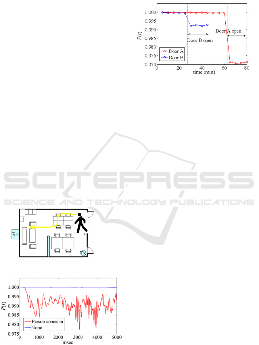
shows t
h
p
erson
p
Figure 3
B is ope
event d
e
and Oh
t
also rec
o
experim
e
Figure
1
experime
n
Figure 2
:
room.
Experime
n
Subspace
D
n
firmed the
n
method di
s
2009) throu
g
e
riment was
c
n
Figure 1. S
i
as a very
h
u
s multipath
s
e
iver. The ar
r
linear array
w
a
t a height o
f
is indicated
b
s
mitter's loca
t
t
er was 1 m
a
t
ed signal wa
s
e vector v
no
c
curred. As t
h
r
ved the cons
t
when no
t
ion period.
N
h
e result of t
h
p
ulls the doo
r
shows the r
e
e
ned. These i
n
e
tection meth
t
suki, 2009)
c
o
gnize the d
i
e
nt.
1
: Layout of
n
t.
:
Changes of
c
n
tal Result
s
D
etection
effectivenes
s
cussed in (
I
g
h experiment
c
onducted in
a
i
nce the roo
m
h
igh possibili
s
ignals betwe
e
r
ay receiver
w
w
ith a half-w
a
f
2.52 m. Th
e
b
y Rx in Fig
u
t
ion. The ant
e
a
nd the cente
r
s
2.335 GHz.
in (7) was
o
h
e blue line s
h
t
ant values o
f
event occu
r
N
ext, the red
h
e changes
o
r
B open and
e
sults when t
h
n
dicate that t
h
od discussed
c
an detec
t
s
e
i
fference of t
h
test area f
o
c
riteria when
a
s
b
y
Si
g
nal
s of the e
I
keda, Tsuji,
a
l results.
a
7×9 m roo
m
m
had metal
w
ty of gener
a
e
n the trans
m
w
as an 8-ele
m
a
velength ele
m
e
array recei
v
u
re 1. Tx indi
c
e
nna height o
f
r
frequency o
f
o
btained whe
n
h
ows in Figu
r
f
the criteria g
r
red during
line in Figu
r
o
f criteria wh
e
enters the r
o
h
e door A or
d
h
e signal subs
p
in (Ikeda,
T
e
veral events
h
e events vi
a
o
r event dete
c
a
person enter
s
Door B
Door
A
l
e
vent
and
m
, as
w
alls,
a
ting
m
itter
m
ent
m
ent
v
er’s
c
ates
f
the
f
the
n
no
r
e 2,
g
iven
the
u
re 2
en a
o
om.
d
oor
p
ace
T
suji,
and
a
the
ction
s
the
3
Si
m
the
me
t
ma
k
uni
n
b
a
n
int
e
aff
e
the
of
co
n
p
ro
b
or
d
int
e
the
alt
e
an
d
usi
n
Ko
s
3.
1
Cy
c
ch
a
cy
c
sch
alg
o
sel
e
sig
n
(G
a
sta
t
wit
h
sta
t
In
a
Figure 3: Cha
n
CYCL
O
EVEN
T
METH
O
m
ilar to the co
approach
o
t
hod in (Ike
d
k
e an inco
r
n
tentional in
t
n
d impinges
o
e
rference sig
n
e
ct the signal
array anten
n
unknown
n
sidered. One
b
lem is to a
p
er to separ
a
e
rference. Th
i
circuit size t
e
rnative appr
o
d
offers good
n
g the s
i
s
hikawa, and
1
Arra
y
c
lostationarit
y
a
racteristics.
c
lostationarity
eme and spe
e
o
rithm and C
y
e
cting signal
s
n
al arrival, h
a
a
rdner, 1994)
(
t
istics of up t
o
h
conventio
n
t
istics, the ne
c
a
ddition, sinc
n
ges of criteria
w
O
STATIO
N
T
DETEC
T
O
D
n
ventional e
v
o
f the sign
a
d
a, Tsuji, an
d
r
rect decisi
o
t
erference wi
t
n
array senso
n
als with di
ff
subspace of
t
a. Therefore,
interference
possible sol
u
ply a spread
a
te the desi
r
i
s technique,
o
expand an
d
o
ach that is c
detection pe
r
gnal’s cyc
l
S
uzuki, 2011
)
Signal C
yc
y
indicate
s
Most mod
u
characteri
z
e
d. Such tec
h
y
clic MUSIC
,
s
and estim
a
v
e received a
t
(
Gardner, 198
o
the second
n
al methods
c
essary calcu
l
e
signals can
when door is o
p
N
ARY-B
A
T
ION
v
ent detection
a
l subspace
d
Ohtsuki, 2
0
o
n if inten
t
t
h the same
f
o
rs. This is b
e
f
ferent incide
n
the received
mitigation t
e
signals sh
u
tion to deal
spectrum tec
h
r
ed signals
f
howeve
r
,
m
d
drive up co
s
c
omputational
l
r
formance is
p
l
ostationarity
)
.
c
lostationa
r
s
certain
u
lation sign
a
z
ed by
m
h
niques as th
e
,
which form
b
a
ting the dir
e
t
tention in re
c
8
8). These me
rank. Thus,
c
s
using hig
h
l
ation is rath
e
be selected
a
p
ene
d
.
A
SED
methods,
detection
0
09) may
t
ional or
f
requency
e
cause the
n
t angles
s
ignals at
e
chniques
o
uld be
with the
h
nique in
f
rom the
m
ay cause
s
ts. Here,
l
y simple
p
roposed,
(Tsuji,
r
it
y
signal
a
ls show
m
odulation
e
SCORE
b
eams by
e
ction of
c
ent years
t
hods use
c
ompared
h
er rank
e
r limited.
a
ccording
Improving Interference Immunity of Spatial Event Detection Systemusing Array Antenna
107

to differences in modulation scheme and modulation
speed, this technique can be applied to signals of a
frequency band in which a variety of modulation
schemes and speeds exist. Here, we propose utilizing
the cyclostationarity of the signal for the event
detection system in order to improve performance in
immunity against interference.
3.2 Cyclostationarity:
It is recognized that signal has a spectrum
correlation with a cyclic frequency of
, unless the
cyclic auto-correlation function of (8) is constantly
zero.
*2
22
jt
xx
rxtxte
(8)
where
indicates infinite time averaging. The
covariance matrix of the signal received by the array
antenna can be defined as shown below, based on
the cyclic correlation function:
2
22
Hjt
xx
tte
Rx x
(9)
As previously reported in multiple studies, most
modulation signals (e.g., AM, PSK, PAM, FSK)
feature
0
xx
r
at a certain cyclic frequency
and lag
; where the value of
changes with the modulation
scheme and the modulation speed. Thus, even if
other signals are included in the time and frequency
areas of the received signal, the cyclic covariance
function can be used to select the desired wave.
If we choose
to be a cyclic frequency of only the
desired signal
s(t), then we have from (9)
H
xx ss
r
R
aa
(10)
*2
22
jt
ss
rstste
The matrix (10) is obviously a rank-one matrix and
the right (or left) eigenvector associated with its one
eigenvector is
a' (or a'
H
).
3.3 Cyclostationarity-Based Event
Detection Method
The characteristics of the interference signals with
the same frequency band are unknown. Meanwhile
we can purposefully generate a transmitting signal as
the desired signal with a specified cyclic frequency.
As mentioned in 3.2, the cyclic frequency is
determined with the modulation scheme and speed.
This means we know the cyclic frequency of the
desired signal in advance and the cyclic frequency
can be used for discriminating between the desired
signal and the interference. The proposed method’s
concept is simple. In the proposed method, the cyclic
covariance function is used to distinguish the desired
signal from the interference. The covariance matrix
in (4) can be replaced by the cyclic covariance matrix
in (10). Then the eigenvector of the cyclic covariance
matrix is used to define the following new criterion
for detecting events as
no ob
H
Pt t vv
(11)
where
no
v
is the eigenvector obtained in advance
when no event occurs and
ob
v
is the eigenvector
obtained by the signals during the period under
observation, as in the original event detection method.
Even if the interference with different cyclic
frequency than the desired signal impinges on the
array, the signal subspace obtained from the cyclic
covariance matrix remains the same. Therefore, the
event detection method with the cyclostationarity of
the desired signal is performed by comparing the
value of the criterion in (11) with a specified
threshold
th
()Pt
. Note that the criterion defined in
(11) becomes identical to that in (7) if the cyclic
frequency is set at zero.
Thus, the event detection method proposed here can
be summarized as follows:
1.
Choose
to be a cyclic frequency of the
desired signal.
2.
Calculate the eigenvector
no
v
of
()
xx
t
R
when no event occurs.
3.
Update the value of
()Pt
with
ob
v
obtained
by the array.
4.
If
th
() ()Pt P t
, an event is to be expected.
5.
Repeat steps 3 and 4.
3.4 Simulation Results
Numerical examples were performed to evaluate the
proposed method’s effectiveness. The linear array
consists of eight isotropic sensors spaced uniformly,
having half the carrier wavelength. Unless otherwise
specified, signal power is given in dB SNR (signal-
to-noise ratio) and the noise is additive white
Gaussian noise (AWGN) uncorrelated from sensor
to sensor. The source signal is a BPSK signal, which
is filtered using a square root raised cosine filter
with a roll-off factor of 0.5. The three total coherent
signals with different angles (
=10°, 60°, and 20°)
First International Conference on Telecommunications and Remote Sensing
108
and SNRs (0dB,
10dB, and 10dB) impinge on the
array, and an AM interference of compatible
bandwidth arrives from
20° in the middle of the
observation period (t=100). Each symbol rate of the
BPSK signals is 0.2, which is normalized by the
sampling frequency. Therefore, the cyclic frequency
of the desired signal can be determined as 0.2. In
this case, the interference has different cyclic
frequency from the desired signals. The proposed
method is conducted with
= 0.2 and
= 0. The
event detection method studied in (Ikeda, Tsuji, and
Ohtsuki, 2009) is also performed for comparison
with the proposed method.
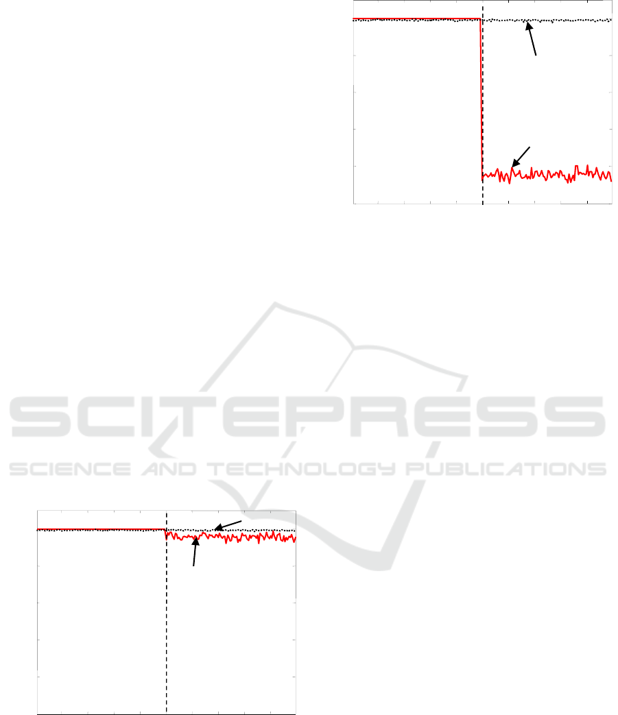
In the first simulation example, the SNR of the
interference is set at 5 dB. The resulting values of
the criteria defined in (7) and (11) are shown in
Figure 4. We observe that the value of the criteria
given by (11) stays roughly constant during the
observation period while the value obtained by (7)
decreases slightly after the interference comes in at t
=100.
In the second simulation, the SNR of the
interference is set at 10 dB and the other simulation
conditions are the same as in the first one. We
observe that the interference provides significant
change of the criterion in (7) but has little influence
on the value in (11) in Figure 5.
These results show that the proposed detection
method utilizing the cyclostationarity of the desired
signal is effective for improving immunity against
interference with different cyclic frequency.
Figure 4: Changes of criteria (interference SNR=5dB).
Figure 5: Changes of criteria (interference SNR=10dB).
4 UTILIZATION OF THE
TRANSMISSION CONTROL
SCHEME BASED ON SHORT
RANGE WIRELESS SYSTEM
Here, another approach that is structurally-simple
and offers good detection performance is proposed
using the transmission control scheme based on an
IEEE standard for short range wireless system.
We consider that CSMA/CA technique is of use
in the differentiation between desired and
interference signals. We take particular note of the
IEEE 802.15.4 standard which uses CSMA/CA. The
reason is that the systems based on the standard such
as ZigBee has few analog stages and uses digital
circuits wherever possible and that the software is
designed to be easy to develop on small and
inexpensive microprocessors. And that it is
relatively easy to detect the timing of receiving of
the desired signal from an IEEE 802.15.4 compliant
RF transceiver chip.
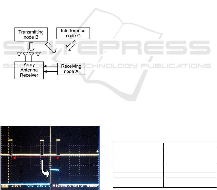
Figure 6 shows a simplified block diagram of the
equipment of the event detection system proposed
here. The receiver with an array antenna is
connected with a node terminal A, which receives
the signal from the other node terminal B. The node
terminal B knows the address of the node terminal A
and sends packets periodically to the node terminal
A. The array antenna of the receiver receives the
signals from the node B and also may receive
unknown interference occasionally. The node
terminal A connected to the receiver gives the
timing of the receiving period and the result of
receiving the desired packets if the node terminal A
time
Interference (5 dB)
1
0.8
0.6
0.4
0.2
0
20
40
60
80
100 120 140 160 180
P(t)
P(t)
P(t)
~
20 40 60 80
100
120
140 160 180
0
0.2
0.4
0.6
0.8
1
time
Interference (10 dB)
P(t)
P(t)
P(t)
~
Improving Interference Immunity of Spatial Event Detection Systemusing Array Antenna
109
receives
interfere
scheme,
transmit
t
4.1
We are
confirm
The eq
u
and is
c
based o
n
node te
r
receives
b
it after
the rece
i
p
aper,
w
receivin
g
and inte
r
terminal
meanwh
interfere
p
acket a
t
Figure 6:
detection
As
s
receivin
g
frame d
e
that it
o
delimite
r
Figu
r
F1
(Inte
the desire
d
nce. As the
the array a
n
t
ed signals fr
o
Experime
n
developing
the effective
n
u
ipment has
fo
c
onnected to
n
IEEE 802
.
r
minal is pro
g
a start of fra
m
the cyclic re
i
ved signal is
v
w
e show only
g
node termi
n
r
ference sign
a
sends a pa
c
h
ile another
t
nce with di
f
t
48 msec int
e
:
Block diagra
m
system
s
hown in Fi
g
g
node A o
u
e
limiters (F1,
o
utputted a b
i
r
packet (F2)
w
r
e 7: Start of fr
a
48 msec
rference)
F
2
d
signal suc
c
result of i
m
n
tenna receiv
o
m the other s
n
tal Result
s
an evaluati
o
n
ess of MA
C
fo
ur received
the receivi
n
.
15.4 standar
d
g
rammed to
m
e delimiter
a
dundancy ch
e
v
erified. Due
a result of t
h
n
al when it re
c
a
ls where the
c
ket at 100
m
t
ransmitting
n
f
ferent node
e
rval.
m
of the equi
p
g
ure 7, we
o
u
tputted bits
w
F2 and F3)
w
i
t (C2) only
i
w
as received
a
me delimiter
b
C2
2
F3
(Interf
e
c
essfully wit
h
m
plementing
er can avoid
y
stems.
s
o
n equipmen
t
C
-
b
ased appr
o
antenna ele
m
n
g node ter
m
d
. The recei
v
set a bit wh
e
a
nd to set an
o
e
cksum (CR
C
to the limit o
f
h
e behavior o
f
c
eives the de
s
transmitting
n
m
sec interval
n
ode termin
a
address sen
d
p
ment of the
e
o
bserved that
w
hen the sta
r
w
ere received
i
f the start f
r
from the nod
e
b
it and CRC bi
t
e
rence)
hout
the
d
the
n
t to
o
ach.
m
ents
m
inal
v
ing
e
n it
o
ther
C
) of
f
the
f
the
s
ired
n
ode
and
a
l as
d
s a
e
vent
the
r
t of
and
r
ame
e
B.
t
5
An
sys
t
det
e
rea
l
int
r
be
spe
Ta
b
sh
o
ant
e
wh
i
rec
e
als
o
co
n
to
t
the
co
n
the
rec
e
of
t
eas
i
sch
6
Th
i
the
det
e
det
e
of
t
sch
Th
e
sig
n
ant
e
fut
u
co
n
the
T
a
N
N
DEVE
L
DETE
C
evaluation
e
t
em was dev
e
e
ction. The e
q
l
-time algorit
h
r
oducing seve
possible to
u
cifications o
f
b
le 1, and t
h
o
wn in Figure
e
nna signal
t
i
ch is used
e
iving circuit
o
included in
n
nection to co
n
t
ake data fro
m
features of
t
n
nect to the n
start of fr
a
e
iving trans
m
t
he received s
i
ly enables
emes of inter
f
CONC
L
i
s paper prop
o
co-channel
i
e
ction syste
m
e
ction schem
e
t
he desired s
i
eme defined
e
proposed m
e
n
al from the
e
nna without
u
re work, so
m
n
firm the effe
c
equipmen
t
a
ble 1: Specific
a
Frequency
b
Reception
b
an
d
Reception l
e
N
umber of ante
n
N
umber of tran
s
p
ort
Interfac
e
Dimensio
n
L
OPMEN
T
C
TION E
Q
e
quipment o
f
e
loped to real
i
q
uipment was
h
m was impl
e
r
al kinds of
e
u
se with mos
t
f
the equipm
e
h
e appearanc
e
8. The equip
m
t
erminals an
d
for the tra
n
and the digit
a
the unit. Th
e
n
trol the digit
a
m
the unit by
a
t
he equipme
n
o
de receivin
g
me delimite
r
m
itting signal
a
i
gnal to the e
q
the imple
m
f
erence immu
n
L
USIONS
o
sed new tec
h
i
nterference i
m
m
which r
e
e
by exploiti
n
i
gnal or the
m
in wireless
p
e
thods could
i
nterference
t
major hardw
a
m
e experimen
t
c
tiveness of t
h
a
tions of the ev
e
b
an
d
d
width
e
vel
n
na input
s
mitting
e
n
s
2
T
OF EV
E
Q
UIPME
N
f
the event
ize the real-t
i
made smalle
r
e
mented in t
h
e
fforts so tha
t
t
engineers.
T
e
nt are sum
m
e
of the equ
i
m
ent has fou
r
d
one output
n
smitting si
g
t
al signal pro
c
e
unit also h
a
t
al signal pro
c
a
n external P
C
n
t is that the
g
terminal w
h
r
s informatio
and also the
quipmen
t
. T
h
m
entation o
f
u
nity.
h
niques for i
m
m
munity of
t
e
alized indo
o
n
g the cyclost
m
edium acce
s
p
ersonal area
distinguish t
h
t
hat impinges
are design c
h
t
s will be co
n
h
e total perfo
r
e
nt detection e
q
2400 MHz IS
M
600 k
H
-80 dBm to -
2
4
1
USB 2.
2
00 (W)140(
D
[mm]
E
NT
N
T
detection
i
me event
r
, and the
h
e unit by
t
it would
T
he basic
m
arized in
i
pment is
r
received
terminal
g
nal. The
c
essor are
a
s a USB
essor and
C
. One of
unit can
h
ich gives
n
of the
condition
h
is feature
f
several
m
proving
t
he even
t
o
r event
a
tionarity
s
s control
networ
k
.
h
e desired
on array
h
anges. In
n
ducted to
r
mance of
q
uipment.
M
ban
d
H
z
2
0 dBm
0
D
)
50(H)
First International Conference on Telecommunications and Remote Sensing
110

Figure
8
REF
E
Ikeda S.,
Detec
t
for
H
Com
m
Tsuji H
Cycl
o
Usin
g
the
Com
m
Fran
c
Gardner
Com
m
York.
Gardner
ESPR
I
IEEE
,
8
: Appearance
E
RENCES
Tsuji H., an
d
tion with Eige
n
H
ome or Offic
m
un., vol. E92-
B
., Koshikawa
o
stationarity–B
a
g
Signal Subsp
a
14th Wir
e
m
unications
S
c
e, 3-7, Oct. 20
1
W. A.,
m
unications an
d
W. A., 1988
I
T by exploita
t
,
vol. 76, no.7,
p
USB
Interface
of the event de
t
d
Ohtsuki T.,
2
n
vector Spanni
n
e Security, i
n
B
, no. 7, pp. 24
0
M., and
S
a
sed Spatial
a
ce of Array
A
e
less Pers
o
S
ymposium (
W
1
1.
1994, Cy
c
d
Signal Proc
e
, Simplificati
o
t
ion of cyclo-
st
p
p. 845-847.
R
Receiving
Node
400 mm
t
ection equipm
e
2
009, Indoor
E
n
g Signal Sub
s
IEICE Tran
s
06
-2412, July
2
S
uzuki M.,
2
Event Dete
c
A
ntenna, In Pr
o
o
nal Multi
m
WP
M
C'11),
B
c
lostationarity
e
ssing, IEEE,
o
n of MUSIC
t
ationarity, In
P
R
eceiving
Antenna
e
nt
E
vent
s
pace
s
. on
2
009.
2
011,
ction
o
c. of
m
edia
B
rest,
in
New
and
P
roc.
Improving Interference Immunity of Spatial Event Detection Systemusing Array Antenna
111
