
Automatic Update and Completion of Occluded Regions for Accurate 3D
Urban Cartography by combining Multiple Views and Multiple Passages
Ahmad Kamal Aijazi, Paul Checchin and Laurent Trassoudaine
Clermont Universit
´
e, Universit
´
e Blaise Pascal, UMR 6602, CNRS, 63177 Aubiere, France
Keywords:
3D Cartography, Lidar Data, Occlusions, Multiple Views, Multiple Passages.
Abstract:
Handling occlusions is one of the more difficult challenges faced today in urban landscape analysis and carto-
graphy. In this paper, we successfully address this problem by using a new method in which multiple views
and multiple sessions or passages are used to complete occluded regions in a 3D cartographic map. Two 3D
point clouds, from different viewing angles, obtained in each passage are first classified into two main object
classes: Permanent and Temporary (which contains both Temporarily static and Mobile objects) using infer-
ence based on basic reasoning. All these Temporary objects, considered as occluding objects, are removed
from the scene leaving behind two perforated 3D point clouds of the cartography. These two perforated point
clouds from the same passage are then combined together to fill in some of the holes and form a unified per-
forated 3D point cloud of the cartography. This unified perforated 3D point cloud is then updated by similar
subsequent perforated point clouds, obtained on different days and hours of the day, filling in the remaining
holes and completing the missing features/regions of the urban cartography. This automatic method ensures
that the resulting 3D point cloud of the cartography is most accurate containing only the exact and actual
permanent features/regions. Special update and reset functions are added to increase the robustness of the
method. The method is evaluated on a standard data set to demonstrate its efficacy and prowess.
1 INTRODUCTION
In the recent past, 3D urban reconstruction and Vi-
sualisation of cities have become a hot topic of re-
search in the scientific community. Several geograph-
ical navigators like Google Streetmap Viewer, Mi-
crosoft Visual Earth or Geoportail provide real-like
representation of the terrain and ground based mod-
els, created by mobile terrestrial image acquisition
techniques. However, in urban environments the qua-
lity of data acquired by these hybrid terrestrial vehi-
cles is widely hampered by the presence of temporary
stationary and dynamic objects (pedestrians, cars, etc)
in the scene. As a result there is a problem of oc-
clusion of regions. Moving objects or certain tempo-
rary stationed objects (parked cars, traffic, pedestrian
etc) present in the area hide certain zones of the ur-
ban landscape (buildings, road sides etc.). This pa-
per presents a new method for handling occlusions
and moreover automatic update and completion of oc-
cluded regions for accurate 3D urban cartography ex-
ploiting the concept of multiple views and multiple
passages.
In order to solve the problem of occlusions, diff-
erent techniques have been employed building on the
advances made in the work on texture synthesis. A
technique of inpainting based on the patch exemplar-
based technique was presented by (Criminisi et al.,
2004). This approach was extended by (Wang et al.,
2008) to also infer depth from stereo pairs. A sim-
ilar method was used by (Engels et al., 2011) for
3D data, but occlusions were found automatically us-
ing object-specific detectors making it more suitable
for larger data sets. In the context of building fa-
cades and urban reconstruction, increased contextual
knowledge is available by assuming structure’s pla-
narity and repetition of features such as floors, win-
dows, etc. Building models are reconstructed by de-
tecting floors and estimating building height in the
work of (Konushin and Vezhnevets, 2007). Occlu-
sions are removed by cloning upper floors and pro-
pagating them downward. A method relying on LI-
DAR point cloud to find and remove occlusions by
combining image fusion and inpainting is presented
by (Benitez et al., 2010). (Xiao et al., 2009) seman-
tically segment street-side scenes into several classes,
including vegetation and vehicles, but do not actively
fill in missing data. Instead, they rely on the missing
405
Kamal Aijazi A., Checchin P. and Trassoudaine L. (2013).
Automatic Update and Completion of Occluded Regions for Accurate 3D Urban Cartography by combining Multiple Views and Multiple Passages.
In Proceedings of the 2nd International Conference on Pattern Recognition Applications and Methods, pages 405-412
DOI: 10.5220/0004182704050412
Copyright
c
SciTePress

information being available from other views.
A method of aligning multiple scans from vari-
ous viewpoints to ensure the 3D scene model com-
pleteness for complex and unstructured underground
environments is discussed by (Craciun et al., 2010).
A technique for extracting features from urban buil-
dings by fusing camera and lidar data is presented by
(Becker and Haala, 2007) but it also fails to address
this problem. (Frueh et al., 2004) proposed a method
in which the point cloud is used to generate a 3D mesh
that is then classified as foreground or background.
Large holes in the background layer, caused by oc-
clusions from foreground layer objects, are then filled
by planner or horizontal interpolation. However, such
an approach may result in false features in case of in-
sufficient repetitions or lack of symmetry (Li et al.,
2011). In our work, we aim to resolve this problem
by using a new approach combining both multiple
views and multiple passages such that first multiple
views are exploited to fill in some of the holes in the
3D point cloud followed by the use of multiple scans
of the same environment obtained at different days
and hours of the day to fill in the remaining holes and
completing the missing regions of the urban cartogra-
phy. This ensures that the resulting 3D point cloud
of the cartography is most accurate containing only
the exact and actual permanent features/regions. An
overview of the method is presented in Algorithm 1.
2 3D SCAN REGISTRATION
Different features and robust landmarks extracted
from 3D images as points of interest and as refer-
ences for image mapping and scan registration have
commonly been used for different multi-sessional
SLAM (Simultaneous Localisation And Mapping) al-
gorithms. This approach works well in simple repeti-
tive paths. But some more complex situations can be
found in urban environments where the selected fea-
tures/regions can be occluded. When the data acqui-
ring vehicle enters from different directions, then the
path is not repetitive. As a result, the selected fea-
tures/regions may not be readily visible, etc. Thus,
in order to cater for this problem, the method of di-
rect geo-referencing of 3D LiDAR points is found
most suitable in our case. The method uses integrated
GPS/IMU data to directly orient laser data from its
local reference frame to the mapping reference frame
(WGS84).The advantage of using this method is that
the transformation between the local laser reference
frame and the mapping reference frame is known at
any given moment (as long as the laser is synchro-
nized), independently if the laser is collecting data
(a)
(b)
(c)
Figure 1: (a) The Vis Center’s LiDAR Truck. (b) Optech
LiDAR/GPS system along with IMU mounted on a rigid
frame. (c) The different viewing angles of the mounted Li-
DAR systems.
in a static mode or in kinematic mode. Thus, the
laser can be used as a pushbroom sensor sweeping the
scene with profiles while fixing the scan angles as the
vehicle moves.
The data that we have used to evaluate our work
are the dynamic data set of the 3D Urban Data Chal-
lenge 2011, which contains dynamic scenes from
downtown Lexington, Kentucky, USA obtained from
the Vis Center’s (University of Kentucky) LiDAR
Truck containing two Optech LiDAR sensor heads
(high scan frequency up to 200 Hz), a GPS, an iner-
tial measurement unit and a spherical digital camera
as shown in Figure 1.
3 CLASSIFICATION OF 3D
URBAN ENVIRONMENT
We classify the urban environment into 2 main ca-
tegories: Permanent objects and Temporary objects.
In order to achieve this, the 3D point cloud is first
segmented into objects which are then classified into
basic object classes. Once classified into these basic
classes, they are then grouped under one of the 2 men-
tioned categories. Although several methods have
been proposed for the classification of urban environ-
ments, we have used one of the most recent meth-
ods (Aijazi et al., 2012) for this task. This method
presents a super-voxel based approach in which the
3D urban point cloud is first segmented into vox-
els and then converted into super-voxels. These are
then clustered together using an efficient Link-Chain
method to form objects. These objects are then clas-
sified using local descriptors and geometrical features
into 6 main classes: {Road, Building, Car, Pole, Tree,
Unclassified}. The salient features of this method are
data reduction, efficiency and simplicity of approach.
The 3D point cloud obtained from each of the two
mounted LiDAR sensors is divided into the 6 object
ICPRAM2013-InternationalConferenceonPatternRecognitionApplicationsandMethods
406

Algorithm 1: Proposed method.
Input: 3D urban point clouds for passage number n
p
1: Classify 3D urban point cloud obtained from each of
the two sensors into 6 groups: {Road, Building, Car,
Pole, Tree, Unclassified}
2: Further classify the objects as: {Permanent, Temporary
}
3: Separate out Temporary objects leaving behind two
perforated 3D point clouds
4: Combine the two 3D point clouds of the two sensors
(different viewing angles) to fill in some of the holes
and obtain a unified perforated 3D point cloud P(n
p
)
5: Store Temporary objects in a register R(n
p
)
6: Match and compare P(n
p
) with P(n
p
−1) to fill in the
remaining holes and complete 3D cartography
Update:
7: Compare Temporary objects in R(n
p
) with R(n
p
−1)
8: Upgrade Temporary objects in R(n
p
) if they are re-
peated in n
update
number of passages as Permanent and
add in P(n
p
)
Reset:
9: Compare the skyline in P(n
p
) with that of P(n
p
−1) to
calculate 3D error difference
10: If same error difference re-occurs in n
reset
number of
passages then Reset the modified part of the building
in P(n
p
) with that in the recently acquired point cloud
(perforated)
11: Update and Store R(n
p
)
12: Store point cloud P(n
p
)
13: R(n
p
−1) ← R(n
p
) and P(n
p
−1) ← P(n
p
)
14: return P(n
p
)
classes using this method. These classified objects
are then further classified using inference based on
their basic characteristics (like roads, buildings, trees
and poles cannot move whereas cars and pedestrians
can be either Temporarily static or Mobile) into two
classes: {Permanent , Temporary}. The classification
chart as per our inference is presented in Table 1.
Table 1: Object classification chart.
Object type Permanent Temporary (Static or Mobile)
Road x
Building x
Tree x
Pole x
Car x
Pedestrian x
Unclassified x
Once the objects present in the urban scene are
classified into these two main classes, in each pas-
sage, the objects classified as Temporary are sepa-
rated from the scene (for each lidar) for each passage
to obtain perforated point clouds. This perforation
is due to occlusions caused by the temporarily static
and mobile objects in the scene. These two perfo-
rated point clouds (from different viewing angles) are
merged together to form a unified 3D point cloud fil-
ling in some of the holes in the process.These unified
perforated 3D point clouds of the same place obtained
via a single passage on different days and at different
times are then combined together to complete the 3D
cartography as discussed in the following sections.
As the nature of the unclassified objects is not
known, they are considered temporary by default be-
cause all the objects classified as temporary are com-
pared in update phase. If the same objects belonging
to this class are found in repeated passages, they are
then upgraded as Permanent objects in the update
phase discussed in Section 5.2 and are considered part
of the 3D cartography.
4 COMBINING MULTIPLE
VIEWS
The two 3D point clouds obtained in the same pas-
sage are matched and merged together. This not only
helps in filling some of the holes but also completes
the 3D cartography (building fac¸ades, etc.) due to the
different viewing angles of the two sensors (from now
on referred to as S −01 and S −02) as shown in Fi-
gure 1(c). This configuration of the LiDAR sensors
is very common for this type of sensors and is used
for acquiring detailed 3D data along both sides of the
road. We see that this configuration of the lidar sen-
sors not only fill in holes due to static objects present
in the scene (see Figure 5) but also those caused by
the mobile objects as due to this difference in viewing
angle these sensors see the same point in the 3D scene
with a slight time difference. This time difference al-
lows a moving object to move such that the occluded
portion of the cartography due to this object in S −01
becomes evident in S −02 while the occluded portion
in S −02 was evident in S −01. Thus, combining the
two 3D point clouds help fill up such holes in an at-
tempt to eliminate the effect of the moving object in
the scene as shown in Figure 5.
The two 3D point clouds are matched and merged
together using the new matching method introduced
in Section 5.1 to form a unified perforated 3D point
cloud. This method of fusing multiple view data to
fill in holes may be effective in simple cases but in
more complex scenarios offered in the urban envi-
ronment relying on multiple views alone does not en-
tirely solve the problem of occlusions and a number
of holes remain due to several blind spots as shown
in Figure 5 (neighborhood-2). In Figure 5(c) (clas-
sic case of occlusion caused by a temporary static
object, i.e. a parked car, present in the scene) it can
be seen that even after combining the data from mul-
tiple views, some regions of the cartography remain
AutomaticUpdateandCompletionofOccludedRegionsforAccurate3DUrbanCartographybycombiningMultipleViews
andMultiplePassages
407

occluded such as parts of shop’s wall, lamppost, tree
and road side.
Similarly for a temporary dynamic object, i.e. a
moving car present in the urban scene, combining
the data from multiple views does not fully complete
all the occluded regions as seen in Figure 5(f) (some
parts of shop’s wall and road side remain occluded).
So, this technique of combining multiple views is
helpful for completion of certain occluded regions but
does not solve the problem completely. Thus, in order
to complete the remaining exact and actual occluded
regions we use a new method exploiting the concept
of multiple passages described in the next section.
5 EXPLOITING MULTIPLE
PASSAGES
The unified perforated 3D point clouds obtained for
each passage of any particular place are combined to-
gether to fill in the remaining holes and complete the
3D urban cartography. These 3D point clouds are first
registered and then the 3D points are matched point
by point, completing the missing regions.
5.1 3D Urban Point Cloud Matching
Each subsequent 3D point cloud is registered with the
former point cloud by using the ICP method (Besl and
McKay, 1992). This method is most suitable for this
task as the 3D data are already geo-referenced and
hence lie in close proximity. It is observed that the
major part of the 3D urban point clouds is composed
of building points which are also found to be most
consistent. Thus instead of applying the ICP method
to complete 3D point clouds, only the building points
are taken into account. First the profile/envelope of
the buildings is extracted and then the ICP method
is applied, matching these boundaries to obtain the
transformation matrix. The outlines/envelopes of the
buildings are extracted using a sweep scan method.
As the bottom part of the building outline close to
the ground is often occluded and hence inconsistent
due to the presence of different objects in the scene,
only the boundary of the top half of the building out-
line is subjected to ICP as shown in Figure 2.
Once the transformation matrix (rotation matrix
R
m
and translation matrix T
m
) is found, the whole 3D
point cloud P(n
p
) is transformed into P
0
(n
p
) and then
registered with the former P(n
p
−1) using (1).
P
0
(n
p
) = R
m
(P(n
p
)) + T
m
(1)
In order to avoid redundant points a union of 3D
points belonging to the two registered point clouds
Figure 2: In red and blue color we have the building outline
obtained from first passage. In green and black we have the
building outline obtained from the second passage. Only
top half of the two outlines in blue and black respectively is
subjected to ICP.
is performed. Each 3D point of the first cloud is
matched with that of the second cloud. Two corres-
ponding points match if (2) is satisfied:
|
p
Oa
−p
Ob
|
≤
3
√
e
tol
(2)
where p
Oa
and p
Ob
(3 ×1 vectors) are point positions
in the two point clouds along X, Y and Z axes. e
tol
(3 ×1 vector) is equal to the inverse of the maximum
number of 3D points per cubic meter that is desired in
the 3D cartographic map. The matched 3D points are
considered as one point. This ensures that only the
missing points are added completing the perforated
3D point cloud.
5.2 Update Phase
With every new passage, where the urban cartogra-
phy is completed, the objects classified in each pas-
sage as Temporary are analyzed. If the same objects
belonging to this class are found at the same place in
repeated passages, they are then upgraded as Perma-
nent objects and are considered part of the 3D car-
tography (see Algorithm 1). They are then added to
the 3D cartography. Otherwise non-repetitive objects
are deleted from the update register R(n
p
). This num-
ber of allowable repetitions n
update
can be fixed, based
upon the frequency of repetition, time of repetition,
etc. This not only allows gradual update of the 3D car-
tography but also accommodates unclassified objects
in the scene; for example, in case of neighborhood-1
(see Figure 7), a few unclassified dustbins/trashcans
were added to the cartography, after repetition in the
successive passages, during update phase.
The Temporary objects in each passage are com-
pared with the objects present in the update register
R using the equations (3), (4) & (5). Simple match-
ing based on constituting points, color and intensity is
enough. Let P
Obj
n
and Q
Obj
n
be the two set of points
belonging to an object n in the update register R and
the new passage respectively. This Obj
n
is considered
to be repeated if only, and only if, the following three
ICPRAM2013-InternationalConferenceonPatternRecognitionApplicationsandMethods
408
conditions are satisfied:
Card(PQ
Obj
n
)
Card(min[P
Obj
n
, Q
Obj
n
])
×100 ≥w
p
(3)
|
P
Obj
nR,G,B
−Q
Obj
nR,G,B
|
≤ 3
√
w
c
(4)
|
P
Obj
nI
−Q
Obj
nI
|
≤ 3
√
w
I
(5)
where PQ
Obj
n
= P
Obj
nX,Y,Z
∩Q
Obj
nX,Y,Z
. PQ
Obj
n
is the set
containing the matched points obtained by point wise
intersection of the 3D points in the two sets if, and
only if, the difference in the distance along X, Y & Z
axes between two points in the P
Obj
nX,Y,Z
and Q
Obj
nX,Y,Z
is ≤ 2 ×P
e
.
Here P
e
is taken as the measurement accuracy
of the LiDAR sensor (value can be obtained from
data sheet) and Card is the cardinal number function.
P
Obj
nX,Y,Z
and Q
Obj
nX,Y,Z
are the sets of the 3D coordi-
nates of the points of the object while P
Obj
nR,G,B
and
Q
Obj
nR,G,B
are the mean R,G & B values of the object
in P and Q point clouds respectively. P
Obj
nI
and Q
Obj
nI
are the mean laser reflectance intensity values in P
and Q point clouds respectively. w
p
is the matching
weight equal to the allowable percentage of the object
points whose position matches the two point clouds.
w
c
is the color weight equal to the maximum vari-
ance of R,G & B values for P
Obj
n
and Q
Obj
n
. w
I
is
the intensity weight equal to the maximum variance
of intensity values for P
Obj
n
and Q
Obj
n
.
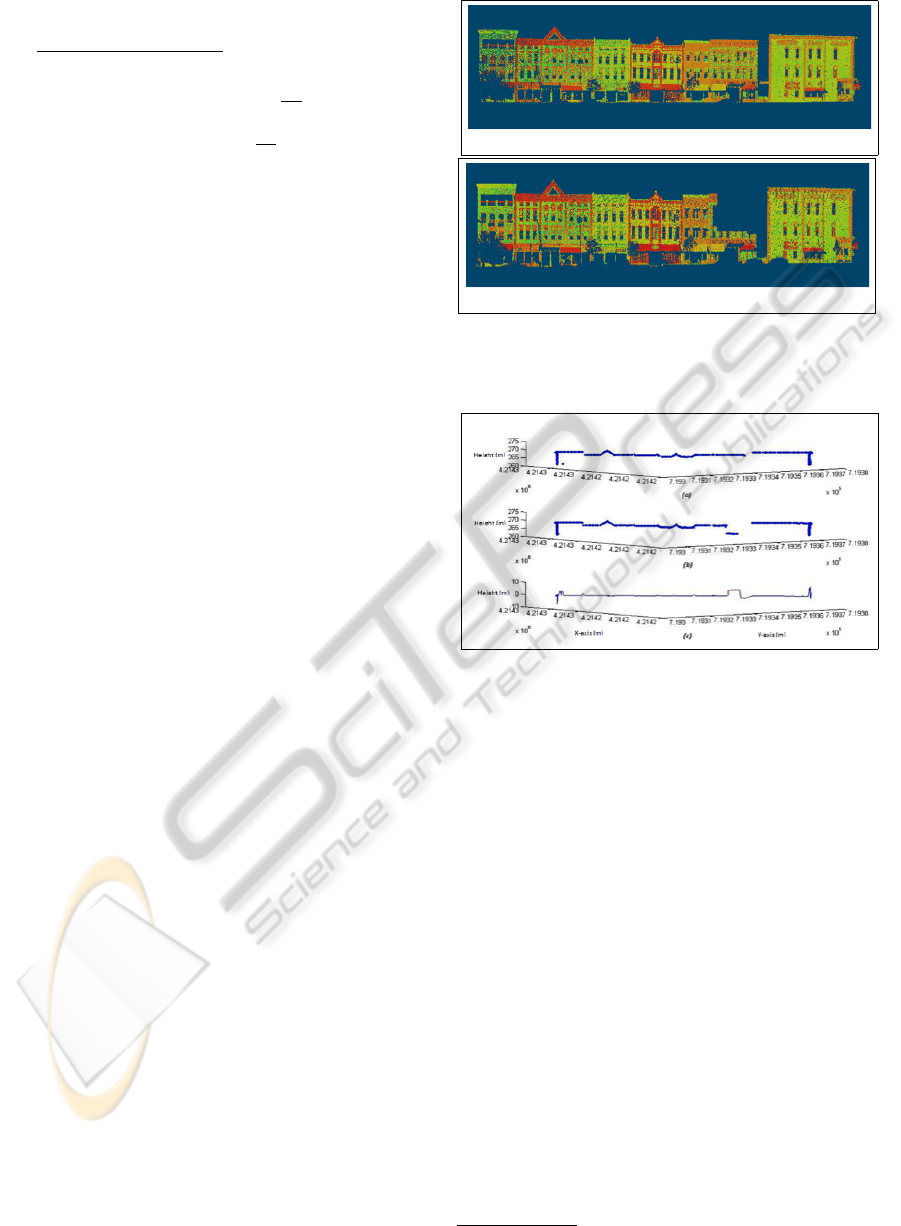
5.3 Reset Phase
In case of a building or some part of a building is de-
molished in the 3D cartography due to renovation or
reconstruction then the 3D point cloud is reset with
the most recently acquired point cloud (perforated).
In such a case, it is assumed that the removal of com-
plete building or part of it causes a change in the sky-
line (or top part of the profile). This change is de-
tected by comparing the skyline in the most recently
acquired point cloud with that of the former. The
3D error difference of the two skylines is analyzed as
shown in Figure 4. If the same error difference (∆x, ∆y
and ∆z in length, width and height respectively are
greater than pre-defined thresholds) re-occurs in sub-
sequent n
reset
number of passages then only the modi-
fied part of the building in the 3D point cloud is reset
(column width and thickness equal to the error size
along respective axis and height equal to the building
height) with that in the recently acquired point cloud
(perforated). The proposed reset method was verified
by synthetically removing/demolishing different parts
of the buildings in the 3D cartography as shown in Fi-
gure 3. In Figure 4, the skylines in the two 3D point
clouds and the 3D error difference are shown.
(a)
(b)
Figure 3: (a) shows the building in the first 3D point cloud.
In (b) demolished building in the subsequent 3D point cloud
is presented.
Figure 4: The skylines in the two 3D point clouds are re-
spectively shown in (a) and (b). In (c) the 3D error of the
two skylines is presented.
6 RESULTS
In order to validate our method, the dynamic data set
of the 3D Urban Data Challenge 2011
1
was used.
This data set contains 4 sets of the same dynamic
scenes of downtown Lexington, Kentucky, USA ob-
tained on different days and at different times. The
data set consists in 3D points coupled with correspon-
ding laser reflectance intensity values. As the corres-
ponding RGB values are not readily available, (3) was
not used. This did not have much impact on the results
as laser reflectance values is found to be more consis-
tent than RGB values in an urban environment as it is
more illumination invariant (Aijazi et al., 2012). The
results of our method applied to two different neigh-
borhoods are discussed in this paper. In Figure 7,
the detailed results for neighborhood-1 are presented.
The value of w
p
= 75 (i.e. if more than 75% of the
object’s 3D points in the two point clouds match),
1
http://www.vis.uky.edu/3dimpvt/
AutomaticUpdateandCompletionofOccludedRegionsforAccurate3DUrbanCartographybycombiningMultipleViews
andMultiplePassages
409
(a) 3D points from S −01 (b) 3D points from S −02 (c) Combined 3D point clouds
(d) 3D points from S −01
(e) 3D points from S −01
(f) Combined 3D point clouds
Figure 5: In (a), (b) and (c) the filling of holes due to the presence of a temporarily static (parked) car by multiple view
combination is presented. In (d), (e) and (f) the filling of holes due to the presence of a temporary (dynamic) car by com-
bining multiple views, is presented. It can be seen in (c) and (f) that even after combining data from multiple views, some
holes/missing regions still remain due to blind spots.
Table 2: Classification results for permanent objects (F
1
-
Score).
Neighborhood
Passage Combining
1 2 3 4 multiple passages
1 0.943 0.977 0.958 0.959 0.981
2 0.979 0.975 0.981 0.984 0.992
e
tol
= (0.000125 0.000125 0.000125)
T
(in m
3
) and
n
update
= 4 (maximum number of passages possible in
our case) was used to evaluate our results.
6.1 Evaluation and Discussion
In order to obtain a more comprehensive analysis,
firstly, the classification results were evaluated for
all passages individually and then for the proposed
method of multiple passages using F-measure (see
(6)) as described by (Hripcsak and Rothschild, 2005).
F
β
= (1 + β
2
)
p.r
(β
2
. p + r)
(6)
where p and r are the precision and recall respectively
and β is the weight constant. The classification results
of Permanent object type for neighborhood 1 and 2
are presented in Table 2. Constituting the permanent
cartography, they are of most interest to us whereas
all other object types are removed from the final 3D
point cloud. The value of β = 1 was used to obtain
a balanced F
1
score. The classified objects were con-
sidered as a percentage of their constituting points in
the 3D scene. The Table 2 shows that the proposed
method also improves the classification results.
Thus the proposed technique, independent of the
initial classification method used, ensures that the per-
manent objects in the 3D urban scene are well charac-
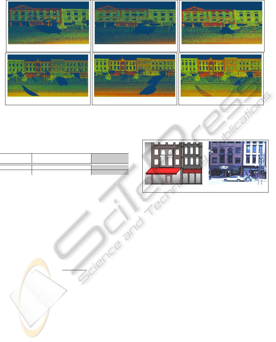
(a) (b)
Figure 6: (a) shows the generated 3D model of the buildings
according to dimensions. In (b) one of the camera images
of the building is presented.
terized/extracted for further processing and cartogra-
phy.
In order to evaluate the accuracy of the completed
permanent features/regions, we selected a corner buil-
ding in neighborhood-1. As no ground truth was read-
ily available, we generated the ground truth by cre-
ating a simplified 3D model of the building using a
standard CAD software as shown in Figure 6. The
3D points from the initial acquisition were used for
this purpose while the missing features/regions were
completed by horizontal and vertical interpolation,
exploiting the symmetry of the building design, and
confirmed/matched with the images of the building,
from different viewing angles, acquired by the digi-
tal spherical camera mounted on the vehicle (see Fi-
gure 6). A number of features/regions including the
occluded zones were selected for comparison. The di-
mensions of these selected features updated and com-
pleted in the 3D point cloud obtained at each passage,
using our method, was then compared with their cor-
responding dimensions in the ground truth. The ave-
rage absolute errors in X , Y and Z (height) axes of
the available dimensions obtained in each passage are
ICPRAM2013-InternationalConferenceonPatternRecognitionApplicationsandMethods
410
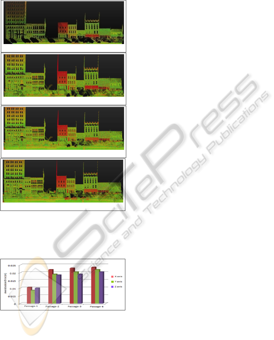
(a) 3D point cloud P(n
p
): after 1
st
passage
(b) 3D point cloud P(n
p
): after 3
rd
passage
(c) 3D point cloud P(n
p
): after 4
th
passage
(d) 3D point cloud P(n
p
): after update phase
Figure 7: (a) shows the initial point cloud related to urban
cartography, full of holes due to occlusions. Completion
of occluded and missing regions in the urban cartography,
exploiting the concept of multiple passages are presented in
(b) & (c). (d) shows the updated point cloud after update
phase.
Figure 8: Average absolute errors in X, Y and Z (height)
directions.
presented in Figure 8. These error values include both
registration and sensor measurement errors. Low ave-
rage absolute error values obtained for passage-1 are
due to the fact that part of these 3D points was used
for ground truth generation.
Generally, these fairly constant error values are
acceptable for most applications, it is observed that
the average absolute error values increase slightly in
subsequent passages due to the fact that registration
errors add up in every passage.
7 CONCLUSIONS
In this work, we present a new method for 3D urban
cartography that successfully addresses the difficult
problem concerning the automatic update and com-
pletion of occluded regions in the urban environment
by combining both multiple views and multiple pas-
sages. The proposed method ensures that the result-
ing 3D point cloud of the cartography is most accu-
rate that it contains only the exact and actual perma-
nent features/regions. The evaluated results demon-
strate the technical prowess of the proposed method
which can be easily integrated in different commercial
and non-commercial applications pertaining to urban
landscape modeling and cartography that need to up-
date their database frequently.
ACKNOWLEDGEMENTS
This work is supported by the French national re-
search agency (ANR CONTINT iSpace&Time –
ANR-10-CONT-23) and by “le Conseil G
´
en
´
eral de
l’Allier”. The authors would like to thank Prof.
Ruigang Yang for providing access to the 3D Urban
Data Challenge data set.
REFERENCES
Aijazi, A. K., Checchin, P., and Trassoudaine, L. (2012).
Classification of 3D Urban Scenes – A Voxel Based
Approach. In Int. Conf. on Pattern Recognition, Ap-
plications and Methods, Vilamoura, Portugal.
Becker, S. and Haala, N. (2007). Combined Feature Extrac-
tion for Fac¸ade Reconstruction. In ISPRS Workshop
on Laser Scanning and SilviLaser, page 44, Espoo,
Finland.
Benitez, S., Denis, E., and Baillard, C. (2010). Automatic
Production of Occlusion-Free Rectified Fac¸ade Tex-
tures using Vehicle-Based Imagery. In Photogrammet-
ric Computer Vision and Image Analysis, page A:275.
Besl, P. and McKay, N. (1992). A Method for Registration
of 3-D Shapes. In IEEE Trans. on Pattern Analysis
and Machine Intelligence, volume 14(2), pages 239–
256, USA.
Craciun, D., Paparoditis, N., and Schmitt, F. (2010). Multi-
view scans alignment for 3D spherical mosaicing in
large-scale unstructured environments. Computer Vi-
sion and Image Understanding, 114(11):1248 – 1263.
AutomaticUpdateandCompletionofOccludedRegionsforAccurate3DUrbanCartographybycombiningMultipleViews
andMultiplePassages
411

Criminisi, A., P
´
erez, P., and Toyama, K. (2004). Region fil-
ling and object removal by exemplar-based inpainting.
IEEE Trans. Image Processing, 13(9):1200–1212.
Engels, C., Tingdahl, D., Vercruysse, M., Tuytelaars, T.,
Sahli, H., and Van Gool, L. (2011). Automatic oc-
clusion removal from fac¸ades for 3D urban recons-
truction. Advanced Concepts for Intellig. Vision Sys-
tems, pages 681–692.
Frueh, C., Sammon, R., and Zakhor, A. (2004). Auto-
mated texture mapping of 3D city models with oblique
aerial imagery. In Proc. of 2nd Int. Symp. on 3D Data
Processing, Visualization and Transmission (3DPVT),
pages 396–403. IEEE.
Hripcsak, G. and Rothschild, A. S. (2005). Agreement, the
F-Measure, and Reliability in Information Retrieval.
Journal of American Medical Iinformatics Associa-
tion, 12(3):296–298.
Konushin, V. and Vezhnevets, V. (2007). Automatic buil-
ding texture completion. In Proc. Graphicon’2007,
Moscow, Russia.
Li, Y., Zheng, Q., Sharf, A., Cohen-Or, D., Chen, B., and
Mitra, N. J. (2011). 2D-3D Fusion for Layer Decom-
position of Urban Facades. In IEEE Int. Conf. on
Computer Vision (ICCV), Barcelona, Spain.
Wang, L., Jin, H., Yang, R., and Gong, M. (2008). Stereo-
scopic inpainting: Joint color and depth completion
from stereo images. In IEEE Conf. on Computer Vi-
sion and Pattern Recognition (CVPR), pages 1–8.
Xiao, J., Fang, T., Zhao, P., Lhuillier, M., and Quan, L.
(2009). Image-based street-side city modeling. ACM
Trans. Graph., 28:114:1–114:12.
ICPRAM2013-InternationalConferenceonPatternRecognitionApplicationsandMethods
412
