
Towards a Dynamic Tibial Component for Postoperative
Fine-tuning Adjustment of Knee Ligament Imbalance
Andrea Collo
1,2,3
, Shaban Almouahed
1,2
, Chafiaa Hamitouche
1,2
, Philippe Poignet
3
and Eric Stindel
2,4
1
Institut Mines-Télécom, Télécom Bretagne, Brest, France
2
Laboratoire de Traitement de l'Information Médicale, LaTIM INSERM UMR 1101, Brest, France
3
Laboratoire d'Informatique, de Robotique et de Microélectronique de Montpellier,
LIRMM UMR 5506 CNRS UM2, Montpellier, France
4
Centre Hospitalier Universitaire de Brest, CHU Brest - Service d'Orthopédie et de Traumatologie, Brest, France
Keywords: Instrumented Tibial Component, Adaptive Knee Prosthesis, Knee Ligament Imbalance.
Abstract: During TKA surgery, a correct tibiofemoral alignment of the installed prosthesis can be effectively achieved
by means of Computer-Assisted techniques. Unfortunately, the achievement of perfect ligament balance
conditions still remains as unsolved problem. Any inaccuracy during the operation may degenerate and lead
to prosthesis failure. Our aim is to develop an adaptive knee prosthesis, able to follow the physiological
evolution of the body and, potentially, to modify its shape to fit the patient's morphological changes. In this
paper, we focus on the actuation of the tibial component in order to compensate for collateral ligament
imbalances. We face with severe constraints concerning the available volume, the high-accuracy level and
system's solidity and biocompatibility. We discuss a model that we proposed in a previous work and we
highlight its drawbacks. We consider then three possible approaches to realise the actuation: the use of a
micromotor, the action of a magnetic field and the use of an external tool. After evaluating the pros and cons
of each case, the micromotor approach is selected. We conclude by introducing an original design of
adaptive tibial implant that we are currently developing.
1 INTRODUCTION
Total Knee Arthroplasty (TKA) consists in the
complete replacement of the knee joint by means of
a prosthesis. This operation is quite risky and
complicated, since the surgeon must be able to
restore the perfect mobility of the knee joint while
ensuring, at the same time, a long-lasting stability of
the installed implant. The outcome of TKA surgery
is thus greatly dependent on the surgeon's experience
and perception (Scuderi and Tria, 2006).
The two key achievements of TKA surgery are
the correct alignment of the prosthesis with respect
to the mechanical axis of the lower limb and the set
up of a proper tension for medial and lateral
ligaments (Vail and Lang, 2006). While a correct
tibiofemoral alignment can be effectively achieved
by means of Computer-Assisted Orthopaedic
Surgery (CAOS) techniques, the inaccuracy in
ligament balance still remains as unsolved problem
(Winemaker, 2002).
Concerning medial and lateral ligaments, the
tensioning conditions that are set up during the
surgery will not fit the predictable changes in
patient's weight, physiology and lifestyle. Thus,
throughout the first decade after the intervention,
knee balance conditions could become suboptimal,
leading to postoperative complications.
In this context, even the slightest inaccuracy in
the bone cutting process during the surgery may be
amplified and create serious complications, such as
component loosening and polyethylene early wear
(Almouahed, 2011). Undesired distances between
the prosthetic components can be generated and
collateral ligament tension values might change in
an uncontrolled way. As a consequence, the lifespan
of the installed implant risks being considerably
reduced and the patient may start suffering severe
pain already a few years after the surgery. In such a
case, the only solution is represented by revision
surgery. The patient undergoes a second operation
during which the prosthesis that has become
suboptimal is replaced by another one.
If primary TKA is a very complex operation,
revision surgery is even more delicate. The
95
Collo A., Almouahed S., Poignet P., Hamitouche C. and Stindel E..
Towards a Dynamic Tibial Component for Postoperative Fine-tuning Adjustment of Knee Ligament Imbalance.
DOI: 10.5220/0004189000950102
In Proceedings of the International Conference on Biomedical Electronics and Devices (BIODEVICES-2013), pages 95-102
ISBN: 978-989-8565-34-1
Copyright
c
2013 SCITEPRESS (Science and Technology Publications, Lda.)
prosthetic knee articulation undergoing a
postoperative complication is less strong than before
and the second rehabilitation period is normally
more stressful than the first one. The development of
an autoadaptive knee prosthesis, able to follow the
physiological evolution of the body and, potentially,
to modify its shape to fit the patient's morphological
changes would represent a great innovation in the
field of orthopaedic surgery.
Our project falls within this framework. Our
objective is to develop an instrumented tibial
component to be employed in both the intraoperative
and postoperative periods. It is meant to be able to
check knee balance conditions immediately after the
rehabilitation stage and correct potential ligament
imbalances. In this sense, the active implant we are
developing necessarily embeds custom-designed
mechatronical components and a telemetry system,
in order to interact with the surgeon via a computer
interface.
The main constraints we face with are of
different nature. First, considering the small
dimensions of prosthetic parts, we need very
compact components. Secondly, the entire system
needs to be really robust, in order to face with the
whole set of efforts acting on the knee joint. Thirdly,
we must choose the optimal power supply and
control techniques in order to ensure a high accuracy
level. All these considerations have to be made by
keeping the biocompatibility issue as a basic
criterion for the selection of proper components.
1.1 State of the Art
Marmignon et al., (2004) proposed two models of
instrumented knee distractor for intraoperative use.
The first one consisted of a tibial baseplate and two
separated femoral plates. Two scissor jack
mechanisms, each one controlling the position of a
single femoral plate, allowed to raise or lower the
two moving trays independently, by keeping them
parallel to the surface of the tibial baseplate (Figure
1). The upper surfaces of the two femoral
components, in contact with the femoral condyles,
were equipped with force-sensing resistances and
height sensors. By making use of a navigation
system, tibiofemoral gaps, ligament lengths and
distraction forces could be intraoperatively measured
and monitored with high accuracy.
The device's overall thickness measured 6.1 mm
and it could provide a remarkable distraction range
of 15 mm. A great weakness of this distractor was
the maximum overall distracting force that could be
produced, only 100 N. This value, too far from the
normal operating conditions of the knee joint (ISO
14243-3, 2004), led to the proposal of an alternative
design.
Figure 1: Example of use of the knee distractor
instrumented with two scissor jack mechanisms
(Marmignon et al., 2004).
The scissor jack mechanisms were thus replaced
with two rubber bladders (Marmignon et al., 2005),
to be inflated with a fluid (air or physiological
serum). The volume changes induced by the fluid
were manually controlled and led to the
displacement of the femoral plates with respect to
the tibial baseplate. This design offered better
performances, since each femoral plate could
develop a force of 100 N. Unfortunately, the
distraction range was reduced to 11 mm and the
parallelism of the system was no longer guaranteed,
leading to suboptimal working conditions.
Crottet et al. (2005) proposed a small force-
sensing device to estimate knee ligament imbalance
intraoperatively. It consisted of a tibial baseplate of
6 mm thickness whose upper surface was equipped
with two sensitive plates, to be put in contact with
the two femoral condyles. Each plate had three
deformable bridges instrumented with strain gauges
(thick-film piezoresistive sensors). When a load was
applied to the articulation, it developed reaction
forces which caused proportional deformations of
the instrumented bridges (Figure 2).
The knowledge of sensors positions and their
measured data allowed to estimate the location of
the applied net tibiofemoral loads acting on the
medial and lateral compartments of the tibial
baseplate. With this information, ligament balance
conditions could intraoperatively be evaluated
throughout the whole knee kinematics.
BIODEVICES2013-InternationalConferenceonBiomedicalElectronicsandDevices
96
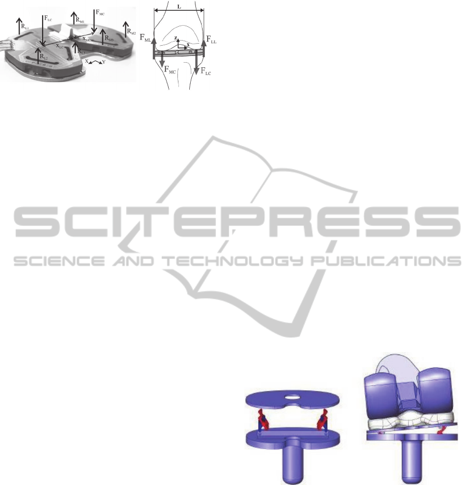
Figure 2: The forces measured by the tibial force-sensing
device (Crottet et al., 2005).
This flexibility of usage allowed a better bone
cuts planning, a more accurate components
positioning and gave the possibility to carry out fine-
tuning balance corrections with a high level of
precision. However, a major limitation stood in the
way ligaments were modelled for the computations:
they were reproduced by means of springs, a clearly
too strong approximation (Marmignon, 2004).
1.2 Description of the First proposed
Model
In the literature we can find many other
instrumented implants that actually own diagnostic
capabilities, but could only exploit them in the
intraoperative period. This means that they are used
as measurement tools before the pose of the actual
knee prosthesis, which will be installed once the
optimal conditions are set up. On the other hand,
what we want to develop is an adjustable prosthetic
component to be employed not only during TKA
surgery, but also postoperatively. Given that
tibiofemoral alignment conditions can be perfectly
obtained thanks to well-developed Computer-
Assisted Total Knee Arthroplasty (CATKA)
techniques, we focus on the problem of monitoring
and assessing collateral ligament tension values.
We refer to the smart knee implant proposed by
Almouahed et al. (2010). An instrumented tibial
component, part of a total knee prosthesis, was
equipped with four piezoelectric elements, intended
to be used as both force sensors and energy
harvesters. The total thickness of the tibial
component was 4.5 mm, in line with usual
dimensions. A first-version prototype of the entire
implant was developed and studied in laboratory by
direct wiring.
Collateral ligament balance conditions were
evaluated by adopting a Center of Pressure (CoP)-
based approach. Collected data were supposed to be
transmitted to the outside of the prosthesis thanks to
a wireless telemetry system (Lahuec et al., 2010). A
microprocessor and an antenna could be hosted in
the hollow stem of the tibial component. A very
strong point of this transmission system was its
characterisation as being totally self-powered. Its
power-supply was completely ensured by the
electric energy harvested by the four piezoelectric
elements during gait cycle motions.
System feasibility was confirmed by theoretical
studies (Almouahed et al., 2011) and a partner
laboratory is currently working on the power issue in
order to obtain definitive results.
This instrumented knee implant is the first one
able to postoperatively monitor and assess collateral
ligament balance, during an active range of motion
and without the need to be powered by an external
source of energy. Upon achievement of such
diagnostic capabilities, our next objective was to
actuate this knee implant, in order to have an active
prosthesis able to compensate for the detected
imbalance by autonomously correcting the position
of its components.
In a recent study (Almouahed et al., 2012) we
further developed this knee implant. We proposed to
instrument it with two embedded microactuators. In
this new design, the tibial component consisted of a
fixed baseplate and a mobile tray, the latter
connected to the former by means of two scissor lift
mechanisms (a Medial and a Lateral one). The goal
was to be able to move upwards and downwards the
upper mobile plate (Figure 3).
Figure 3: Location and example of use of the two scissor
lift mechanisms embedded in the fixed tibial baseplate
(Almouahed et al., 2012).
In this way, the relative position between the
polyethylene insert (properly fixed on the upper
surface of the mobile plate) and the fixed tibial part
could be adjusted in order to meet correct balance
conditions, both intraoperatively and
postoperatively. Each scissor mechanism was
supposed to be driven by a sliding pin, controlled by
a miniature linear actuator positioned in the fixed
tibial part.
TowardsaDynamicTibialComponentforPostoperativeFine-tuningAdjustmentofKneeLigamentImbalance
97
A detailed 3D CAD model of the whole implant
was realised and studied. Simulations led to the
estimation of its minimum lifespan and of the points
where peak Von Mises stresses occurred. More
practical issues, like the choice of a suitable
micromotor and its power supply, were not
considered. In this current work, we approach such
problems and propose a new design for the
adjustable autoadaptive knee implant.
2 POSSIBLE APPROACHES
After consultation with orthopedic surgeons, we
know that to restore a proper collateral ligament
tension we need to be able to lift up one side of the
mobile tibial plate, according to the detected loose
ligament (medial or lateral). We should be able to
compensate for up to 3 mm vertical distance, in
order not to affect the tibiofemoral alignment of the
prosthesis with respect to the lower limb mechanical
axis. The level of accuracy is clearly submillimetric.
The peak tibiofemoral force acting on the tibial
component during gait cycle is 2600 N (ISO 14243-
3, 2004). Consequently, the actuation system that we
are designing must be robust and resistant to strong
cyclic efforts.
The lift up of the tibial plate is carried out with
the patient in supine position. In such a condition,
the only tibiofemoral forces acting inside the knee
joint are due to collateral ligament tensions, which
result in a total compressive force of 150 N on each
side of the tibial plate (Marmignon, 2004). This is
the reference value that we need to consider while
looking for a good design.
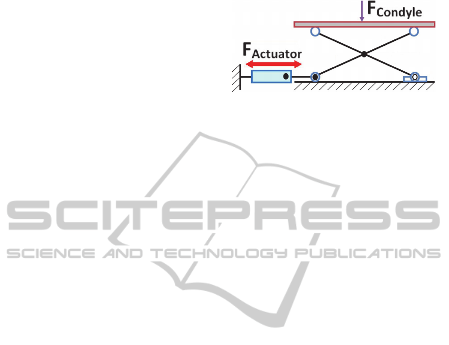
A first consideration about the validity of the
proposed scissor lift mechanism can already be
made. Considering the entity of tibiofemoral efforts
and the small dimensions of the scissor structure, in
fact, a too high reaction force would be transmitted
to the micromotor shaft (Figure 4).
Simulations showed that, for a 3 mm lift up, the
peak tibiofemoral force of 2600 N acting on the
tibial baseplate would transmit to the actuator a
force higher than 4500 N. It does not exist any
micromotor tiny enough so as to fit the available
volume and, at the same time, able to oppose such
an important passive force.
A normal linear micromotor of dimensions
3x3x6 mm typically offers a stall force of 0.3 N.
These values are clearly too far from normal knee
cyclic efforts entity. The locking system is a key
issue for the implant durability and the scissor lift
mechanism is not a reliable solution.
Figure 4: The tibiofemoral efforts are transmitted to the
micromotor shaft via the scissor lift mechanism
(Almouahed et al., 2012).
The available volume to host the actuation
system is very small. We mainly have two
exploitable volume regions: the hollow cylindrical
tibial stem (17 mm diameter and 40 mm height) and
the fixed tibial baseplate (75x50 mm, 4.5 mm thick).
In addition to this, we can obtain further space by
removing a reasonably small bone quantity from the
resected tibia surface.
Everything must be carefully miniaturised. The
research of suitable components itself is really
complex and it gets strongly restricted by the
biocompatibility issue. We immediately discard any
invasive component, as well as any wireless power
transmission technique which may cause biological
damages.
We focused on three approaches to realise the
desired actuation: (1) to embed a micromotor within
the tibial baseplate, in order to move a miniaturised
mechanical structure, (2) to exploit the presence of
metallic/ferromagnetic components, properly
disposed inside the tibial implant, to be moved
without contact by exploiting the action of an
external magnetic field and (3) to use an external
tool to access to the prosthesis from outside, through
two small incisions, so as to adjust an internal
mechanism.
In the following, we will detail our research
activity. We will consider each approach and
highlight their advantages and drawbacks. After this
analysis, we will motivate the final choice of the
adopted approach.
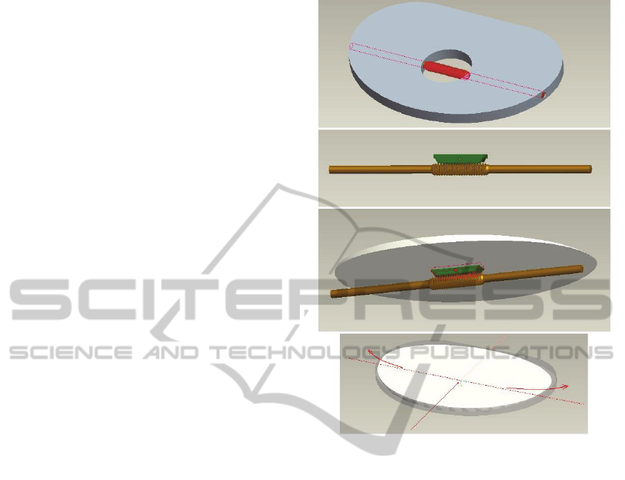
2.1 Micromotor-based Approach
This is the most intuitive choice. Regardless of the
chosen design, a very strong point of microactuators
consists in the high accuracy level that they ensure
in mechatronic applications. The control of
electronic components can be very efficiently
achieved and provides reliable data.
The scissor lift mechanism was set aside, but a
priori we still have a wide variety of possible
BIODEVICES2013-InternationalConferenceonBiomedicalElectronicsandDevices
98
mechanical structures that can be embedded in the
prosthesis. In these terms, while component sizing is
not a big deal, a good trade-off must be found
between their dimension and their power. More
specifically, we need to find a micromotor which is
small enough and, at the same time, sufficiently
powerful. This is usually quite complicated, because
small dimensions inevitably give reduced
performances.
As previously explained, another problem is
represented by the locking issue. The micromotor
must be able to realise the actuation and keep the
new adjusted position with high durability. This
must be ensured by proper design solutions.
A further drawback of this approach is that the
micromotor needs to be powered and controlled
wirelessly. This is not easy to achieve, since even
miniaturised motors are not low-power consumption
devices (in general, 2-3 V power supply is needed).
However, all the necessary components for motor
control and data transmission (microprocessors,
integrated circuit and telemetry system) must be
positioned inside the prosthesis. As a consequence,
they all need to be miniaturised and assembled in the
optimal way so as to fit the very small available
volume.
2.2 Magnetic Field Interaction-based
Approach
This approach is based on the action of an external
magnetic field properly generated around the knee.
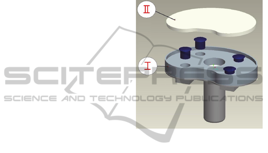
The idea is to embed four magnetic screws within
the fixed tibial baseplate and control their screwing
without any contact, by exploiting magnetic
interaction. In their starting configuration, the
screws are completely embedded in the tibial tray
(Figure 5), located in their housings that are
perpendicular to the baseplate surface. Screw heads
are in contact with the upper mobile plate and, when
unscrewed, they push it up and realize its lateral lift
on the desired side. At least two screws for each
side, medial and lateral, are needed in order to
ensure good stability conditions.
The use of magnetic fields in biomedical
applications is very common. From the
biocompatibility point of view, then, a priori this
approach should not be problematic. Magnetic fields
can be generated with specific tools, often equipped
with coils that are generally fixed to their lower limb
only during the medical visit. Such devices are not
invasive and usually fit to the patient's morphology.
A strong point of magnetic screws is that they
actually are passive components that offer a very
long lifespan. They do not require any power supply,
not even during the actuation process. The tensile
strength and resistance that they offer depend on
their diameter (between 0.5 and 1.5 mm) and pitch,
two values to be both optimised (preferably
according to ISO standards) in order to optimise
wear resistance properties.
Figure 5: The screws embedded within the intermediate
fixed tibial tray (I), in order to push up or down the upper
mobile plate (II).
Nowadays the control of magnetic fields is
achieved with very high accuracy and magnetic
interaction is actually exploited in many high-
precision positioning devices. In our case, we could
find some difficulties in localizing the action of the
external field on one single screw, while avoiding
any interaction with the other three. Operating
conditions get severely complicated by the reduced
spaces we face with. In order to have a good control
of the screws through the biological tissues and the
prosthetic parts, the magnetic field we need has to be
very precise and strong. At the same time, the
biocompatibility constraint imposes not to damage
biological tissues. Then, the magnetic action should
not be too powerful. In these terms, a good
compromise has to be found.
Another biocompatibility aspect is represented
by the presence of ferromagnetic elements inside the
human body. The material chosen for composing the
magnetic screws must not be dangerous for the
patient and should not limit their daily life activities.
A more delicate issue is the mobility of magnetic
screws and the resistance they oppose to motion. In
TowardsaDynamicTibialComponentforPostoperativeFine-tuningAdjustmentofKneeLigamentImbalance
99
other words, we want to adjust their screwing
without making a too high effort; on the other hand,
once in the new position, we want them to be solid
and rigidly fixed, so as to provide a good resistance.
2.3 External Tool-based Approach
This is an alternative approach, based on an external
tool employed to access to the prosthesis and adjust
its shape. We start from the consideration that small
skin incisions under 5 mm length leave no scar after
recovery. The tibial baseplate of the installed TKA
prosthesis can be accessed through two small
incisions, a medial and a lateral one. The idea is to
use a custom-designed tool, that we can define as a
“double screwdriver”, in order to adjust the position
of the upper mobile tibial plate.
In this particular design, the fixed tibial tray
embeds a worm screw. Its thread is in contact with a
corresponding worm gear part located on the lower
surface of the mobile plate (Figure 6). The two
threads considered together form a worm drive gear
arrangement. Thanks to their relative position, the
rotation of the screw produces the one-side shift of
the mobile tibial plate. This movement modifies the
inclination of the polyethylene insert only along the
Medio-Lateral direction, without modifying the
prosthesis aligmnent with respect to the lower limb
mechanical axis. The overall tibial component
thickness is 7 mm and the mobile plate can be lifted
up to 3 mm maximum.
The most interesting aspect of this approach is its
extremely low invasiveness: general anaesthesia
procedure is not required and no scar will remain on
the patient's skin. Consequently, the hospitalisation
period can be greatly reduced and this represents a
very interesting advantage to the patient.
The worm drive structure that is embedded
within the tibial tray is actually a passive structure. It
does not need any power supply and it ensures a
very long lifespan. Only when the external tool is
employed, the positioning mechanism responds to its
solicitations and realizes the prosthesis actuation.
Another very strong point of the worm drive
structure is its natural mechanical irreversibility. The
worm screw rotation causes the worm gear motion
and not viceversa. Once the desired inclination is
set, tibiofemoral forces keep on pushing on the
upper plate surface through the polyethylene insert.
This action produces the rotation of the worm gear
part which is rigidly fixed onto the lower surface of
the mobile plate. Thanks to the system's
irreversibility, this rotation does not produce any
movement and the new position is solidly kept.
Figure 6: The worm drive gear arrangement is completely
embedded in the tibial component and controls the medio-
lateral translation of the upper mobile tibial plate.
A further advantage of this approach is the fact
that the external tool can be custom-designed. Thus,
both its performances and control can be very
accurately defined.
Unfortunately, the risk of infection is a really
serious drawback. Even if nowadays sterilisation
procedures are very reliable, especially in hospital
environments, the introduction of any external body
inside the knee articulation after TKA surgery is still
not recommended. Any single bacterium that, by
chance, enters in contact with the prosthesis-bone
interface might be able to initiate an infection
process. In the worst-case scenario, after just one
month even the prosthetic detachment might take
place.
Another problem of the proposed design is the
fact that the medio-lateral translation of the mobile
tibial plate modifies the tension of both the collateral
ligaments at the same time. The tray slides laterally
and gets lifted up on the side corresponding to the
loose ligament. At the same time, the lift down of
the plate on the other side inevitably releases the
other ligament. In this sense, it gets more difficult to
BIODEVICES2013-InternationalConferenceonBiomedicalElectronicsandDevices
100

define a proper correcting action since the tension
values of both the collateral ligaments must be
continuously monitored.
3 SELECTED APPROACH AND
PROPOSED MODEL
After the analysis of the advantages and drawbacks
of each possibility, the micromotor approach was
selected as the most reliable choice in terms of
accuracy and performances. For our application,
precision is a key issue and microactuators can be
very reliably controlled. The drawbacks we
considered about them (the dimensions/power
compromise, the locking system and wireless
alimentation and control) all represent technological
limitations that can be overcome by proper design
solutions.
The only micromotor technology that properly
satisfies all the constraints of our project is that of
piezoelectric motors. They can produce very strong
actuation forces even if their dimensions are
incredibly small. Moreover, besides a very long
lifespan, they offer a nanometer positioning
accuracy. A manufacturer we are currently in
contact with produces such kind of microactuators
with a very interesting feature: both the power
supply and the motor control are carried out by
radiofrequency. RFID transmission ensures low
power consumption (less than 0.5 V obtained by
electrical impulses at a given frequency) in
conditions of perfect biocompatibility and very fast
response times (less than 1 ms).
In this work we can introduce the original
actuation design we are developing. A more detailed
description will be object of a future publication, on
which we are already working. Basically, the most
relevant differences between this design and the
previous ones stand in: (1) the direction in which
actuation is realised and, consequently, (2) the type
of micromotor we want to employ.
Tibiofemoral efforts act perpendicularly with
respect to the mobile tibial plate that we want to lift
up. As shown for the scissor mechanism model, a
linear micromotor acting on the tibial baseplate
plane would be greatly involved in the locking
procedure, not being able to ensure system solidity.
In our new design, the mobile plate lift up is
realised thanks to the displacement of some specific
components inside the tibial baseplate. This
displacement is driven by a screw-nut mechanism
where the screw can only rotate and the nut
translates. The screw head is rigidly connected to the
shaft of a rotary piezoelectric micromotor, which
can be wirelessly controlled by the clinician. Thus,
the overall system positioning can be achieved with
high precision.
The most interesting aspect of such design is that
the micromotor is not involved in the locking
procedure. The screw-nut system is properly
dimensioned so as to be irreversible. This property is
exploited to solidly keep the mobile tibial plate in its
desired lifted up position.
Besides the realisation of a detailed 3D CAD
model of the proposed tibial component, a
theoretical mechanical study of the system has been
carried out to evaluate the force distribution among
the different components. Initial results showed that
a 0.6 Nm torque is able to realise the actuation and
laterally lift the mobile tibial plate up to 3.3 mm.
Moreover, solidity and resistance are ensured by the
screw-nut thread, which offers great tensile strength
performances. These results are quite encouraging
and we are currently working on their improvement
and optimisation.
4 CONCLUSIONS AND
PERSPECTIVES
In this paper we discussed an instrumented tibial
component to be used both intraoperatively and
postoperatively. The two objectives of our work
consisted in being able to check collateral ligament
tension conditions and correcting potential
imbalances.
The first point was achieved by employing the
instrumented tibial implant that had been previously
proposed by our team. In this model, four
piezoelectric elements were embedded into the tibial
tray and their use successfully provided diagnostic
data about ligament tension values.
In order to reach the second goal, the operation
to be performed in order to restore proper ligament
tension values consisted in adjusting the position of
the tibial tray. The implant was initially supposed to
be actuated by two scissor lift mechanisms. This
design was not able to ensure proper blocking
conditions and could not meet all the constraints of
the project. Thus, the scissor lift mechanism was
rejected in favour of another design which could be
able to better face with normal knee operating
conditions.
We considered three different approaches to
realize the prosthesis actuation: the first one with a
TowardsaDynamicTibialComponentforPostoperativeFine-tuningAdjustmentofKneeLigamentImbalance
101

micromotor, the second one with a magnetic field
and the last one with an external tool. Our research
work consisted in evaluating the advantages and
drawbacks of each case. This led us to select the
micromotor approach as the most reliable one.
Different design solutions have been analysed
and discussed. We are currently developing an
original design of the actuated tibial implant, based
on the use of two rotary piezoelectric motors. This
model has been theoretically studied and simulations
on a detailed 3D CAD model proved its feasibility.
The 3D model optimisation stage will be followed
by the realization of a prototype, which will be
tested with a knee simulator. Results will be
presented in a future work.
REFERENCES
Almouahed, S., 2011. Etude, mise en oeuvre et évaluation
de prothèse autonome et prédictive du genou. Ph.D.
Télécom Bretagne - LaTIM INSERM U1101, Brest.
Almouahed, S., Gouriou, M., Hamitouche, C., Stindel, E.,
Roux, C., 2010. Design and evaluation of
Instrumented Smart Knee Implant. In IEEE
Transactions on Biomedical Engineering, vol. 58, n°
4, pp. 971–982.
Almouahed, S., Gouriou, M., Hamitouche, C., Stindel, E.,
Roux, C., 2011. The use of piezoceramics as electrical
energy harvesters within instrumented knee implant
during walking. In IEEE/ASME Transactions on
Mechatronics, Focused Section on Sensing
Technologies for Biomechatronics, vol. 16, pp. 799-
807.
Almouahed, S., Hamitouche, C., Stindel, E., Roux, C.,
2012. Finite Element Lifetime Prediction of a
Miniature Adjustable Orthopedic Device. In 34th
Annual International Conference of the IEEE
Engineering in Medicine and Biology Society
"Engineering Innovation in Global Health" -
EMBC'12.
Crottet, D., Maeder, T., Fritschy, D., Bleuler, H., Nolte, L.
P., Pappas, I. P., 2005. Development of a force
amplitude- and location-sensing device designed to
improve the ligament balancing procedure in TKA. In
IEEE Transactions on Biomedical Engineering, vol.
52, pp. 1609-1611.
International Organisation for Standardization, 2004. ISO
14243-3 Implants for surgery – Wear of total knee-
joint prostheses – Part 3: Loading and displacement
parameters for wear-testing machines with load
control and corresponding environmental conditions
for test.
Lahuec, C., Almouahed, S., Arzel, M., Hamitouche, C.,
Jézéquel, M., Stindel, E., Roux, C., 2010. A self-
powered telemetry system to estimate the
postoperative instability of a knee implant. In IEEE
Transactions on Biomedical Engineering, vol. 58, n°3,
pp. 822–825.
Marmignon, C., 2004. Modèle et instruments robotisés
pour l'étude de la biomécanique per-opératoire de
l'équilibre ligamentaire du genou. Ph.D. Université
Joseph Fourier, Grenoble.
Marmignon, C., Leimnei, A., Cinquin, P., 2004. Robotized
distraction device for knee replacement surgery. In
Proc. CARS, pp. 638-643.
Marmignon, C., Leimnei, A., Lavallée, S., Cinquin, P.,
2005. Automated hydraulic tensor for Total Knee
Arthroplasty. In Int J Med Robot, vol. 1, n
o
4, pp. 51-
57.
Scuderi, G. R. and Tria, A. J., 2006. Knee Arthroplasty
Handbook: Techniques in Total Knee and Revision
Arthroplasty, Springer. New York.
Vail, T. P., Lang, E., 2006. Surgical techniques and
instrumentation in Total Knee Arthroplasty. In: W. N.
Scott, Surgery of the Knee, Churchill Livingstone, pp.
1493-1498. New York.
Winemaker, M. J., 2002. Perfect balance in total knee
arthroplasty: the elusive compromise. In Journal of
Arthroplasty, vol. 17, n
o
1, pp. 2-10.
BIODEVICES2013-InternationalConferenceonBiomedicalElectronicsandDevices
102
