Computational Study of the Electrostatic Coupling of
Membrane-spanning α-Helices Controlled by Dielectric Media
Tarunendu Mapder and Lipika Adhya
Department of Engineering Physics, B. P. Poddar Institute of Management and Technology,
137, V.I.P. Road, Calcutta-700052, India
Keyword: Voltage Gated Ion Channel.
Abstract: Voltage-gated potassium ion-channels (Kv) play a key role in neurons. The ion-channel is a tetramer each
having two domains: voltage senor-domain (VSD) and pore-domain (PD), with four (S1-S4) and two (S5-
S6) α-helices respectively, which behave like macrodipoles. The VSD appears capable of adopting different
orientations relative to the pore-domain of Kv channels in response to the variable (-70V to +30V)
transmembrane-voltage controlling the passage-way of the K+ ions across the membrane. There is an
immense progress in the study of voltage-gated channel; however the molecular mechanism underlying
voltage sensing is still a matter of debate. Here, we have used a novel theoretical approach using
electrostatic theory to identify the possible stable conformation of the voltage gated potassium ion-channel
of Aeropyrum pernix (KvAP) at zero transmembrane-voltage by computing the minimum potential energy
of the system embedded in hybrid dielectric environment. We have set up an algorithm to generate data,
which is presented graphically and then analyzed to study the configuration of the biological system of
KvAP. It is observed that in ion-channel protein two adjacent α-helices behaving like a macrodipole
conform to antiparallel arrangement and the involvement of the charged residues with the multidielectric
environment gives the ion-channel protein different conformations.
1 INTRODUCTION
The key process underlying the electrical activity of
excitable tissue (neuron) is the voltage-dependent
opening and closing of tetrameric Na
+
, Ca
2+
, and K
+
channels. This gating action is mediated by a voltage
sensor whose movement is somehow coupled to an
intracellular activation gate contained within the
channel’s pore domain (Yellen, 1998). The K
+
channel is composed of four identical or
homologous subunits, each containing six
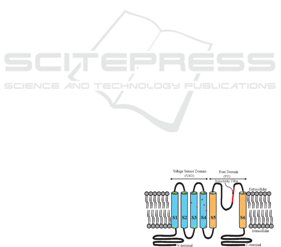
transmembrane α-helices: S1–S6 (Figure 1). α-
helices S1–S4 form the voltage-sensing domain
(VSD), and α-helices S5 and S6 connected by the P
loop, which is involved in ion selectivity, comprise
the pore-forming α-helices domain (PD). The most
mobile S4 has four gating-charge-carrying arginines
(R1–R4) spaced at intervals of three amino acid
residues, which are highly conserved and are
thought to play a key role in coupling changes in
membrane voltage to opening and closing of the
pore.
The structure and the function of different
voltage-gated potassium ion channels have been
reviewed (Borjesson and Elinder, 2008).
Figure 1: Schematic diagram of KvAP ion channel
monomer at membrane-spanning orientation. The helices
ion of VSD (S1, S2, S3, S4) (blue) and PD (S5, S6)
orange. The (+) and (-) are position of charges; charged
amino acids (reds), N-terminal charge (+) and C-terminal
charges (-). (The figure is generated by 3D Max).
S4 always stay together, while the other helices
of the voltage sensor domain (VSD) present
different spatial In the structures of KvAP obtained
111
Mapder T. and Adhya L..
Computational Study of the Electrostatic Coupling of Membrane-spanning α-Helices Controlled by Dielectric Media.
DOI: 10.5220/0004193601110115
In Proceedings of the International Conference on Bioinformatics Models, Methods and Algorithms (BIOINFORMATICS-2013), pages 111-115
ISBN: 978-989-8565-35-8
Copyright
c
2013 SCITEPRESS (Science and Technology Publications, Lda.)
by different methods (Jiang et al., 2003a); (Lee et
al., 2005); (Butterwick and MacKinnon, 2010) the
S3b and orientations. Each of these helices forms a
macrodipole and can potentially contribute to the
electrostatic field.
Here, we have made use of an application of
information technologies and computational
systems to understand the configuration of a pair of
helices (S3b-S4) of the voltage gated potassium ion
channel of Aeropyrum pernix (KvAP) at zero
transmembrane voltage.
2 THEORY
2.1 Model of a Pair of Antiparallel
α-Helix
The voltage-gated ion channel protein (KvAP)
which is a transmembrane helix-turn-helix protein in
lipid and ionic environment is modeled as an
aggregation of macrodipoles in a hybrid or complex
dielectric environment. A α-helix possesses a dipole
moment by virtue of the alignment of its peptide
bonds having half-positive and negative charges at
their ends respectively. For this fractional charge
separation, a single peptide unit behaves like a
microdipole (Wada, 1976). When these microdipoles
align along the axis of the α-helix, making hydrogen
bonds with the neighboring peptide units, it behaves
like a macrodipole (Hol 1978) with positive C-
terminal and negative N-terminal on either end.
The VSD has four such antiparallel α-helix
macrodipoles (S1, S2, S3a-S3b, S4). The S3b-S4
helix-pair “paddle” of the voltage sensor domain
(PDB: 1ORQ) in the x-ray crystallography structure
of KvAP is selected for the simulation of the helix-
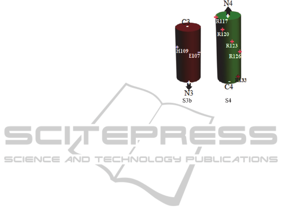
pair. The S3b contains a positively charged Histidine
(H109) and a negatively charged Glutamic acid
(E107) (Figure 2). On the other hand S4 contains
five positively charged Arginines (R117, R120,
R123, R126 and R133). Except Histidine which is
half, all the residues have unit charge. Apart from
the charged residues, the contributions of the
terminal charges of the helix dipoles are half unit at
two positive N-terminals (N3, N4) and two negative
C-terminals (C3, C4). The length of the S3b and S4
helices are 19.5Å and 24.0Å respectively. The
Histidine (H109) is 3.0Å above and 200º apart
(clockwise) from E107. On S4 the first charged
residue R117 is at the positive N-terminal (N4),
while the others are placed 60º, 120º, 180º, and 200º
clockwise away from and 4.5Å, 9.0Å, 13.5Å, and
24.0Å below R117 respectively.
Figure 2: The S3b and S4 helix pair with the charges. C3,
N3, N4 and C4 are the terminal dipole charges and the
arrows specify the direction of the dipole moments of the
two helices. R17, R120, R123, R126 and R133 are the
positively charged arginines on S4 and on S3b, H109 and
E107 are positively charged Histidine and negatively
charged glutamic acid respectively. (The figure is
generated by 3D Max).
The interaction potential energy of the system of
charges on S3b-S4 macrodipoles is calculated to
study the mutual configuration between S3b and S4
helices. Three parameters of motion of S4 are
considered. 1) The angle of rotation (θ°) about its
own axis; 2) the relative translational (x Ǻ) with
respect to S3b; 3) the oscillation (°) in the plane
parallel to S3b. At θ=0.0°, x=0.0Å and =0.0°, R117
of S4 helix faces E107 of S3b, which is perfectly
parallel to S4. With the variation of x, S4 slides
along S3b. At different combinations of theta and x
values different residues come in front of E107.
2.2 Electrostatic Principle Holding the
Macrodipoles Together
On the basis of the principle of electrostatic theory,
the antiparallel arrangement is best understood by
dipolar interactions in which the mutual potential
energy (PE) of two interacting adjacent
macrodipoles depends upon their dipole moment ()
and varies with their relative angular separation ()
(Mahajan, 1988). The two dipoles tend to orient so
as to achieve the minimum PE of the system. Lower
the PE, more stable is the conformation. When they
are parallel (=0°) the PE is maximum; when
perpendicular (=90°) PE is zero, and when
antiparallel (=180°), the PE reaches a minimum
value (Mapder and Adhya, 2012).
When the dipoles are very close to each other
(i.e. the distance between the two dipoles is smaller
BIOINFORMATICS2013-InternationalConferenceonBioinformaticsModels,MethodsandAlgorithms
112
than their length) the interaction of the pole charges
plays a dominant role. Due to electrostatic attraction,
the two opposite poles of the antiparallel dipoles
possess a negative Coulombic potential energy
(PE
coulomb
) (Eqn 1a), while a positive potential
energy is possessed by the two similar poles of
parallel dipoles.
Coulomb Energy;
PE
coulomb =
π
∑
,
,
(1a)
When the charges are near the boundary of two
different dielectric media, opposite charges are
induced on the dielectric interface. These induced
charges interact with the original charges by the
method of image charges (Jackson, 1975),
contributing (a) self energy (PE
self
) (Eqn 1b) and (b)
shielding energy (PE
shield
) (Eqn.1c). PE
self
is due to
the dielectric screening of the charge in its own
medium. When there is an interaction between two
charges in two different media, then both charges are
shielded by their respective media creating a
shielding effect to the columbic interaction energy
(PE
shield
).
Self Energy;
PE
self
=
πϵ
∑
,
;
(1b)
Shielding Energy;
PE
shield
=
πϵ
∑
,
;
(1c)
where
,
are the charged residues in dielectric
medium of dielectric constant,
,
respectively and
,
are the distances of the respective charged
residues from the dielectric interface and
is the
distance between two charges. The ½ factor in the
coulomb energy and the shield energy is to eliminate
the duplicity of the summation on i
th
and the j
th
particles.
From the superposition principle, the total
electrostatic potential energy PE
total
of the system of
charges present on S3b and S4 helices will have
three prominent contributions.
PE
total
= PE
coulomb
+ PE
self
+ PE
shield.
3 RESULTS AND DISCUSSION
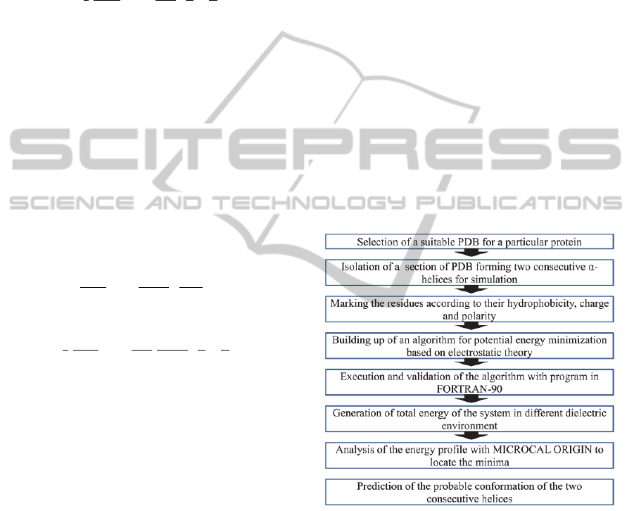
The computation study of the voltage gated ion
channel of KvAP follows the flow chart (Figure 3)
to predict the probable conformation of the S3b-S4
pair at zero transmembrane potential. From the
Protein Data Bank (PDB 1ORQ) the sequence of the
voltage gated potassium ion channel of KvAP is
selected. A section of the VSD of 34 residues is
considered forming helix-turn-helix S3b-S4 pair.
The S4 α-helix is presumed to be more mobile than
S3b. With all probability the S4 helix can have all
possible motions; (1) rotational motion (º) about its
helix axis, (2) translational motion (x Å) along its
axis and (c) oscillatory motion (βº) in the plane
parallel to S3b. The interaction potential energy
between the charged residues of S3b (+N3, -E107,
+H109, -C3) and S4 (+N4, +R117, +R120, +R123,
+R126, +R133, -C4) α-helices is calculated by
rotating, translating and oscillating S4 with respect
to the negative charged residue E107 of S3b. The
interaction potential energy varies with the motion
of S4 as all the charges between S3b and S4 move
closer to or farther away from each other. The
opposite charges produce negative or attractive
interaction energy while the similar charges produce
positive or repulsive energy. The total potential
energy is the summation of all the interactions.
Figure 3: The flow chart showing the pathway to predict
the probable conformation of protein.
The S3b-S4 helix pair is a part of the VSD which
is embedded in protein. However, helix S4 is
particularly being too mobile gets partially exposed
to lipid. The variation of the exposure depends on
the inclination of S4 into the hydrophobic lipid
(Figure 4). Therefore the charged residues get
exposed to either protein or lipid. Depending upon
the exposure to different dielectric membrane the
total energy varies even though the inclination of the
S4 is fixed. At different angular rotation () of S4
ComputationalStudyoftheElectrostaticCouplingofMembrane-spanningAlpha-HelicesControlledbyDielectricMedia
113
different arginines is at the lipid-protein interface
e.g. residues R1, R2, R3 and R4 are at 120° and
240°, 195° and 285°, 270° and 330° and 15° and
345° respectively (Figure 4). The potential energy
(PE) of the S3b-S4 system of charges is generated
by the algorithm run by the program in Fortran-90
keeping S3b stationary and S4 in motion by rotation,
translation and oscillation. S4 helices laden with
positively charged residues have a strong attractive
interaction with E107 of S3b comparable to the
interaction with other charges (Mapder, 2012).
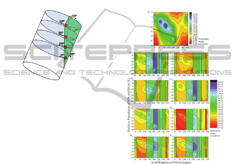
Figure 4: Schematic diagram of S4 helix partially exposed
to lipid (green). R1, R2, R3 and R4 (different levels from
the top) at the lipid-protein interface at an angular rotation
(labeled) of S4 about its axis; (red dot-in front; yellow dot-
at the back). (The figure is generated by 3D Max).
The contour (Figure 5) shows the gradation of
PE of S3b-S4 α-helix pair at different configuration.
The interaction is attractive and comparatively
stronger when the positive arginines residues ( R1,
R2, R3, R4, R5) are at the vicinity of the negative
E107 of S3b, showing five low energy contour-line
at different (°, xÅ) coordinates e.g. (0°,0.0Å), (60°,
4.5Å), (120°, 9.0Å), (180°, 13.5Å) and (200°,
24.0Å) respectively. The S3b-S4 pair in different
dielectric medium has different conformations.
When the helix pair is in uniform dielectric (e.g.
protein ε=10.0) environment (Figure 5a) the arginine
(R123) of S4 is at the vicinity of the negative E107
of S3b, while when this pair is in a hybrid dielectric
environment (lipid ε
l
=2.0, protein ε
p
=10.0 and water
ε
w
=80.0) (Figure 5b) the S4 takes a new
conformation, with R126 of S4 facing the E107 of
S3b.
There are various evidences (Borjesson, 2008)
showing that the arginine of S4 has a vital role in the
gating process. Our theory explains that these
charged residues are also responsible for the mutual
conformation of S3b-S4 pair at zero potential. By
virtual mutagenesis of individual arginine of S4 the
energy range and its gradation changed. On mutating
each charged residues, each contour plot (Figures
5c-5f) shows only four such low energy contours
indicating that there is no energy contribution of the
missing charged residue at their respective positions.
In absence of R117 the energy of S3b-S4 has energy
minimum at =285° i.e. none of the charges are
facing S3b, while in absence of R120 the energy
minimum is at 175° i.e. R126 is at the vicinity of the
S3b. Virtual mutagenesis explains that each residue
has a role in conforming S3b-S4 together at zero
potential.
Figure 5: Electrostatic potential energy contour of the
system of charges of S3b-S4 pair with axial rotation (°)
and translation (xÅ) of S4; in (a) uniform medium (b)
hybrid medium. With virtual mutagenesis of (c) R1, (d)
R2, (e) R3, (f) R4, (g) R5 (h) N4, (i) C4. The vertical lines
indicate the lipid-protein interface faced by the charged
residues. (The figure is generated by Microcal Origin).
The figures (5g and 5h) shows the change in the
range of the total energy when the dipolar terminal
charges are neutralized. Therefore, these end
terminal charges even though they are weaker; they
do have a contribution in the stabilization of the
S3b-S4 conformation.
When S3b-S4 pair is in hybrid dielectric medium
environment, the vertical contour explains the
position of the respective charges near the lipid-
BIOINFORMATICS2013-InternationalConferenceonBioinformaticsModels,MethodsandAlgorithms
114

protein interface. Comparing Figure 3 and Figure
5(b-i), it is quite apparent that whenever the
environment of any one of the charge changes the
total energy also changes. If the change in the
dielectric constant is from a lower to a higher value
(e.g. from lipid to protein) the potential energy of the
system, changes from a lower to a higher range and
vice versa. It is an inherent property of any system is
to minimize its potential energy to attain stability.
This explains that the interaction of the charge with
the hydrophobic lipid membrane is favored.
4 CONCLUSIONS
The helix-turn-helix S3b-S4 pair in voltage sensor
domain of KvAP tries to accommodate, in a
membrane-spanning multi-dielectric environment at
zero potential, in such a fashion that the electrostatic
coupling of the inter-helix charges can attain a
minimum potential energy electromechanical
equilibrium. The stable conformations of the helix
pair is dependent not only on the inter helix charge
interaction but also on the hybrid dielectric
environment, which supports the conformation. For
proper understanding of the mechanism of voltage
sensor, it is important to know the zero potential
conformation of the S3b-S4 couple in the
appropriate hybrid dielectric environment. This can
give an insight to the researchers working in this
field to trace the movement of the VSD under the
influence of the variable transmembrane voltage.
Our program can be applied to all types of protein
which are in the form of amphipathic helices.
ACKNOWLEDGEMENTS
This work is sponsored by SR/SO/BB/0080/2009 of
the Department of Science and Technology, Govt. of
India.
REFERENCES
Borjesson, S. I. and F. Elinder. 2008. Structure, function,
and modification of the voltage sensor in voltage-
gated ion channels. Cell Biochem Biophys 52:149-174.
Butterwick J. A. and MacKinnon R., 2010 Solution
structure and phospholipid interactions of the isolated
voltage-sensor domain from KvAP. J Mol Biol 403
591-606.
Hol, W. G., P. T. van Duijnen, and H. J. Berendsen, 1978.
The alpha-helix dipole and the properties of proteins.
Nature. 273: 443-6.
Jackson, J. D., 1975. Classical Electrodynamics; Wiley,
New York.
Jiang Y., Lee A., Chen J, Ruta V., Cadene M., Chait B. T.
and MacKinnon R., 2003a. X-ray structure of a
voltage-dependent K+ channel. Nature 423 33-41.
Lee S. Y., Lee A., Chen J. and MacKinnon R., 2005
Structure of the KvAP voltage-dependent K+ channel
and its dependence on the lipid membrane. Proc Natl
Acad Sci U S A 102 15441-6.
Mahajan, A. S., and Rangawala, A. A., 1988. Electricity
and Magnetism, 1
st
ed. Tata McGraw-Hill Publishing
Company Limited, New Delhi.
Mapder, T., Adhya S. and Adhya L., 2012. Electrostatic
interaction between dipoles and side chains in the
voltage sensor domain of K+ channel. J. Nat. Sc. Biol.
& Med. (in press).
Wada, A., 1976. The alpha-helix as an electric macro-
dipole. Adv Biophys. 1-63.
Yellen, G., 1998. Premonitions of ion channel gating. Nat
Struct Biol 5:421.
ComputationalStudyoftheElectrostaticCouplingofMembrane-spanningAlpha-HelicesControlledbyDielectricMedia
115
