
Secure UHF Tags with Strong Cryptography
Development of ISO/IEC 18000-63 Compatible Secure RFID Tags
and Presentation of First Results
Walter Hinz, Klaus Finkenzeller and Martin Seysen
Giesecke & Devrient GmbH, Prinzregentenstrasse 159, 81677, Munich, Germany
Keywords: UHF Tag, Public Key Cryptosystem, Rabin, Montgomery.
Abstract: This paper presents a concept for an UHF tag supporting cryptographically strong authentication which is
based on the Rabin-Montgomery public key cryptosystem in accordance with the framework of ISO/IEC
29167-1. It uses an easily computable long integer square operation for the public key encryption of a tag ID
record. Only a legitimate interrogator who is in possession of the private key can decrypt this message and
retrieve the authentic tag ID. A working prototype based on a standard FPGA is shown which demonstrates
the feasibility of the proposed cryptographic function.
1 INTRODUCTION
Backscatter-coupled RFID systems are being used in
a large number of applications such as logistics,
supply chain, warehouse management, retail stores,
and similar applications.
Backscatter-coupled RFID systems are mainly
operated in the UHF frequency ranges 868 MHz
(Europe) and 915 MHz (USA, Asia). These UHF-
RFID Systems are primarily covered by the standard
(ISO/IEC 18000-6, 2010).
The majority of the applications mentioned
above operate according to ISO/IEC 18000-6
Type_C (ISO/IEC 18000-6C will be published as
Part -63 in the future (ISO/IEC FDIS 18000-63))
which describes the physical characteristics and pro-
tocol behaviour of the so called “Electronic Product
Code”, the EPC. This standard is designed for the
fast detection of huge numbers of transponders in
the field at the same time, and for a small amount of
data to be transferred between an interrogator and a
tag.
A typical transponder is field-powered and uses
modulated backscatter signals to transmit data back
to the interrogator. The operating range of these pas-
sive (or field-powered) transponders is mainly lim-
ited by the ability to get sufficient power from the
field into the transponder in order to operate the sili-
con chip. Typical maximum operating distances of
such passive transponders are between 3 and 10 m.
Figure 1: Principle of UHF RFID.
Another class of transponder uses an on-board
battery to supply the silicon chip with energy. The
operating range of these battery assisted passive
(BAP) tags is mainly limited by the interrogator’s
ability to receive and detect the modulated backscat-
ter signal from the transponder, in addition to its
own high-power signal. Typical maximum operating
distances of BAP transponders are up to 25 m.
Despite of these range limitations, there are real
time locating systems (RTLS), which are able to
detect a locally powered transponder from a distance
of 100 m and above. These systems are much more
sensitive than RFID readers, because they do not
suffer from the strong signal carrier emitted at the
same antenna, as an interrogator does.
With special equipment like communication re-
ceivers and high gain directional antennas, there is
always the possibility to eavesdrop a communication
between an UHF-RFID interrogator and a tran-
sponder from a considerable distance up to several
hundreds of meters.
5
Hinz W., Finkenzeller K. and Seysen M..
Secure UHF Tags with Strong Cryptography - Development of ISO/IEC 18000-63 Compatible Secure RFID Tags and Presentation of First Results.
DOI: 10.5220/0004194800050013
In Proceedings of the 2nd International Conference on Sensor Networks (SENSORNETS-2013), pages 5-13
ISBN: 978-989-8565-45-7
Copyright
c
2013 SCITEPRESS (Science and Technology Publications, Lda.)

In many cases it is not desirable that an object or
subject carrying an RFID tag can be identified or
tracked, either with a standard RFID interrogator or
by eavesdropping the communication between the
tag and an interrogator. For example, whenever the
tag is associated with a person, privacy rules apply.
Furthermore, it could be possible to transmit strong
backscatter signals with forged information which
superimpose the original data sent by the tag.
Therefore, it is desirable to have a secure variant
of RFID, where cryptographic functions allow only
a legitimate interrogator to identify a tag, to impede
eavesdropping and to prevent the infiltration of false
information.
Figure 2: Technology leap with Secure UHF.
For inductively coupled RFID devices, mainly
operated in the 13.56 MHz RF frequency range,
cryptographic functions and even complex smart
card operating systems (SCOS) are available for
nearly one and a half decades now. Inductively cou-
pled RFID devices however are operated close to the
reader, typically at a distance of up to 10 cm. Due to
the strong coupling between the reader and the tag’s
antenna inductive RFID systems have sufficient
power to operate complex microprocessors even
with cryptographic co-processors. UHF RFID tags
on the other hand have to be operated with about 10
to 100 times less power. Therefore, UHF RFID tags
in the past provided no cryptographic security at all
(Finkenzeller, 2012).
Over the years however, silicon technology con-
tinuously improved, resulting in ever-decreasing
power consumption. In the recent years a point has
been reached, where cryptographic functions on
UHF RFID tags seem to become feasible. For that
reason, ISO/IEC JTC1/SC31 has recently started
standardisation activities to provide crypto suites for
future UHF RFID tags. The results will be published
in a new standard series ISO/IEC 29167 with differ-
ent parts, which are currently available in first work-
ing drafts (WD).
In the remainder of this paper a concept for a se-
cure UHF tag with strong cryptography will be pre-
sented in section 2. As the required protocol exten-
sion is not yet available, a first prototype working
with currently defined standards, and first results are
shown in sections 3 and 4.
It is paramount that the secure RFID tag shall be
fully compatible with ISO/IEC 18000-6, such that
interrogators conforming to this standard can be con-
tinued to be used. The proposed protocol is designed
along the command structure which is currently be-
ing discussed in the context of security suites in
ISO/IEC WD 29167.
Especially because suitable interrogators are not
yet available, a preliminary workaround protocol
had to be used to achieve first results.
2 PROTOCOL CONCEPT FOR A
SECURE RFID TAG
2.1 General Concept
In accordance with WD 29167-1 we developed a
secure protocol for authentication and identification
of a tag by use of the Authenticate command as de-
fined in the working draft. Within this framework
we defined a specific format for the payload field. In
the following the content of this payload is ex-
plained.
The authentication protocol comprises the en-
cryption of a message by the tag containing the tag’s
identification information. In order to guarantee the
freshness of the encrypted message, random num-
bers originating both from the interrogator and the
tag are also included. Because the confidentiality of
a key stored in the tag cannot be assured, it is neces-
sary to employ a public key cryptosystem with the
public key stored in the tag(s) and the private key on
the interrogator side.
In the following, the particular cryptosystem and
the format of the plaintext message is explained. In
the context of public key cryptosystems the message
is considered as a long integer number M, which
constitutes the payload field as defined in WD
29167-1.
2.2 The Rabin Cryptosystem
For the authentication part we used the Rabin public
key cryptosystem which is based on the modular
multiplication of long integers (Rabin, 1979). A step
by step explanation of the algorithm can be found in
(Menezes et al., 1997).
SENSORNETS2013-2ndInternationalConferenceonSensorNetworks
6

A proof that breaking a particular encryption
scheme is as difficult as solving a computational
problem which is believed to be difficult, is a desir-
able property. The Rabin public key encryption
scheme was the first example of provable security,
because the problem of breaking it is computational-
ly equivalent to factoring.
In order to generate a public key and the corre-
sponding private key, two random and distinct
primes p and q of roughly the same size need to be
generated. To keep the decryption algorithm simple,
we assume that these primes satisfy the congruence
condition
3 qp )4(mod
(1)
Here p and q together constitute the private key
while the product
q
p
n
(2)
is the public key.
The plaintexts in the Rabin encryption scheme
are the integers 0 < M < n. The ciphertext C corre-
sponding to M is defined as the square of the long
number M modulo n
nMC mod
2
(3)
Rabin decryption thus means taking the modular
square root of cipher text C,
nCM mod
(4)
In the general case there is no efficient algorithm
to find M. For a modulus n = p q, with p and q
prime, the following roots can be determined:
pCm
p
mod (5)
qCm
q
mod (6)
By virtue of the congruence condition (1) the two
roots are given by
pCm
p
p
mod
4
1
(7)
qCm
q
q
mod
4
1
(8)
By means of the extended Euclidian algorithm it
is possible to determine integers y
p
and y
q
which
satisfy the equation
1
qypy
qp
(9)
Finally four roots of C, namely +r, -r, +s, and -s,
can be calculated by application of the Chinese Re-
mainder Theorem as
nmqympyr
pqqp
mod)(
(10)
r
n
r
(11)
nmqympys
pqqp
mod)(
(12)
sns
(13)
Which one of the four roots (±r, ±s) is the de-
sired clear text message M has to be determined by
searching for a specific characteristic, such as an
embedded checksum or other redundant information.
2.3 Montgomery Multiplication
Modular reduction as in equation (3) is usually quite
cumbersome to calculate for a microprocessor with
low capabilities, because of the division involved.
The paper (Montgomery, 1985) proposes an alterna-
tive computation scheme which requires only multi-
plication. The cost of multiplication is much less
than that of division, especially if a hardware multi-
plier is available.
Consider a residue R where R is a power of 2
and an odd modulus
Rn
k
2 . In other words, R
a power of 2 which is larger than n. Usually k is a
multiple of the word size w of the processor per-
forming the hardware multiplication. For a suitable
R one calculates
nRMC mod
12*
(14)
Without the cost for squaring M, the quantity C
*
can be computed with (k/w)
2
+ O(k/w) multiplica-
tions of w-bit numbers, and without any divisions,
see (Montgomery, 1985) for details. Squaring M
costs 0.5(k/w)
2
+ O(k/w) more multiplications, so
that in total we need 1.5(k/w)
2
+ O(k/w) multiplica-
tions of w-bit numbers.
One should be aware that C*≠ C, and before we
can proceed with calculating the roots, we have to
undo the effect of the Montgomery multiplication
nRRMnRCC mod)(mod
12*
(15)
The final calculation needs, apart from approxi-
mately the double length operands, just one conven-
tional modular reduction, but this is made on the
host system connected to the interrogator where
computing power and space requirements should not
pose any problem.
If the modulus n is chosen to satisfy the condi-
tion
)2(mod1
2/k
n
(16)
which means that about one half of the least signifi-
cant bits of n (except for the last one) are zeroes,
about one third of the necessary multiplications to
evaluate equation (14) can be saved.
SecureUHFTagswithStrongCryptography-DevelopmentofISO/IEC18000-63CompatibleSecureRFIDTagsand
PresentationofFirstResults
7

Figure 3: Identification message (before MIX).
Unlike modular reduction the Montgomery mul-
tiplication method does not guarantee that the result
in equation (14) is actually smaller than the modulus
n, therefore a final reduction step may be necessary
which causes high computational load and leaks side
channel information due to different timing with and
without reduction. The probability for a modulus
overflow in equation (14) can be significantly re-
duced by choosing the residual exponent k a bit larg-
er than actually required. In practical terms one se-
lects the exponent as k ≈ log
2
n + d where d is a se-
curity parameter, so that k is a multiple of the tag
microprocessor hardware multiplier’s word length.
In our example we chose n = 1024 and d = 64 for
a 16
16 multiplier unit, giving k = 1088 and R = 2
k
.
2.4 The Identification Message
The most important part of the identification mes-
sage is the unique tag ID. In order to preserve its
authenticity it is digitally signed before it is person-
alised into the tag during production. The signature
method is out of scope for these considerations;
however, for practical purposes one would choose
an appropriate Elliptic Curve Cryptosystem (ECC),
because the size has to fit into the tag authentication
message.
With the parameters chosen, the authentication
message has a size of 128 bytes. To resolve the am-
biguity of the four possible square roots two bytes
are reserved for a checksum and the most significant
byte must contain 0x00. Only the root with the cor-
rect checksum will be processed by the interrogator.
This leaves 125 bytes for the actual ID content.
As discussed earlier we need some random bytes
to guarantee the freshness of the encrypted ID mes-
sage and to prevent the recycling of an eavesdropped
ID record. We chose 10 random bytes to be contrib-
uted by the interrogator and another 10 bytes con-
tributed by the tag.
After these considerations 105 bytes remain for
the ID information. To gain flexibility in the size of
the individual elements of the signed tag ID these
are TLV (tag-length-value) encoded. If the ID in-
formation does not fill the whole space available, the
tag will insert the necessary amount of fresh random
data in order to provide the required total of 128
bytes.
Figure
3 shows the composition of the identifica-
tion message described so far. If we used this ID
message for encryption there would be some risk of
leaking information, because to a large extent (the n
bytes signed tag ID) these data are static. The intro-
duction of a MIX function neutralises this problem,
because it interleaves static and dynamic compo-
nents.
The following C-like pseudo code describes the
operation of the MIX function:
for (i=0;;++i) {
get 5 bytes from signed ID; if out
of data, get random bytes;
if (i == 10) break;
get 1 byte from reader challenge;
get 5 bytes from signed ID; if out
of data, get random bytes;
get 1 byte random as tag challenge;
}
append checksum;
append 0x00;
2.5 Overall Message Flow
The overall message flow for a secure tag authenti-
cation is as follows:
First the interrogator generates a 10 byte random
challenge and sends it to the tag.
Then the tag processes the identification record
as described above, mixing the interrogator chal-
lenge into the message and encrypting it according
to the Ramon-Montgomery scheme. The result is
backscattered to the tag.
The interrogator has to decrypt the message and
find the correct root out of the four presented by the
algorithm. Then it has to roll back the effects of the
MIX function and check whether the returned inter-
rogator challenge is identical to the one sent. This
approves that the tag is in possession of the public
key.
Afterwards the interrogator investigates the
signed ID record. If the signature can be verified
with the public ECC key, the tag is identified and
authenticated. The tag challenge can be preserved
for further processing, as it can authenticate the in-
terrogator to the tag.
SENSORNETS2013-2ndInternationalConferenceonSensorNetworks
8
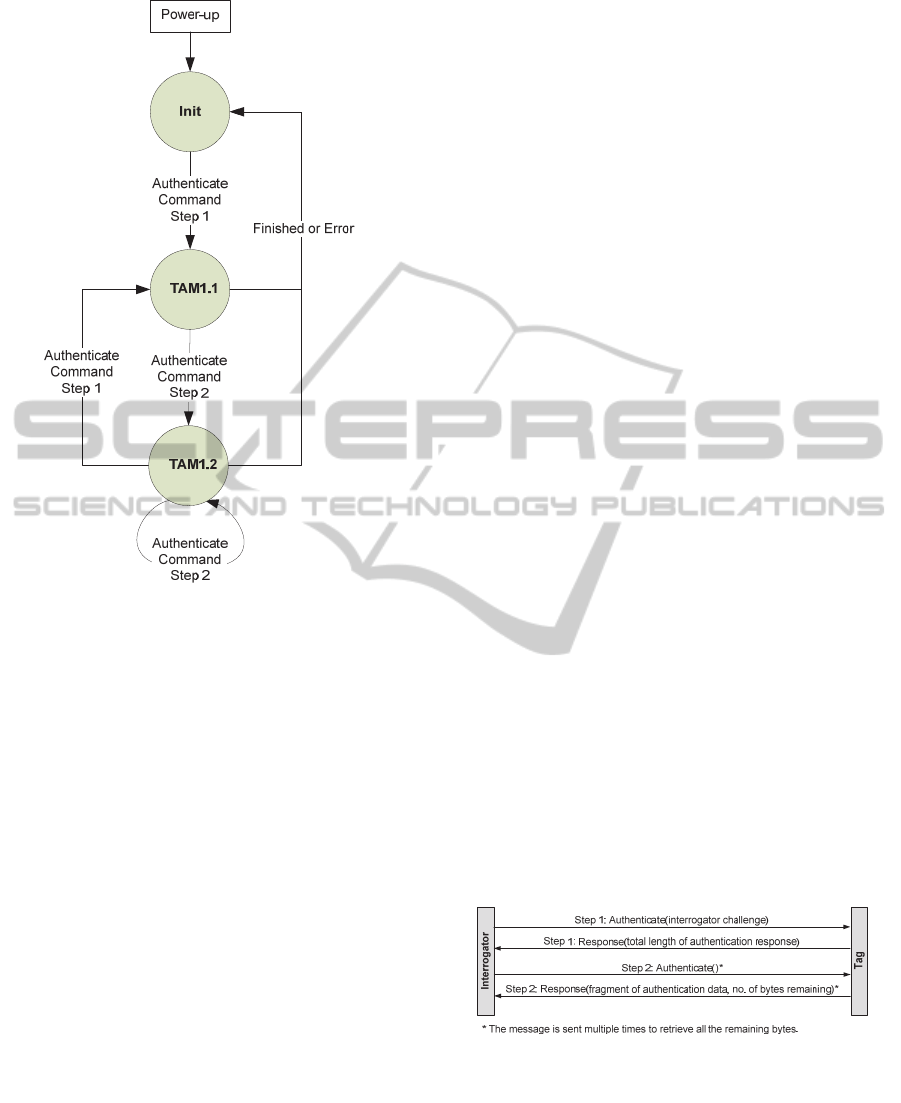
Figure 4: Tag state diagram.
2.5.1 Tag State Diagram
The logical process flow as developed above is now
embedded into the framework as defined in WD
29167-1. In accordance with the working draft the
tag can assume the states as depicted in figure 4.
A sequence of Authenticate commands needs to
be sent to the tag to complete a full tag authentica-
tion protocol. For a successful authentication the
entire sequence needs to be executed successfully.
The crypto suite state transitions triggered by the
authentication payloads are summarized in the next
subsection below. State transitions and tag responses
are according to the payloads of the Authenticate
command sent by the interrogator.
The processing of the Authenticate command
may include generation of an authentication crypto-
gram that will be returned in the tag’s response; the
tag may also return some buffered data. Because the
authentication protocol produces the output data
consecutively in the correct order, it is advantageous
to split the response in small pieces and to return
these pieces in parallel to the ongoing calculation.
After power-up the tag transitions to the ‘Init’
state. Once the tag receives an Authenticate com-
mand with payload for step 1, it processes the com-
mand, sends the response and transitions to TAM1.1
expecting an Authenticate command with payload
for step 2. When the tag receives the first Authenti-
cate command for step 2, it processes the command,
sends the response and remains in TAM1.2 as long
as there are authentication data bytes remaining to
be sent. In TAM1.2 the interrogator sends as many
Authenticate commands as required to fetch the
entire authentication data produced by the tag.
The interrogator indicates the length of the au-
thentication cryptogram in the payload of the Au-
thenticate command for step 1. The tag indicates the
number of bytes still available to fetch in the pay-
load of the response message.
Whenever the tag receives an Authenticate
command with payload for step 1, it resets all varia-
bles, transitions to TAM1.1 and starts processing the
command. The tag transitions to Init state once it has
sent out the last fragment of authentication crypto-
gram.
In case of failure during one of the steps of the
protocol, the crypto suite transitions to the ‘Init’
state.
When Rabin-Montgomery encryption and I/O
are overlapping in the tag there can be a couple of
short response packets from the tag, the exact behav-
iour being dependent on tag firmware optimization.
In any case, the final packet carries a success status
word in its payload or an error indicator, if applica-
ble.
2.5.2 Tag Authentication
The sequence of exchanged messages for tag authen-
tication is depicted in figure 5. The first message
includes a random challenge generated by the inter-
rogator and sent to the tag. The tag response is an
encrypted message that only the legitimate interro-
gator can decrypt, since it possesses the necessary
private key.
Figure 5: Message exchange for tag authentication.
In Step 1, the interrogator challenge is delivered
to the tag. This message is used to request the tag to
perform authentication. The response to this mes-
sage returns only the number of bytes to expect. In
Step 2, the interrogator retrieves the data fragments
by chaining further Authenticate commands and
responses. Once the interrogator has fetched the en-
SecureUHFTagswithStrongCryptography-DevelopmentofISO/IEC18000-63CompatibleSecureRFIDTagsand
PresentationofFirstResults
9

tire authentication record it is able to authenticate
the tag.
If the tag receives a message that is not formatted
as described in the following section it shall respond
with an error code and transition to ‘Init’ state.
2.5.3 Authentication Command
The authentication is performed in two distinct
steps. In step 1 of the Authenticate command the
interrogator sends a 10 byte random challenge to the
tag as indicated in the specification of the cipher.
As the tag cannot process the authentication
within the response timeout, it answers with a mes-
sage indicating the expected size of the Ramon-
Montgomery encrypted cipher test. The tag assumes
state TAM1.1 and begins the calculation of the ci-
pher.
In order to fetch the result, the interrogator issues
step 2 of the Authenticate command after some
time. The tag assumes state TAM1.2 and responds
with the first fragment of the resulting message, to-
gether with an indication of the number of bytes
missing. The size of the fragment returned is deter-
mined by the progress of message calculation and
the maximum which can be transferred in a single
message.
If there are message bytes remaining in the tag,
the interrogator waits a while and then repeats Au-
thenticate for step 2 until the response from the tag
indicates that the message is complete and that no
more data is available from the tag. Now the interro-
gator begins with message processing.
2.6 Tag Life Cycle and Key
Management
We will now briefly discuss aspects of the tag’s life
cycle, the key management, and the roles involved.
In figure
6 we can see the System Integrator and the
Tag Issuer shown as different roles. In this scenario
the System Integrator owns the asymmetric key pair
K
E
, K
D
(the RAMON encryption and decryption
keys), marked with blue and red colour, respectively
(in b/w print these keys show up as grey and dark
grey). The System Integrator hands over the public
key K
E
to the Tag Issuer.
Now the Tag Issuer produces a couple of tags
with uniquely generated tag IDs and signs them with
its private signature key K
S
. The signature key pair
is marked with light yellow colour (or light grey).
Note that the generation of tag ID signatures is op-
tional. In each tag the Tag Issuer stores the (signed)
tag ID and the Ramon encryption key K
E
. No secret
key needs to be stored in the tag.
In addition the Tag Issuer gives the signature
verification key K
V
and a list of (signed) tag IDs to
the System Integrator. Now the System Integrator
can verify the authenticity of this ID list.
The System Integrator sets up Interrogator sites
with a secure store containing the tag IDs and the
private RAMON decryption key KD. Thus the Inter-
rogator can decrypt the RAMON messages, identify
the tag and eventually authenticate it if the signature
matches.
Figure 6: Tag Life Cycle and Key Management.
SENSORNETS2013-2ndInternationalConferenceonSensorNetworks
10

3 PRELIMINARY PROTOTYPE
The authentication protocol specified so far requires
modified tags which support the secure authentica-
tion procedure, but it also requires UHF interroga-
tors which implement the Authenticate command
that is still in the standardisation process. However,
such an interrogator is currently not available.
For that reason it is necessary to emulate the be-
haviour of the secure UHF tag on hardware which is
compatible with the current ISO/IEC 18000-6 Type
C standard and use commands which are available in
this standard.
In order to achieve maximum flexibility in the
implementation of cryptographic functions we de-
cided to extend a standard state machine controlled
UHF tag with a microprocessor. Both units are
closely coupled with shared volatile memory which
permits the microcontroller to receive messages via
the UHF channel and to return responses.
3.1 Hardware Description
In order to provide a smooth migration path we
started with an already existing standard UHF tag.
This device, when mounted on a PCB, can com-
municate its digital data stream to an external device
and can backscatter the data received from that de-
vice. Thus the function of the former UHF tag is
reduced to an analogue front end (AFE).
The switch from autonomous mode of the tag to
AFE mode is made by means of a command se-
quence sent to the tag’s state machine from the at-
tached device via an I²C bus specially provided for
that purpose.
The attached device is represented by a Spartan 6
FPGA which is located on a suitable evaluation
board where the connections to the external world
are provided. The whole setup is shown in figure
7.
Within the FPGA the state machine for an
ISO/IEC 18000-6 Type C compliant tag is replicat-
ed, but with some modifications which facilitate the
implementation of the secure functions presented in
this paper
In the FPGA prototype all memory is provided as
non-persistent RAM.
3.2 Add-ons for Security Functions
The additional processing elements represented in
the FPGA comprise a Texas Instruments MSP430X
compatible CPU together with a couple of periph-
erals which are also compatible with the original
peripherals to some extent. The most important one
of these peripherals for our purpose is a hardware
multiplier capable of calculating a 32 bit result of a
16
16 bit integer multiplication within one clock
cycle. By using the multiply-add mode of this multi-
plication unit it is possible to implement the long
integer arithmetic functions required for Public Key
cryptography in a very efficient way.
Another valuable peripheral for strong cryptog-
raphy is an AES coprocessor capable of supporting
all the three standardised key sizes, i.e. 128, 129,
and 256 bits.
Other peripherals comprise a timer and a couple
of free programmable port bits. One of these bits is
used to generate serial output which can be dis
Figure 7: FPGA board and analogue front end.
SecureUHFTagswithStrongCryptography-DevelopmentofISO/IEC18000-63CompatibleSecureRFIDTagsand
PresentationofFirstResults
11

played in a terminal window on the controlling PC.
The microprocessor itself is controlled through a
special USB-to-I²C interface from a debugger run-
ning on the PC.
The MSP430X currently runs at a clock rate of
1,25 MHz which is significantly below the maxi-
mum speed for this processor architecture. The
speed was chosen to achieve command execution
performance close to that when a final tag design has
to operate in a power-limited environment.
3.3 Tag-CPU Communication
The tag (i.e. the part within the FPGA which is
based on the ISO/IEC 18000-6 Type C state ma-
chine) and the CPU are loosely coupled by means of
a common memory buffer of 128 16-bit words
which is within the address space of the tag’s state
machine. Specifically, it is located within the TID
(tag ID) memory bank.
The CPU can access (read and write) all the tag
memory by means of a special peripheral memory
access controller which also solves the task of arbi-
tration in case of conflicting access attempts. The
access rules are simple:
After the CPU posted a request for a specific
address, it has to wait for an interrupt which
signals the access grant.
If the tag tries to access the memory while the
CPU has access, it is delayed until the CPU is
done. This may sometimes lead to a timeout
on the tag’s air interface.
In all other cases the tag state machine and the
CPU may run independently.
Whenever the tag writes to a specific address in-
to the TID bank, a specific interrupt is generated for
the CPU to signal that a command message was re-
ceived over the air interface. This mechanism facili-
tates the CPU to stay in a power-save sleep state
most of the time until it has to respond to an external
request.
3.4 Over the Air Data Transfer
As we saw above any data from outside the CPU has
to be passed across the communication buffer in the
TID bank. The ISO/IEC 18000-6 Type C standard
defines (sometimes optional) commands to serve
this purpose.
For reading data from the communication buff-
er the Read and BlockRead commands are
available. The first reads a single 16 bit word
from a specific address while the latter trans-
fers a specified number of such words from
adjacent locations.
For writing data from outside into the commu-
nication buffer the commands Write and
BlockWrite are provided in the standard.
There is an issue with BlockWrite though: as any
ISO/IEC 18000-6 Type C command has to be com-
pleted within 20 ms, this may be too short for writ-
ing to an extended number of E²PROM cells within
a single command. As standard tags normally use
this memory type, they often do not support Block-
Write, or only with a length of just a single word.
This situation is completely different for a RAM
buffer.
Our prototype is currently confined to use
BlockRead for reading from the tag and repeated
Write for writing to the tag.
3.5 The Transport Protocol
In the proposed preliminary setup any messages be-
tween the interrogator and the tag’s CPU have to be
passed through the shared memory. In order to fa-
cilitate this transfer the transport protocol T=1 which
is widely used in the smart card environment was
chosen.
Although this protocol introduces some over-
head, it provides a couple of useful features, like
consistency checking with repetition of messages if
necessary, buffer size negotiation, chaining of long
messages, and others.
3.6 The Application Protocol
The application protocol layer is also taken from the
smart card domain as specified in ISO/IEC 7816. In
this standard an application protocol data unit
(APDU) comprises a class byte, an instruction byte,
two parameter bytes, an optional length specification
followed by the indicated number of data bytes, and
eventually an optional specification of the expected
response size. This makes up a command message.
Response messages comprise the response data,
if any, followed by a two-byte status word.
In the ISO/IEC 7816 paradigm the smart card or
secure token or, in our case, the secure UHF tag al-
ways takes the role of a server while the interroga-
tor, or rather the device which controls the interroga-
tor, takes the role of a client. Thus, during a message
sequence, the secure UHF tag receives a command
APDU, processes the command, and eventually re-
turns a response APDU.
SENSORNETS2013-2ndInternationalConferenceonSensorNetworks
12

3.7 Secure Messaging
Within the authentication method as proposed for WD
29167-1 in a previous section, the confidential and
authentic exchange of arbitrary data is not envisaged.
However, in some applications it is desirable to
communicate in a secure manner which is known as
secure messaging. Basically there are two stages of
secure messaging which can be applied separately or
combined.
Message Authentication: this ensures the in-
tegrity of a message, No one other than the
originator can generate or alter such a message
after a message authentication code (“MAC”)
is attached to the message, nor can the origina-
tor deny his authorship. The MAC is calculat-
ed over that part of the message which is to be
secured.
Message Encryption; this ensures the confi-
dentiality of a message. Only the originator
and the receiver of the message can see its
clear content.
As mentioned, both security mechanisms can be
combined. In that case the state of the art requires
applying the encryption first and message authenti-
cation afterwards.
For both security mechanisms a number of cryp-
tographic algorithms are available. In our prototype
we used AES-CBC-128 for the encryption and AES-
CMAC- 128 for message authentication. This choice
was based on the availability of coprocessor support
for the AES crypto-primitive.
4 RESULTS
With the FPGA setup we were able to execute a se-
cure authentication test suite comprising a Rabin-
Montgomery authentication of the tag, followed by
an AES based mutual authentication, writing a data
record with secure messaging (encrypted and au-
thenticated), and then securely reading back the data
just written.
With the microprocessor running at a clock rate
of 1.25 MHz we obtained satisfactory results.
Thanks to the integrated multiplication unit the Rab-
in-Montgomery authentication with a modulus of
1024 bit size was performed within 134 ms. This
does not include the time required to transmit the
result to the interrogator which takes more than
330 ms. The buffer determines if the components
involved require the authentication message to be
split into at least two fragments, which adds to the
communication times. However, we do not expect to
have buffers big enough to transfer the whole mes-
sage within a single block.
The performance of the secure messaging tests
was less satisfactory. This was due to the fact that a
BlockWrite command with sufficient data length
was neither supported by our AFE nor by the UHF
reader firmware. Therefore, we had to fall back to an
appropriate number of Write commands which im-
posed a considerable time overhead. Thanks to the
AES coprocessor, the AES-based encryptions were
calculated with considerable performance as ex-
pected,. However, overall execution times were
dominated by the communication.
5 CONCLUSIONS
As we expect the standardisation to take some time
we will continue to experiment with setups based on
the shared memory approach taken with the FPGA.
For further evaluations and estimations on power
consumption and operating range the FPGA should
be replaced with an ASIC implementing basically
the same functionality.
After the completion of ISO/IEC WD 29167 as a
standard and the availability of compatible readers we
will continue to implement this technology in order to
enhance the performance of secure UHF tags.
REFERENCES
Finkenzeller, Klaus, 2012: RFID Handbuch (RFID
Handbook), Hanser Verlag, Munich, 6th edition, ISBN
978-3446429925, http://rfid-handbook.de
ISO/IEC 18000-6, 2010: Information technology - Radio
frequency identification for item management - Part 6:
Parameters for air interface communications at 860
MHz to 960 MHz, International Organization for
Standardization, Geneva, Switzerland
ISO/IEC FDIS 18000-63, 2012: Information technology -
Radio frequency identification for item management -
Part 63: Parameters for air interface communications
at 860 MHz to 960 MHz Type C, International Or-
ganization for Standardization, Geneva, Switzerland.
Mendezes, Alfred J., van Oorschot, Paul C., Vanstone,
Scott A., 1997: Handbook of Applied Cryptography,
CRC Press, Inc., NewYork, ISBN 0-8493-8523-7.
Montgomery, Peter L: 1985. Modular Multiplication with-
out Trial Division. In Math. Computation, Vol. 44,
1985, p. 519–521.
Rabin, Michael O., 1979: Digitalized Signatures and Public-
Key Functions as Intractable as Factorization. In MIT-
LCS-TR 212, MIT Laboratory for Computer Science,
January 1979.
SecureUHFTagswithStrongCryptography-DevelopmentofISO/IEC18000-63CompatibleSecureRFIDTagsand
PresentationofFirstResults
13
