
Complex Plane Transformations for
Manipulation and Visualization of Panoramas
Leonardo Sacht and Luiz Velho
IMPA - Instituto Nacional de Matematica Pura e Aplicada, Rio de Janeiro, Brazil
Keywords:
Panoramic Images, Conformal Projections.
Abstract:
We present a method for manipulation and visualization of wide-angle images using transformations defined
on the complex plane C. We map the unit sphere S
2
to C using the stereographic projection, multiply the
complex plane by a given complex number, and map the result back to the sphere using the inverse of the
stereographic projection. Since all these transformations preserve angle, we obtain a result containing only
distortions due to the latitude/longitude representation of the sphere, which were already present in the input
image. We then explore the possibility given by our technique of mapping wide fields of view to narrower ones.
This makes possible to apply perspective projection to wider fields of view, leading to a natural generalization
of the perspective projection in the context of panoramic images. Our results are generated in real-time and
compare competitively with state-of-the-art methods used to project the viewing sphere to the image plane.
1 INTRODUCTION
Wide-angle images have become increasingly popular
during the last years due to the development of com-
putational photography techniques and equipment to
capture this kind of images. Although they represent
much better the information of a scene, they usually
present artifacts such as bending of straight lines.
A format commonly used to represent images
of the full sphere around a viewpoint is the equi-
rectangular format (Figure 1 (a), bottom). Each point
on the the viewing sphere is represented by its longi-
tude/latitude coordinates on the equi-rectangular im-
age. Thousands of images in this format are available
on the Internet, for example in (Flickr, 2012).
Our method allows the possibility of applying
conformal transformations to these images, i.e., trans-
formations that preserve angles on the sphere. Due to
this angle-preserving property, the resulting modified
equi-rectangular images (Figure 1 (d)) could be pro-
jected on a spherical surface such as a dome and the
perceived result would not present unpleasant distor-
tions. We see this possibility as a promising future
application of our technique.
Other possibility than projecting the modified
spherical image on a dome, is to apply some planar
projection and map it to a new image. It is well known
that the only projection that preserves all possible
straight lines in the scene is the perspective projection,
but it distorts objects for fields of view wider than 90
degrees. Our technique allows mapping a wide field
of view on the sphere to a narrower one, and then ap-
plying the perspective projection to this narrow field
of view (Figure 1 (e)). This process leads to high-
quality results, naturally extends the perspective pro-
jection and is very simple to implement in real-time,
making it possible to be incorporated to panorama
viewers such as Google Street View (Google Street
View, 2012) and fieldOfView (fieldOfView, 2012).
Incorporating our technique to these viewers would
improve the navigation offered by them, since their
visualization is limited to a narrow filed of view to
avoid the distortions of the standard perspective pro-
jection.
Figure 1 describes the pipeline of our method:
it receives as input an equi-rectangular image repre-
senting the full viewing sphere around a given view-
point (Figure 1 (a)). We map this sphere to the com-
plex plane using the stereographic projection (Figure
1 (b)), which is known to be conformal and surjective.
We then transform the complex plane by multiplying
each point by some given real number (Figure 1 (c)).
The transformation that we explore most is uniform
scaling of the complex plane, but our technique can
handle full spatially-varying Mobius transformations
as well. This transformed complex plane is mapped
back to the unit sphere using the inverse stereographic
projection, leading to a transformed equi-rectangular
179
Sacht L. and Velho L..
Complex Plane Transformations for Manipulation and Visualization of Panoramas.
DOI: 10.5220/0004197701790184
In Proceedings of the International Conference on Computer Graphics Theory and Applications and International Conference on Information
Visualization Theory and Applications (GRAPP-2013), pages 179-184
ISBN: 978-989-8565-46-4
Copyright
c
2013 SCITEPRESS (Science and Technology Publications, Lda.)
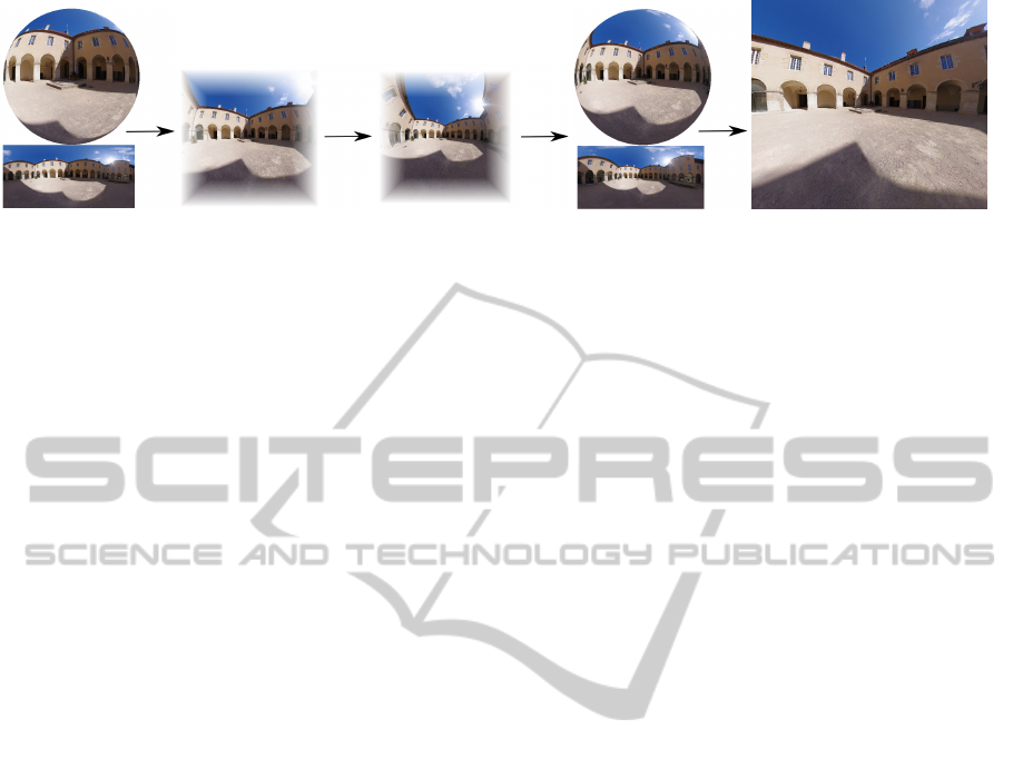
(a) (b) (c) (d) (e)
Figure 1: The input image of our method is a viewing spehre at a viewpoint, which is represented by an equi-rectangular
image (a). We map the sphere to the complex plane using the stereographic projection (figure (b) shows only a limited part
of the complex plane), apply a transformation to the complex plane (c) and map the result back to the sphere (d). Finally,
perspective projection is applied to the modified viewing sphere, allowing for visualization of wide fields of view with a good
balance between straight line and conformality (figure (e) shows a 160 degree field of view).
image (Figure 1 (d)). We then apply a perspective
projection to the resulting sphere (Figure 1 (e)).
All these transformations are independent for each
sphere vertex, allowing us to implement them in par-
allel and obtain real-time interaction. As a limitation,
our results may present straight line bending for some
scenes and especially for fields of view that are too
wide (wider than 180 degrees).
To summarize, the main contributions of our work
are the following:
• Use of complex transformations to map wide
fields of view on the sphere to narrower ones in
a conformal way;
• Generalization of the perspective projection to vi-
sualize wide-angle images real-time.
The rest of the paper is organized as follows:
in section 2 we review the panoramic image liter-
ature and relate previous works to ours; In section
3 we describe in detail our technique for manipula-
tion of equi-rectangular images and perspective re-
projection; in section 4 we present implementation
details; in section 5 we describe our results and com-
pare with previous works; Finally, in section 6 we de-
scribe limitations and possibilities for future work.
2 RELATED WORK
Due to their increasing popularity and interest,
panoramic images have become a theme of intense
discussion in the Computer Graphics and Image Pro-
cessing communities in the last twenty years.
The impossibility of obtaining a global projection
from the sphere to the plane that preserves all possible
straight lines and object shapes was shown in the sem-
inal work by Zorin and Barr (Zorin and Barr, 1995).
The alternative to this problem proposed in
(Zelnik-Manor et al., 2005) was to use different per-
spective projections in the same scene. In that work
the user specified different projection planes and view
directions to define the different projections. The dis-
continuities caused by using different projections for
different regions of the panorama were hidden (if pos-
sible) by choosing the projection planes in a way that
fit well orientation discontinuities that were already
present in the scene.
The work in (German et al., 2007) explored con-
formal mappings to preserve the shape of the objects
in a panoramic image. They investigated the stereo-
graphic projection and scaling of the complex plane
but only for artistic and exploratory purposes. Since
their focus was on shape preservation, their results
present bent lines. In our work we go beyond and im-
prove these ideas to map wide fields of view to nar-
rower ones and add a perspective re-projection step,
which allows for better quality results because the
straight lines are less bent.
Other methods relied on both user interaction and
energy-minimization formulations. (Carroll et al.,
2009) used the important lines in the scene provided
by the user and detected faces to control straight line
preservation and conformality in these regions. (Kopf
et al., 2009) used regions specified by the user where
the projection should be nearly planar to formulate
their optimization framework. In these methods, user
interaction was usually laborious and the optimiza-
tion formulations made them impossible to be imple-
mented in real-time.
Another important technique was proposed in
(Kopf et al., 2007). Their viewer changes the pro-
jection depending on the filed of view, what can be
achieved by our viewer by applying different scales to
the complex plane as the field of view of the perspec-
tive projection changes. But in our work, we let the
user specify both parameters, what gives her or him
more control. Also, our visualization simulates better
camera movements since it is a natural generalization
GRAPP2013-InternationalConferenceonComputerGraphicsTheoryandApplications
180
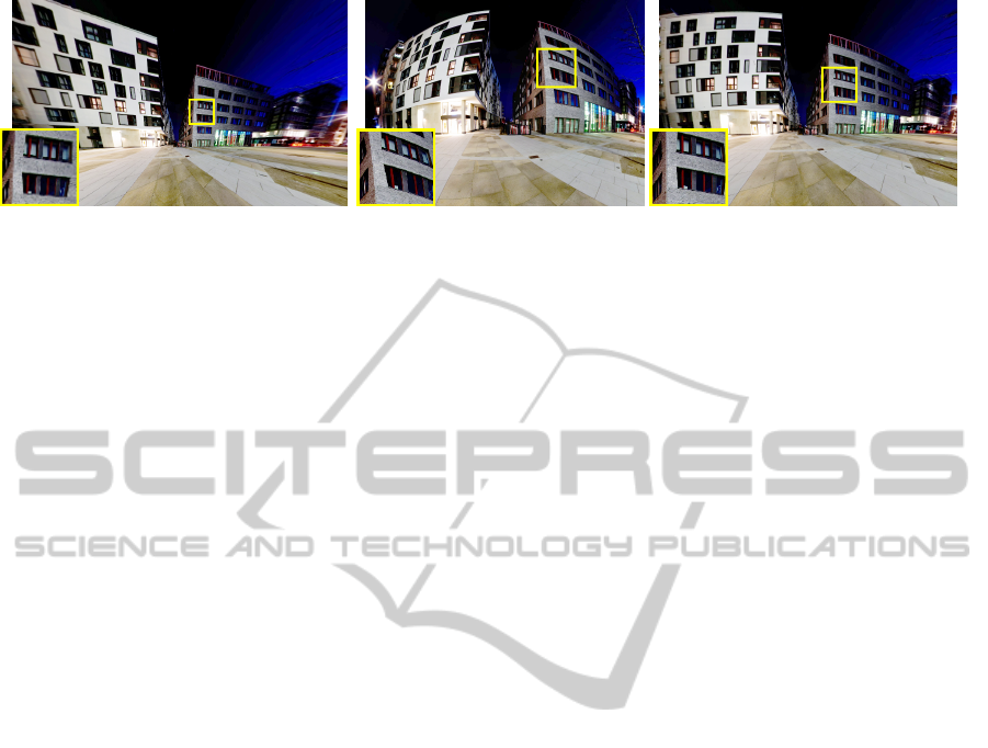
Figure 2: Left: perspective projection applied to a 160 degree field of view. Center: stereographic projection. Right: Our
result using the value s = 0.8 to scale the complex plane.
of the perspective projection.
Another advantage of our method compared to
previous ones is that we do not rely on heavy user
interaction. The user is only asked to vary the field
of view of the perspective projection and the scale to
be applied to the complex plane in our viewer, what
makes our panorama viewer a pleasant experience,
instead of laborious. Also, our formulation is sim-
ple and does not rely on heavy optimizations, which
makes our method possible to be implemented in real-
time. We elaborate more on comparisons with previ-
ous works in Section 5.
A work that is not related to panoramic images
but has some connection with ours is (Crane et al.,
2011). In this work, the authors look for conformal
transformations of surfaces by associating R
3
with
the imaginary part of the Quaternions Im(H). We
work with the complex plane C instead of Im(H),
since our surface of interest is the unit sphere S
2
and
S
2
\{(0, 0, −1)} is confomally equivalent to the com-
plex plane. Applying their work to our context would
produce conformal results, but straight lines in the
scene would appear bent.
3 METHOD
In this section we explain details of our method to ma-
nipulate equi-rectangular images and visualize them
with less distortions. We first give an overview and
motivation of our technique and then we present the
Mathematics involved in each transformation of our
pipeline.
3.1 Overview
The importance of conformal mappings is well known
in geometry applications. Intuitively, a mapping from
a surface to another is conformal if it is locally a com-
position of a scale and a rotation. This property pre-
vents the map to shear the surface, an important prop-
erty for mesh quality and texture mapping of the final
surface (for more details, see the work (Crane et al.,
2011)). Regarding panoramic images, conformality is
also essential (Carroll et al., 2009).
In this work, we apply a sequence of conformal
transformations to a given viewing sphere. The only
transformation that is not conformal is the final per-
spective projection. Although this seems to be a prob-
lem, we apply this final mapping to a narrow field
of view of the (conformally) transformed sphere, and
perspective projection does not deviate too much from
conformality for narrow fields of view. The sequence
of transformations we use is described in Figure 1 and
detailed in the next sub-section.
The choices we have made in our method are justi-
fied in Figure 2. We first show the results of applying
the perspective (left) and stereographic (center) pro-
jections to a 160 degree field of view. The first result
preserves straight lines but presents excessive shear-
ing especially in the periphery of the image. On the
other hand, the stereographic projection is conformal,
but lines are clearly bent. We propose to combine the
good properties of both methods. We first observe in
the detail of Figure 2 (left) that the perspective projec-
tion is almost conformal for narrow fields of view. By
applying the sequence of conformal transformations
described in Figure 1 using the value s = 0.8 to scale
the complex plane, we are able to map 160 degree
FOV to a narrower FOV and then apply perspective
transformation to this narrow field of view. Figure 2
(right) shows the final result of our method.
We leave to the user the specification of the field
of view of the original sphere to visualized and the
scale of the complex plane to be applied. Of course,
we recommend that these parameters are such that the
final perspective projection is applied to a narrow field
of view.
3.2 Transformations
We first map the unit sphere to the complex plane us-
ing the stereographic projection, which is illustrated
in Figure 1 (b). This projection consists of map-
ComplexPlaneTransformationsforManipulationandVisualizationofPanoramas
181

ping each point on S
2
\{(0, 0, −1)} to the z = 1 plane
through lines emanating from the pole opposite to the
point of tangency (0, 0, −1), for which the projection
is not well-defined. The expression for this projection
is given by:
S : S
2
\{(0, 0, −1)} → C
(x, y, z) 7→ (u, v) =
2x
z+1
,
2y
z+1
(1)
It is well known that the stereographic projection is
a conformal mapping from the sphere to the complex
plane (Snyder, 1987).
The next step of our method is to multiply the
complex plane by some given complex number. We
first write the points in their polar form
u + iv = (u, v) 7→ (
√
u
2
+ v
2
, arctan2(u, v)) =
= (r, θ) = re
iθ
(2)
In this form, multiplication by a given complex num-
ber se
iα
is given by the simple expression
(r, θ) 7→ (˜r,
˜
θ) = (rs, θ + α) (3)
From complex analysis (Conway, 1978), it is known
that multiplication by a complex number is a confor-
mal mapping from the complex plane onto itself. We
show in Fig. 1 (c) the effect of multiplying the plane
by 0.6, i.e., a uniform scale of 0.6 and no rotation.
Finally, we rewrite the complex plane in Cartesian
coordinates
(˜r,
˜
θ) 7→ ( ˜u, ˜v) = (˜r cos(
˜
θ), ˜r sin(
˜
θ)) (4)
and map the transformed points back to the unit
sphere using the inverse stereographic projection,
which is also conformal:
S
−1
: C → S
2
\{(0, 0, −1)}
( ˜u, ˜v) 7→
4 ˜u
˜u
2
+ ˜v
2
+4
,
4 ˜v
˜u
2
+ ˜v
2
+4
,
˜u
2
+ ˜v
2
−4
˜u
2
+ ˜v
2
+4
(5)
The result of this transformation is presented in Fig-
ure 1 (d).
At this point we have a modified viewing sphere
containing the information of a wide FOV represented
in a narrower one. Since all the manipulations per-
formed until now were conformal, one could project
this modified sphere in a spherical surface such as a
dome and see it without angle distortions, allowing
for acceptable visualizations of wide fields of view on
a dome.
In this work we apply a perspective transforma-
tion to the modified sphere, in order to see it in a flat
surface such as a computer screen:
P : S
2
\{z < 0} → C
(x, y, z) 7→
x
z
,
y
z
. (6)
The result of this projection is shown in Figure 1 (e).
4 IMPLEMENTATION
To implement all the transformations we have just
described, we represent the unit sphere as a triangle
mesh. Since all operations from (1) to (6) can be per-
formed independently for each vertex on the mesh, we
implemented them as a GLSL vertex shader.
The shader is loaded by a Qt Viewer Application
that implements our technique. This application con-
sists of an interface where the user specifies the view
direction, the field of view of the input viewing sphere
to be visualized and the scale to be applied to the com-
plex plane. The interface also has an option to cal-
culate a good scale value depending on the specified
field of view, so the user specifies only one of the two
parameters.
To illustrate the real-time performance of our
viewer, we show some timing numbers in Table 1.
All these numbers were generated with a screen res-
olution of 1024 ×768 pixels in a PC with an Intel
Xeon Quad Core 2.13GHz and 12 GB of RAM and
a GeForce GTX 470 GPU. We emphasize that mesh
and image resolutions shown in Table 1 generate vi-
sualizations without discretization artifacts.
Table 1: Frame rates generated by our technique while the
user interacts, for different mesh resolutions (vaying on the
rows) and different equi-rectangular panorama image reso-
lutions (varying on the columns).
Vertices \ Pixels 4000 ×2000 8000 ×4000
200 ×200 93 fps 89 fps
400 ×400 85 fps 84 fps
800 ×800 35 fps 33 fps
5 RESULTS AND DISCUSSION
In the accompanying video of this paper we show
three results of our technique. The first one shows
the effect of applying different scales to the view-
ing sphere, without applying a perspective transfor-
mation. The proportions of the objects in the equi-
rectangular image change due to the scaling param-
eter, but the angles are well preserved. We also ob-
serve that the transformations are bijective, i.e., the
whole content of the sphere appear in all transformed
results.
The next two results in the accompanying video
show the result of applying a scale to the sphere, fol-
lowed by a perspective transformation. Our interface
allows the user to look around the sphere and control
the field of view and scaling factor. In both results, we
zoom out until the perspective projection (our result
with scale s = 1) becomes too stretched. To correct
GRAPP2013-InternationalConferenceonComputerGraphicsTheoryandApplications
182
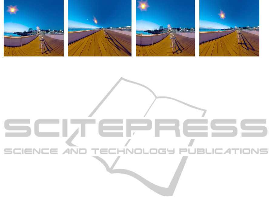
(a) Equi-rectangular (b) Perspective (c) Mercator (d) Ours, s = 0.75
Figure 3: Comparison with standard projections for a 160 degree field of view. Our result is the only one with a good balance
between straight line and object shape preservation.
this problem, we decrease the scale s which makes
possible to see a much wider field of view with less
distortions. We observe that the FOV shown in the
video is the one used to define the perspective pro-
jection on the modified viewing sphere, which is not
the same as the original viewing sphere. For instance,
when we have a FOV of 130 degrees and s = 0.5 we
are seeing a FOV wider than 180 degrees in the origi-
nal sphere.
We also compare our method with standard pro-
jections to map the sphere to the image plane in Fig-
ure 3. We observe that for the field of view of 160
degrees the perspective projection (b) distorts objects
too much but preserves all straight lines. On the other
hand, Mercator (c) projection preserves object shapes
because it is conformal, but bends lines. The result
obtained with our method (d) using a scale parameter
s = 0.75 is the only one that presents a good balance
between these two properties.
Finally, we compare our method with recent
works on the same topic in Figure 4. The result ob-
tained by the technique proposed in (Zelnik-Manor
et al., 2005) (a) shows discontinuities on the floor pro-
duced by using different projections for different ar-
eas of the image. This strategy works successfully for
the building in the image, since these discontinuities
are hidden by natural discontinuities in the scene, but
it fails to fit the geometry of the floor. In Fig. 4 (b) we
show a result produced by our implementation of the
technique in (Carroll et al., 2009). All straight lines
specified by the user (please see their work for more
details) are well-preserved, but the lines on the floor
appear bent, since they are too many to be marked by
the user. Although their energy minimization formu-
lation guarantees conformality and smoothness of the
final result, it has the problem of taking some seconds
to be performed. Our result ((c), for which we apply
a scale s = 0.8 to the complex plane) does not rely on
heavy user interaction nor on any optimization and is
not restricted to scenes with any particular geometry.
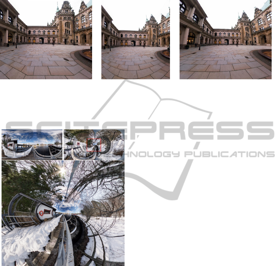
6 LIMITATIONS AND FUTURE
WORK
A limitation of our method appears when one uses our
interface to visualize too wide fields of view (Figure
5). Applying standard perspective projection (s = 1)
is prohibitive in this case, and applying a small scale
to the complex plane makes the final result of our
method deviate too much from the standard perspec-
tive projection and present bent lines. One possibility
to overcome this limitation would be to apply content-
dependent scale to the complex plane, i.e., regions
with straight lines would be forced to have a scaling
parameter close to 1. However, the specification of
important lines in the scene could be laborious, as al-
ready happened in previous works.
We also intend to use our technique to map wide
fields of view to narrower ones and project the re-
sulting viewing sphere on a spherical dome, instead
of applying a planar perspective projection as we de-
scribed in Section 3. This visualization would not
have the distortions caused by the planar projections,
and would benefit from our conformal pipeline.
Another interesting direction for future work is to
extend our technique to panoramic videos, i.e., tem-
porally varying viewing spheres. Distortions as the
ones observed in (Sacht et al., 2011) would have to be
considered and a time-varying warping could have to
be formulated.
Since the technique we have presented in this pa-
per is simple and can be implemented in real-time,
we think it can be easily incorporated to current
panorama viewers such as Google Street View.
ACKNOWLEDGEMENTS
The first author thanks CNPq for the financial sup-
port. The authors thank the following Flickr users
ComplexPlaneTransformationsforManipulationandVisualizationofPanoramas
183
(a) (Zelnik-Manor et al., 2005) (b) (Carroll et al., 2009) (c) Ours, s = 0.8
Figure 4: Comparison with other methods to project the viewing sphere to the image plane for a field of view of 150 degrees.
In the result obtained by the method in (Zelnik-Manor et al., 2005) (a), the different perspective projections used for different
areas of the image appear clear and unpleasant on the floor of the scene. The method by (Carroll et al., 2009) (b) preserves
all straight lines marked by the user, but fails to preserve the ones on the floor (which are too many to be marked by the user).
Our result (c) has all straight lines in the scene with very little bending.
Figure 5: Top-left: input equi-rectangular image. Top-
right: result of applying a scale s = 0.05 on the viewing
sphere. Bottom: result of perspective projection applied to
the transformed viewing sphere (showing only the area in-
side the red rectangle of the top-right figure). Although al-
most the entire viewing sphere is being shown, unpleasant
straight line distortions appear.
for making available their images under the Creative
Commons license: Janne., gadl and HamburgerJung.
REFERENCES
Carroll, R., Agrawal, M., and Agarwala, A. (2009). Opti-
mizing content-preserving projections for wide-angle
images. In ACM SIGGRAPH 2009 papers, SIG-
GRAPH ’09, pages 43:1–43:9, New York, NY, USA.
ACM.
Conway, J. B. (1978). Functions of One Complex Variable.
Springer-Verlag, New York.
Crane, K., Pinkall, U., and Schr
¨
oder, P. (2011). Spin trans-
formations of discrete surfaces. ACM Trans. Graph.,
40.
fieldOfView (2012). Interactive panoramas - fieldofview.
http:// fieldofview.com/panoramas.
Flickr (2012). Flickr: Equirectangular. http://
www.flickr.com/groups/equirectangular/.
German, D. M., Burchill, L., Duret-Lutz, A., Prez-Duarte,
S., Prez-Duarte, E., and Sommers, J. (2007). Flat-
tening the viewable sphere. In Cunningham, D. W.,
Meyer, G. W., Neumann, L., Dunning, A., and Pari-
cio, R., editors, Computational Aesthetics, pages 23–
28. Eurographics Association.
Google Street View (2012). Street view - google maps.
http:// maps.google.com/streetview.
Kopf, J., Lischinski, D., Deussen, O., Cohen-Or, D., and
Cohen, M. F. (2009). Locally adapted projections to
reduce panorama distortions. Comput. Graph. Forum,
28(4):1083–1089.
Kopf, J., Uyttendaele, M., Deussen, O., and Cohen, M. F.
(2007). Capturing and viewing gigapixel images. In
ACM SIGGRAPH 2007 papers, SIGGRAPH ’07, New
York, NY, USA. ACM.
Sacht, L., Velho, L., Nehab, D., and Cicconet, M. (2011).
Scalable motion-aware panoramic videos. In SIG-
GRAPH Asia 2011 Sketches, SA ’11, pages 37:1–
37:2, New York, NY, USA. ACM.
Snyder, J. P. (1987). Map projections – a working manual.
Technical Report 1395, U. S. Geological Survey.
Zelnik-Manor, L., Peters, G., and Perona, P. (2005). Squar-
ing the circles in panoramas. In Proceedings of
the Tenth IEEE International Conference on Com-
puter Vision - Volume 2, ICCV ’05, pages 1292–1299,
Washington, DC, USA. IEEE Computer Society.
Zorin, D. and Barr, A. H. (1995). Correction of geomet-
ric perceptual distortions in pictures. In Proceedings
of the 22nd annual conference on Computer graph-
ics and interactive techniques, SIGGRAPH ’95, pages
257–264, New York, NY, USA. ACM.
GRAPP2013-InternationalConferenceonComputerGraphicsTheoryandApplications
184
