
Joint Segmentation and Tracking of Object Surfaces in Depth Movies
along Human/Robot Manipulations
Babette Dellen, Farzad Husain and Carme Torras
Institut de Rob
`
otica i Inform
`
atica Industrial, CSIC-UPC, Llorens i Artigas 4-6, 08028 Barcelona, Spain
Keywords:
Range Data, Segmentation, Motion, Shape, Surface Fitting.
Abstract:
A novel framework for joint segmentation and tracking in depth videos of object surfaces is presented. Initially,
the 3D colored point cloud obtained using the Kinect camera is used to segment the scene into surface patches,
defined by quadratic functions. The computed segments together with their functional descriptions are then
used to partition the depth image of the subsequent frame in a consistent manner with respect to the precedent
frame. This way, solutions established in previous frames can be reused which improves the efficiency of
the algorithm and the coherency of the segmentations along the movie. The algorithm is tested for scenes
showing human and robot manipulations of objects. We demonstrate that the method can successfully segment
and track the human/robot arm and object surfaces along the manipulations. The performance is evaluated
quantitatively by measuring the temporal coherency of the segmentations and the segmentation covering using
ground truth. The method provides a visual front-end designed for robotic applications, and can potentially be
used in the context of manipulation recognition, visual servoing, and robot-grasping tasks.
1 INTRODUCTION
During human or robotic manipulations, we face the
challenge of having to interpret a large amount of vi-
sual data within a short period of time. The data from
the sensors needs to be structured in a way that makes
task-relevant visual information more accessible. The
recognition of objects and scene context in a tempo-
rally consistent manner plays here a central role.
Moreover, in manipulation tasks, the use of 3D in-
formation is of particular importance, since accurate
grasping and object manipulation require knowledge
about both the 3D shape of the objects and their 3D
context, e.g., to avoid collisions. For depth acquisi-
tion, stereo set-ups, laser-range scanners, or time-of-
flight depth sensors are commonly used. Recently, the
release of the Kinect camera (Kinect, 2010), a depth
sensor based on a structured light system, has opened
new possibilities for acquiring depth information in
real time.
A traditional way to process the visual data in ma-
nipulation tasks is to use geometric models for recog-
nizing objects in the image and to track them using
conventional tracking paradigms along the manipula-
tion (Kragic, 2001). In this case, exact object models
need to be defined prior to the task, which, consid-
ering the variability of an object’s appearance in the
image, has the drawback that the system may not eas-
ily adapt to new scenarios.
In this work, we approach the problem from a dif-
ferent angle. Our main contribution and aim is the
creation of consistent segmentations of depth images,
into geometric surfaces, along a depth video and the
tracking of segments along the movie. Starting from
a known initial segmentation of the first frame into
surface segments, we show in this paper how this in-
formation can be exploited in a consecutive frame to
group the current depth values into segments. This
way, information from the previous frame can be ef-
ficiently recycled, and segment labels can be kept
throughout the sequence, enabling tracking of surface
patches.
The robot can use such a representation to draw
conclusions about scene content (Aksoy et al., 2011),
to guide its own movements (visual servoing), or to
use surface information for the planning of grasping
movements (Taylor and Kleeman, 2002), or even in
a learning-by-demonstration context (Agostini et al.,
2011; Rozo et al., 2011). At a later stage, higher-level
information about objects may enter the task by de-
scribing objects through their composite 3D surfaces
(Hofman and Jarvis, 2000).
The paper is structured as follows: In Section II,
we discuss related work. The proposed algorithm is
244
Dellen B., Husain F. and Torras C..
Joint Segmentation and Tracking of Object Surfaces in Depth Movies along Human/Robot Manipulations.
DOI: 10.5220/0004209502440251
In Proceedings of the International Conference on Computer Vision Theory and Applications (VISAPP-2013), pages 244-251
ISBN: 978-989-8565-47-1
Copyright
c
2013 SCITEPRESS (Science and Technology Publications, Lda.)

introduced in Sections III-IV. Then, in Section V, the
results for different human/robot manipulations are
presented. Future work is sketched in Section VI.
2 RELATED WORK
Joint segmentation and tracking has previously
been performed mostly for color image sequences
(Abramov et al., 2010; Deng and Manjunath, 2001;
Patras et al., 2001; Wang, 1998; Wang et al., 2009;
Grundmann et al., 2010). In a recent work, the color
images were segmented by finding the equilibrium
states of a Potts model (Abramov et al., 2010). Con-
sistency of segmentations obtained along the movie
and the tracking of segments were achieved through
label transfer from one frame to the next using optic
flow information. This way, the equilibrium states in
the current frame could be encountered more rapidly.
The resulting segments represent regions of uniform
color and usually do not coincide with the object sur-
faces in a geometric sense, which we would desire for
our system. The solutions found by Abramov et al.
(2010) cannot be easily adapted to our problem, be-
cause color segmentation and depth segmentation are
inherently different problems. Surfaces cannot be de-
fined based on local properties only, which increases
the difficulty of the problem considerably.
Other methods for video segmentation are usually
performing independent segmentations of each frame
and then try to match segments (Deng and Manjunath,
2001; Patras et al., 2001; Wang, 1998; Grundmann
et al., 2010). This is problematic because segmen-
tations have to be computed from scratch for every
frame, which has consequences on both the computa-
tional efficiency of the method and the temporal con-
sistency of the results. For cluttered scenes, the par-
tition of the segmentation tends to change from one
frame to the next, and temporal coherence of the seg-
mentations is prone to be impaired because of this ef-
fect.
In another work, segmentation and multi-object
tracking were performed simultaneously using graph-
ical models (Wang et al., 2009). Observed and hid-
den variables of interest describing the appearance
and the states of objects are jointly considered and
used to formulate the objective as a Markov random
field energy minimization problem. Different from
our method, depth measurements do not enter the
framework, and objects are defined based on their 2D
appearance alone. Also, objects of interest are de-
fined in the first frame and are then tracked along the
sequence. While the method delivers convincing re-
sults, energy minimization is computationally expen-
sive and efficient optimizations would have to be de-
veloped to make the approach more practical.
To the authors’ knowledge, little work has been
done in this field using depth information as the
primary vision cue for segmentation and tracking.
Parvizi and Wu performed multiple object tracking
using an adaptive depth segmentation method (Parvizi
and Wu, 2008). Time-of-flight depth was used to seg-
ment each frame independently by finding the con-
nected components based on an absolute depth dis-
tance measure. The segments of adjacent frames were
then associated with each other using a depth his-
togram distribution. However, this depth segmenta-
tion method is rather simple and does not partition the
data into distinct surfaces. As a consequence, bound-
aries defined by changes in 3D shape (curvature) can-
not be detected, which constitutes a major difference
in comparison to our method. In addition, each movie
frame is segmented from scratch. In the case of sur-
face segmentation, this can be rather costly. Further-
more, the temporal consistency of the segmentations
will degrade with increasing clutter in the scene.
In Lopez-Mendez et al. (2011), upper body track-
ing of a human using a range sensor (Microsoft
Kinect) is performed. Their technique is limited to
the human beings only as they use a prior model of
human body.
3 OVERVIEW OF THE METHOD
Our method for depth-video segmentation consists of
three parts: (i) Segment transfer and seeding, (ii) re-
estimation of surface models and grouping, and (iii) a
consistency check and respective re-grouping of pix-
els (see Fig. 1).
In the first part (i), labels of the depth image ob-
tained at frame F
t
are transferred to the next frame
F
t+1
. Surface models that have been fitted to the
depth of frame F
t
for all segments are transferred as
well. A seed is created for each label by comparing
the predicted depth with the measured depth in the
projected segment area. If the distance of the mea-
sured depth and model depth is smaller than a thresh-
old, the respective pixel is accepted and used as a seed
for constructing the full segment region in the current
frame.
In part (ii), the surface models are re-estimated for
each segment using the current depth values of the re-
spective seed. Non-seed points are grouped in con-
nected components, and then assigned to the closest
surface in the neighborhood. Connectedness of found
segments is evaluated, and the labeling is adjusted ac-
cordingly.
JointSegmentationandTrackingofObjectSurfacesinDepthMoviesalongHuman/RobotManipulations
245

Frame t Frame t+1
t → t+1
t+1 → t+2
Segment
Seed
Segment transfer
and seeding
Re-estimation of
surface models
and grouping
Consistency
check
Re-grouping
Segment
(step 3)
(step 4-6)
(step 7)
Figure 1: Schematic of the method. Segment regions ob-
tained for frame F
t
are transferred to frame F
t+1
. The
points lying inside a given segment region are compared
with the respective surface model, and only those points
which fit the surface model are marked as seed points of the
given segment in frame F
t+1
. Then, the surface parame-
ters of the respective segment model are re-calculated using
the depth values of the seed. Using these models, the depth
of points outside the seed region can be predicted for each
segment, and the remaining points are assigned to the clos-
est segment surface, taking some proximity constraints into
account. Finally, the obtained segmentation for frame F
t+1
is compared with the previous segmentation for frame F
t
.
Only if an inconsistency is detected, the affected segments
are re-grouped using region growing and shrinking until the
problem is resolved.
Finally, in part (iii), the temporal consistency of
segments along the video is checked. Because of the
high frame rate of the Kinect, it can be assumed that
changes between frames (at least in the given scenar-
ios) are small, implying that a segment cannot grow or
shrink out of proportion from one frame to the next.
In case that such a temporal consistency problem is
detected, the points of the affected segments are re-
grouped until the problem is resolved, using a clearly
defined termination criterion.
A Microsoft Kinect sensor along with the
Kinect package of ROS (Robot Operating Sys-
tem) is used to acquire sequences of depth images
F
1
,... ,F
t
,F
t+1
,. .. F
t+n
for different scenarios. The
algorithm is implemented in Matlab. Each frame
contains the color values (r, g,b) and (x,y, z) values
from the depth sensor, resulting in a matrix of size
m × n × 6, where m and n are the spatial dimensions
of the image grid. However, only the (x,y,z) values
are used by the proposed algorithm.
4 ALGORITHM
Our algorithm for joint segmentation and tracking
consists of the following consecutive steps (Fig. 1):
1. Initial Labeling. A labeling l
t
(u,v) of the initial
frame at t = 1 is computed using an algorithm
proposed in Dellen et al. (2011). Here u and v are
the indexes of the image grid. Color segments are
extracted from the color image using a standard
algorithm (Felzenszwalb and Huttenlocher, 2004)
for different resolutions. Quadratic surfaces are
fitted to the color segments using depth data, and
the best patches are selected from the hierarchy
of resolutions, creating a new segmentation. This
segmentation is further improved by merging
those patches that are considered to describe
the same surface. This is achieved by a recent
graph-based clustering method for surfaces based
on Kruskal’s algorithm (Kruskal, 1956). This
gives a segmentation of the image into k disjoint
segments s
1
,. .. ,s
j
,. .. ,s
k
with s
i
∩ s
j
= ∅ and
respective labels 1, .. ., j,...,k.
2. Model Fitting. A quadratic surface model f
t
j
(x,y)
of the form
z = ax
2
+ by
2
+ cx +dy + e , (1)
with surface parameters a, b, c, d, and e is fitted
to each segment s
j
by performing a Levenberg-
Marquardt minimization of the mean square dis-
tance
E
j
= 1/n
j
∑
(u,v)∈s
j
[z
e
(u,v) −z(u, v)]
2
(2)
of the measured depth points z(u,v) from the es-
timated model depth z
e
(u,v) = f [x(u, v),y(u, v)].
Here, n
j
is the number of measured depth points
in the area of segment s
j
. The chosen model type
allows modeling of planar and curved surfaces,
e.g., cylinders and spheres. The iterative solver
(Levenberg-Marquardt minimization) enables
us to use the solution obtained for the previous
time step as the starting location. This leads to
temporal consistency. For the initial frame we
set the starting location as zero. In our case, the
algorithm converged in an average of 4 iterations.
3. Seeding: In order to update the segmentation
grid according to the current frame, the first step
should be to unlabel the points (u, v) that do not fit
the surface. We achieve this by generating seeds.
For each point (u,v) of frame F
t+1
, we find the
projected label p = l
t
(u,v) from the previous seg-
mentation and define a seed labeling for F
t+1
ac-
cording to
m
t+1
(u,v) =
p if |z
e
(u,v) −z(u, v)| < τ
p
,
0 otherwise,
(3)
VISAPP2013-InternationalConferenceonComputerVisionTheoryandApplications
246

with z
e
(u,v) = f
t
p
[x(u,v), y(u,v)], and
τ
p
=
∑
(u,v)∈s
t+1
p
|
z
e
(u,v) −z
|
/(ρn
p
) , (4)
where s
t+1
p
is the segment s
t
p
projected into the
current frame F
t+1
, n
p
is the number of pixels in
the area of s
p
, and ρ is a constant. This defines a
labeling l
t+1
(u,v) = p for all (u,v) ∈ s
t+1
p
.
4. Updating Models. Now the surface model
parameters need to be updated, so that they can
model the current state of the surfaces. For each
label j we obtain a surface model f
t+1
j
(x,y) by
applying the fitting procedure of step (2) to the
seed of s
j
, consisting of all the points (u, v) for
which m
t+1
(u,v) = j holds.
5. Grouping of Non-seed Points. Once we have up-
dated the model parameters, we can determine
the new labels of non-seed points. All points
(u,v) with m
t+1
(u,v) = 0 are grouped into con-
nected components. For each connected compo-
nent c
i
, we search the neighborhood of all bound-
ary points (u, v) within a radius r
1
for seed points.
If a seed point is found, its label is added to the
list of potential labels L
i
= {l
1
,l
2
,..} for c
i
. For
each label q ∈ L
i
, we compute the distance
d
q
(u,v) = | f
t+1
q
[x(u,v), y(u,v)] −z(u, v)|.
(5)
For all (u,v) ∈ c
i
, we can set
l
t+1
(u,v) = arg[min({d
l
1
(u,v),d
l
2
(u,v),..})],
(6)
defining the labeling for the non-seed points.
6. Ensuring Connectedness of the Current Labeling
l
t+1
(u,v): The assignment of new labels does not
guarantee that the segments defined by the new la-
beling represent connected components. The seg-
ments should only get disconnected if the surface
becomes occluded by another surface(s). For ex-
ample in Fig. 2(b) it can be observed that at some
point in time the background was disconnected.
In order to avoid false non-connected segments,
we unlabel them if their size is less than the min-
imum allowable segment size (we use 800 pixels,
but this could be changed adaptively depending on
the scenario) and assign them the label of the seg-
ment with which the largest boundary is shared.
The current labeling l
t+1
(u,v) is updated accord-
ingly. Since connectedness is ensured, l
t+1
(u,v)
represents a segmentation of frame F
t+1
into k
segments.
7. Regrouping to Maintain Temporal Consistency.
Since Kinect camera can deliver a high frame
rate of up to 30 fps, we can reasonably assume
relatively small motion of objects between
consecutive frames. This implies that a segment
cannot grow or shrink in size out of proportions
from one frame to the next. For each segment
s
j
of frame F
t+1
, we compute the segment size
ratio 4a
j
= a
t+1
j
/a
t
j
, where a
t+1
j
and a
t
j
are the
size of s
j
in frame F
t
and F
t+1
, respectively. If
4a
j
> 1 + δ or 4a
j
< 1 − δ, a label assignment
error is assumed. In this case, we compute the
relative change for all direct segment neighbors
of s
j
. If relative change is almost equal (no. of
pixels added in one segment s
j
≈ no. of pixels
removed in the other s
i
), we extract the contact
line between the two segments and assign all
points (u,v) within a radius r
2
of the contact
line to s
i
until the ratio 4a
j
≈ 1, providing the
termination criterion.
8. Steps 2-8 are repeated for the next frame using
l
t+1
(u,v) as initial labeling.
5 RESULTS
5.1 Segmentation Results
We tested the algorithm for several depth movies
showing human and robot manipulations of objects.
Videos are provided as supplementary material at
http://www.iri.upc.edu/people/bdellen/Movies.html.
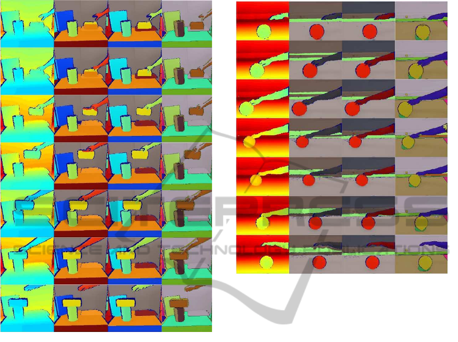
As an example of a typical manipulation action,
we show segmentation results for a human hand
grasping a carton box and placing it on top of a cylin-
drically shaped paper roll (see Fig. 2). In Fig. 2(a),
selected calibrated depth images acquired with the
Kinect are shown. In Fig. 2(b), the segmentation re-
sults obtained by our method are shown. Fig. 2(c)
shows a ground truth segmentation of surfaces as per-
ceived by a human for comparison. Fig. 2(d) shows
results obtained using video-segmentation algorithm
based on color for comparison (Grundmann et al.,
2010). The segments are color-coded, where each
color corresponds to a unique segment label. With
our method not all surfaces could be completely re-
covered in the initial segmentation, due to the lim-
ited depth resolution. However, in the following, a
change of position of the carton box allows correctly
JointSegmentationandTrackingofObjectSurfacesinDepthMoviesalongHuman/RobotManipulations
247
(a)
(b)
(c) (d)
Figure 2: Hand grasping a carton box. (a) Depth image
(Kinect). (b) Video segmentation results using our method.
(c) Human segmentation used as ground-truth (d) Color im-
age video segmentation using (Grundmann et al., 2010).
segmenting and tracking the surfaces (see Fig. 2(b)).
In comparison with the ground truth (Fig. 2(c)), it
can be seen that a small percent of false label assign-
ments happens during the manipulation of the carton
box, since local depth information becomes insuffi-
cient. The problem is resolved to a certain degree by
regrouping (see step (7) of the algorithm). In compar-
ison, in the color-based approach (shown in Fig. 2(d)),
the hand is merged with both the background and the
carton box. This is an inherent problem in algorithms
which rely on color information alone, because dif-
ferent surfaces cannot be guaranteed to always have a
different color.
Next, we present results for a human hand rolling
a green ball forward and then backwards with its fin-
gers (see Fig. 3). The ball and the hand are correctly
segmented and tracked along the image sequence,
even though the hand is changing its shape during the
motion (see Fig. 3 (b)). Ground-truth segmentations
and the results of the color-based video segmentation
(a)
(b)
(c) (d)
Figure 3: Hand rolling a ball. (a) Depth image (Kinect). (b)
Video segmentation results using our method. (c) Human
segmentation used as ground-truth (d) Color video segmen-
tation using (Grundmann et al., 2010).
proposed by Grundmann et al. (2010) are shown for
comparison in Fig. 3(c-d), respectively.
We further show segmentation results for a movie
where a robot arm grasps a cylindrically-shaped paper
roll and moves it to a new position (see Fig. 4). Dur-
ing the movement, objects in the background become
occluded. Nevertheless, the sequence is correctly seg-
mented and both the robot arm and the paper roll are
tracked along the movie, as can be seen in Fig. 4(b).
In the color-based video segmentation (see Fig. 4(d)),
the robot arm gets over segmented and the carton box,
which is lying on the table, gets merged with the table
(undersegmented).
Finally, we demonstrate a scenario in which mul-
tiple segments are tracked simultaneously. Fig. 5
shows selected frames of a plant movie. It can be
seen that as the plant is being displaced, multiple seg-
ments are tracked jointly through the scene. Notice
that two leaves in the initial segmentation were un-
der segmented so they are tracked in the same way in
upcoming frames.
5.2 Quantitative Evaluation
We use the segmentation covering metric described
VISAPP2013-InternationalConferenceonComputerVisionTheoryandApplications
248
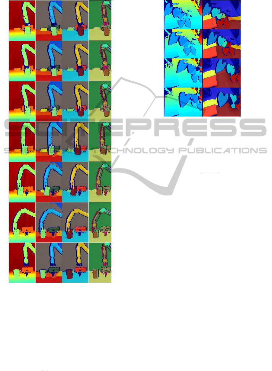
(a)
(b)
(c) (d)
Figure 4: WAM robotic arm grasping and displacing a pa-
per roll. (a) Depth image (Kinect). (b) Video segmentation
results using our method. (c) Human segmentation used as
ground-truth (d) Color video segmentation using (Grund-
mann et al., 2010).
in Arbelaez et al. (2009) to determine how closely the
segmentation results match the ground truth segmen-
tation. Human annotated color images are used as
ground truth (column (c) of Fig. 2, 3, 4). For one
frame, the segmentation covering metric is defined as
C(S
0
→S) =
1
N
∑
R∈S
|R|·max
R
0
∈S
0
O
R,R
0
(7)
(a)
(b)
Figure 5: Plant being displaced. (a) Depth image (Kinect).
(b) Video segmentation results using our method.
where N is the total number of pixels in the image, |R|
the number of pixels in the region R, and O(R,R
0
) is
the overlap between the regions R and R
0
defined as
O(R,R
0
) =
|R ∩ R
0
|
|R ∪ R
0
|
(8)
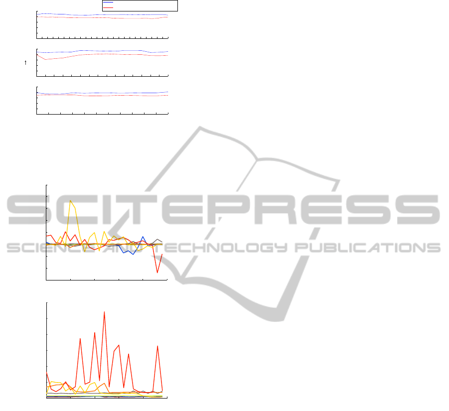
Fig. 6 (blue line) shows a plot of the segmenta-
tion covering metric for the segmentation results of
our algorithm, corresponding to videos of Fig. 2, 3, 4.
The segmentation covering metric is computed for
frames taken at fixed time intervals. The segmenta-
tion covering metric of the segmentation result shown
in Fig. 6(c,blue line) has a lower value compared to
the other examples because in this case the back-
ground got over-segmented initially and the algo-
rithm tries to track these over-segmented surfaces
in upcoming frames, as can be seen in Fig. 4(b).
We also plotted the segmentation covering metric for
the color-video-segmentation results obtained with a
graph-based video segmentation algorithm (Grund-
mann et al., 2010) in red for comparison. For the
given set of movies, our method clearly outperforms
the method described in (Grundmann et al., 2010).
For the plant movie (Fig. 5) similar results were ob-
tained. The segmentation covering metric gave a
value of 0.89 and 0.83 for the initial and the final
frame, respectively, when compared to a human per-
ceived segmentation.
We evaluated the coherence of the segmentations
by measuring the segment size ratio 4a
i
of the seg-
ments s
i
as a function of time. For the example of
Fig. 2, results are shown in Fig. 7(a). The line-plot
colors correspond to the label colors used in Fig. 2(b).
The segment size ratios are fluctuating between 0.8
JointSegmentationandTrackingofObjectSurfacesinDepthMoviesalongHuman/RobotManipulations
249
0 1 2 3 4 5 6 7 8 9 10 11 12 13 14 15 16 17 18 19 20 21 22 23 24
0
0.2
0.4
0.6
0.8
1
Our segmentation algorithm
Color segmentation
0 10 20 30 40 50 60 70 80 90 100 110 120 130 140 150
0
0.2
0.4
0.6
0.8
1
0 5 10 15 20 25 30 35 40 45 50 55
0
0.2
0.4
0.6
0.8
1
iterations
C(S' S)
(b)
(a)
(c)
Figure 6: Segmentation covering metric for the results ob-
tained with our segmentation algorithm (in blue) and with
the graph-based method (Grundmann et al., 2010) (in red)
for the scenes shown in (a) Fig. 2, (b) Fig. 3 and (c) Fig. 4.
0 5 10 15 20 25
0
0.02
0.04
0.06
0.08
0.1
0.12
(b)
0 5 10 15 20 25
0.4
0.6
0.8
1
1.2
1.4
1.6
1.8
2
Segment size ratio
Frames [t]
(a)
Average surface model fitting error [meters]
Frames [t]
Figure 7: Evaluation of segmentation coherence and surface
fitting error. (a) Segment size ratio 4a
i
as a function of the
frame number for all segments s
i
shown in Fig. 2. (b) Sur-
face fitting errors E
i
as a function of the frame number. Line
colors correspond to the segment-label colors of Fig. 2(c).
and 1.2, indicating that temporal consistency is main-
tained.
We further compared the depth predicted by the
surface models of the segments with the measured
(ground truth) depth and computed the fitting error for
each segment (see Fig. 7(b)). Except for the hand, the
fitting error remains below 0.02 meters. The larger
errors measured for the hand are caused by small seg-
mentation errors at its large boundary lines due to its
fast motion, which affects the tracking procedure neg-
atively.
5.3 Parameter Choices
The algorithm contains two important parameters,
i.e., ρ and δ, which may require tuning. The remain-
ing parameters r
1
and r
2
are less critical.
For our set-up, the parameter ρ required for the
segmentation of consecutive frames was determined
only once and not altered during the different experi-
ments, except for one experiment, for which it needed
to be increased. With our chosen value of ρ = 1.7, an
average of 74% of points per segment served as seed
points.
By evaluating the segment-size ratio over time
(see Fig. 7(a)), which, in case of successful track-
ing, stayed in between 0.8 and 1.2, we set parameter
δ equal to 0.2, providing a reasonable bound on the
segment-size change of 20%. This parameter, once
set, was not varied throughout the experiments. The
remaining parameters were set to r
1
= 10 pixels and
r
2
= 15 pixels.
6 CONCLUSIONS
We presented a novel algorithm for joint segmentation
and tracking of object surfaces, defined by their geo-
metric shapes. Segments obtained for the first frame
are used to initialize the segmentation procedure of
the next frame, and so on. The main novelties of
the proposed method are (i) the use quadratic surface
models for seeding and in the context of a tracking
problem (steps 2-3), (ii) a labeling technique for non-
seed points, defined by Eq. 6 (see step 6 of the algo-
rithm), and a re-grouping strategy enforcing temporal
consistency between frames (step 7). We tested the al-
gorithm for several movies acquired with the Kinect
showing human and robot manipulations of objects.
The algorithm allowed us to segment and track the
main object surfaces in the scene, despite frequently
occurring occlusions, limited resolution of the depth
images, and shape changes of the hand and the robot
gripper. However, some problems still remain. Oc-
casionally, depth differences between surfaces are too
small, resulting in assignment conflicts that cannot be
resolved by the method as it is. In the future, we aim
to incorporate additional mechanisms for improving
the robustness of the method in this respect. Further-
more, we are currently developing mechanisms for
generating new segments in addition to the ones that
have been determined in the first frame, which will be
important in case new objects are entering the scene.
This will also allow segmenting images from scratch
in the future, i.e., the initial frame. The segment con-
sistency check and the following re-grouping proce-
VISAPP2013-InternationalConferenceonComputerVisionTheoryandApplications
250

dure are currently conducted using hard thresholds,
which we plan to make adaptive in the future. We plan
to make our tracking algorithm more robust to occlu-
sions and noise by using shape information from all
the previous time steps. A way to achieve this would
be building dynamic shape models (Cremers, 2006).
We provided a quantitative evaluation of the
method using human-annotated ground truth. Obtain-
ing ground-truth for video is however a very tedious
procedure and thus poses us limits. Since there is
no implementation of a similar algorithm performing
joint segmentation and tracking in depth space avail-
able, we compared our method to a standard color-
video segmentation algorithm (Grundmann et al.,
2010). We could show that our method outperformed
color-video segmentation for the videos analyzed.
However, this comparison may not be entirely fair,
since we are using a different feature, i.e., depth, and
not color.
Currently, the method needs ∼ 1.92 seconds to
process one frame of size 430 × 282 pixels in Matlab
on Intel 3.3 GHz processor. With an efficient C/C++
implementation of the method, we expect to gain real-
time performance, which is one of our next goals.
ACKNOWLEDGEMENTS
This research is partially funded by the EU
projects GARNICS (FP7-247947) and IntellAct
(FP7-269959), and the Grup consolidat 2009
SGR155. B. Dellen acknowledges support from the
Spanish Ministry of Science and Innovation through
a Ramon y Cajal program.
REFERENCES
Abramov, A., Aksoy, E. E., D
¨
orr, J., W
¨
org
¨
otter, F., Pauwels,
K., and Dellen, B. (2010). 3d semantic representation of
actions from efficient stereo-image-sequence segmenta-
tion on gpus. In 5th Intl. Symp. 3D Data Processing,
Visualization and Transmission.
Agostini, A., Torras, C., and W
¨
org
¨
otter, F. (2011). Inte-
grating task planning and interactive learning for robots
to work in human environments. In IJCAI, Barcelona,
pages 2386–2391.
Aksoy, E. E., Abramov, A., D
¨
orr, J., Ning, K., Dellen, B.,
and W
¨
org
¨
otter, F. (2011). Learning the semantics of
object-action relations by observation. Int. J. Rob. Res.,
30(10):1229–1249.
Arbelaez, P., Maire, M., Fowlkes, C., and Malik, J. (2009).
From contours to regions: An empirical evaluation. In
CVPR, pages 2294 –2301.
Cremers, D. (2006). Dynamical statistical shape priors for
level set-based tracking. IEEE TPAMI, 28(8):1262 –
1273.
Dellen, B., Alenya, G., Foix, S., and Torras, C. (2011). Seg-
menting color images into surface patches by exploiting
sparse depth data. In IEEE Workshop on Applications of
Computer Vision, pages 591 –598.
Deng, Y. and Manjunath, B. (2001). Unsupervised segmen-
tation of color-texture regions in images and video. IEEE
TPAMI, 23(8):800 –810.
Felzenszwalb, P. F. and Huttenlocher, D. P. (2004). Efficient
graph-based image segmentation. Intl. J. of Computer
Vision, 59(2):167–181.
Grundmann, M., Kwatra, V., Han, M., and Essa, I. (2010).
Efficient hierarchical graph-based video segmentation.
In CVPR, pages 2141 –2148.
Hofman, I. and Jarvis, R. (2000). Object recognition via
attributed graph matching. In Proc. Australian Conf. on
Robotics and Automation, Melbourne, Australia.
Kinect (2010). Kinect for xbox 360. In http://
www.xbox.com/en-US/kinect.
Kragic, D. (2001). Visual Servoing for Manipulation: Ro-
bustness and Integration Issues. PhD thesis, Computa-
tional Vision and Active Perception Laboratory, Royal
Institute of Technology, Stockholm, Sweden.
Kruskal, J. B. (1956). On the Shortest Spanning Subtree of
a Graph and the Traveling Salesman Problem. In Proc.
of the American Mathematical Society.
Lopez-Mendez, A., Alcoverro, M., Pardas, M., and Casas,
J. (2011). Real-time upper body tracking with online ini-
tialization using a range sensor. In IEEE Intl. Conf. on
Computer Vision Workshops, pages 391 –398.
Parvizi, E. and Wu, Q. (2008). Multiple object tracking
based on adaptive depth segmentation. In Canadian
Conf. on Computer and Robot Vision, pages 273 –277.
Patras, I., Hendriks, E., and Lagendijk, R. (2001). Video
segmentation by map labeling of watershed segments.
IEEE TPAMI, 23(3):326 –332.
Rozo, L., Jimenez, P., and Torras, C. (2011). Robot learn-
ing from demonstration of force-based tasks with multi-
ple solution trajectories. In 15th Intl. Conf. on Advanced
Robotics, pages 124 –129.
Taylor, G. and Kleeman, L. (2002). Grasping unknown ob-
jects with a humanoid robot. In Proc. of Australasian
Conf. on Robotics and Automation, pages 191–196.
Wang, C., de La Gorce, M., and Paragios, N. (2009).
Segmentation, ordering and multi-object tracking using
graphical models. In IEEE 12th Intl. Conf. on Computer
Vision, pages 747 –754.
Wang, D. (1998). Unsupervised video segmentation based
on watersheds and temporal tracking. IEEE Transactions
on Circuits and Systems for Video Technology, 8(5):539
–546.
JointSegmentationandTrackingofObjectSurfacesinDepthMoviesalongHuman/RobotManipulations
251
