
3D Reconstruction of Interreflection-affected Surface Concavities using
Photometric Stereo
Steffen Herbort, Daniel Schugk and Christian Wöhler
Image Analysis Group, TU Dortmund, Otto-Hahn-Straße 4, 44227 Dortmund, Germany
Keywords:
3D surface Reconstruction, Photometric Stereo, Interreflections, Surface Concavities.
Abstract:
Image-based reconstruction of 3D shapes is inherently biased under the occurrence of interreflections, since the
observed intensity at surface concavities consists of direct and global illumination components. This issue is
commonly not considered in a Photometric Stereo (PS) framework. Under the usual assumption of only direct
reflections, this corrupts the normal estimation process in concave regions and thus leads to inaccurate results.
For this reason, global illumination effects need to be considered for the correct reconstruction of surfaces
affected by interreflections. While there is ongoing research in the field of inverse lighting (i.e. separation
of global and direct illumination components), the interreflection aspect remains oftentimes neglected in the
field of 3D shape reconstruction. In this study, we present a computationally driven approach for iteratively
solving that problem. Initially, we introduce a photometric stereo approach that roughly reconstructs a surface
with at first unknown reflectance properties. Then, we show that the initial surface reconstruction result can
be refined iteratively regarding non-distant light sources and, especially, interreflections. The benefit for the
reconstruction accuracy is evaluated on real Lambertian surfaces using laser range scanner data as ground
truth.
1 INTRODUCTION
The problem of image-based shape reconstruction has
been examined by Horn (Horn, 1970) using a single
image and regularization constraints for “Shape from
Shading (SfS)". The Photometric Stereo (PS) princi-
ple evolved later on (Woodham, 1980), favorably re-
moving the constraints, but needing at least three in-
tensity measurements per pixel obtained under vary-
ing illumination directions. Both, the SfS and the PS
setup, assume distant light sources with known illu-
mination direction and intensity, which is nowadays
termed “calibrated Photometric Stereo". Addition-
ally, the observed surfaces are assumed to be strictly
Lambertian (Lambert, 1760).
The case of uncalibrated PS has been examined
extensively, starting with Hayakawa’s seminal work
(Hayakawa, 1994), where the problem of an ambigu-
ity in the determinable light source position from PS
image data becomes exposed. That “Generalized Bas-
Relief (GBR) ambiguity" (Belhumeur et al., 1999)
was subject to extensive research and has been solved
using e.g. the generic viewpoint constraint (Freeman,
1994; Yuille et al., 2000), minimization of the surface
albedo distribution entropy (Alldrin et al., 2007), by
modeling the illumination conditions using spherical
harmonics (Basri et al., 2007), or with special relative
light source arrangements (Zhou and Tan, 2010).
In parallel, non-Lambertian surfaces have been
approached by different authors. (Ikeuchi, 1981)
assume purely specular surfaces, (Nayar et al.,
1988; Nayar et al., 1990a) assume hybrid sur-
faces with Lambertian and superimposed specu-
lar components. For these methods, the im-
age formation and object reflection properties be-
come relevant. Well-known reflectance function
models are e.g. Lambert (Lambert, 1760), Oren-
Nayar (Oren and Nayar, 1994), Blinn (Blinn,
1977), Phong (Phong, 1975), Lafortune (Lafortune
et al., 1997), Beckmann-Spizzichino (Beckmann and
Spizzichino, 1987), Torrance-Sparrow (Torrance and
Sparrow, 1967), Ward (Ward, 1992), Ward-Dür-
Geisler-Moroder (Geisler-Moroder and Dür, 2010).
Since PS works robustly on Lambertian surfaces,
there has been research regarding the separation of
diffuse and specular components, which then al-
lows performing PS on the diffuse component only.
These use e.g. polarization (Wolff, 1989; Wolff and
Boult, 1991), color (Tan and Ikeuchi, 2005; Thomas
and Sugimoto, 2010), or both (Nayar et al., 1997).
208
Herbort S., Schugk D. and Wöhler C..
3D Reconstruction of Interreflection-affected Surface Concavities using Photometric Stereo.
DOI: 10.5220/0004213702080214
In Proceedings of the International Conference on Computer Vision Theory and Applications (VISAPP-2013), pages 208-214
ISBN: 978-989-8565-48-8
Copyright
c
2013 SCITEPRESS (Science and Technology Publications, Lda.)

The model-based reflectance description has been re-
laxed by BRDF
1
-independent approaches like (Zick-
ler et al., 2002; Alldrin et al., 2008).
A new formulation of the problem using a projec-
tive framework has been published by (Tan and Zick-
ler, 2009; Tankus et al., 2005). Further variations of
the PS framework regard e.g. exploiting the effects of
non-distant light sources (Iwahori et al., 1990; Clark,
1992).
PS itself determines only pixelwise surface nor-
mals or gradients, while absolute depth determination
requires a postprocessing step, which was elaborately
examined by (Agrawal et al., 2006).
Due to the common assumption of single sur-
face reflections (direct illumination) and disregarding
higher orders (interreflections, a subset of global il-
lumination), it is not possible to infer the underly-
ing surface normal from the observed intensity cor-
rectly. Fig. 1 depicts an image separated into direct
and global illumination components and illustrates
the intensity aggregation in concavities.
0
20
40
60
80
100
120
140
160
180
(a) camera image
0
20
40
60
80
100
120
140
160
180
(b) direct component
0
20
40
60
80
100
120
140
160
180
(c) global component
Figure 1: Measured illumination components of a camera
image using the method by (Seitz et al., 2005) for (b) and
a variant of that method with an inverse illumination pat-
tern for (c). Note that all images have the same grayvalue
scaling.
Systems for synthetically computing global illu-
mination exist in a large variety. One of the open
source ray tracers that additionally employs physi-
cally plausible BRDFs, which is crucial for correct
1
Bidirectional Reflectance Distribution Function
real world object representation, is PBRT
2
(Pharr and
Humphreys, 2010).
While extensive research has been carried out re-
garding (non-) Lambertian surfaces and uncalibrated
PS, there is hardly any research regarding the image-
based reconstruction of 3D shapes in the presence of
interreflections. Basic thoughts have been published
by (Nayar et al., 1990b) who iteratively refine concave
v-shapes. The case of inversely computing global
illumination with (at most) second order reflections
along its path has been examined by (Yu et al., 1999),
who use their data for realistic scene modeling and
relighting. The effect of interreflections and the re-
sulting inaccuracies on structured light laser scanning
profiles have been discussed by (Gupta et al., 2011)
and (Couture et al., 2011), but photometric aspects
remain untreated therein.
The work by (Gu et al., 2011) stresses the influ-
ence of interreflections for PS. Their method is based
on multiplexed illumination (Nayar et al., 2006) for
the separation of global and direct illumination in the
image acquisition stage. They apply high frequency
patterns under different incident directions for esti-
mating the two scene illumination components. The
direct component is then used to estimate shapes with
strongly increased accuracy using PS.
To the authors’ best knowledge, there is no publi-
cation that actually deals with a method for the recon-
struction of shapes with interreflection-affected con-
cavities under illumination with simple point light
sources (LEDs).
2 CONSIDERATION OF
INTERREFLECTIONS
We propose a novel method that accounts for inter-
reflections in a fully calibrated photometric stereo en-
vironment. The approach as such imposes no restric-
tions upon their reflective behavior and thus allows
arbitrary and possibly even measured BRDFs. Fur-
thermore, the light sources are not assumed to be dis-
tant, which is not a prerequisite for our algorithm
to work but it improves the reconstruction accuracy.
Calibration of the (point) light source positions and
intensities is achieved using the method described by
(Lenoch et al., 2012). Absolute surface depth data
is computed using Agrawal’s M-estimator approach
(Agrawal et al., 2006). In the following, the con-
catenation of PS and Agrawal’s method is denoted
“PS+Z".
Our key to the consideration of interreflections lies
2
Physically Based Ray-Tracer v2, pbrt.org
3DReconstructionofInterreflection-affectedSurfaceConcavitiesusingPhotometricStereo
209

PS+Z w/ Lambert and
global light directions
images
images
images
images
scene
configuration
PS+Z w/ Lambert and
local light directions
remove
interreflections
PS+Z w/
local light directions
final surface
PS+Z w/ BRDF and
local light directions
estimate BRDF
Figure 2: Algorithm overview. “PS+Z" denotes photomet-
ric normal estimation and followed by depth integration.
Note that each group of components (green, orange, blue)
can possibly be iterated.
in an iterative scheme: (1) Our method initially recon-
structs the surface based on distant light sources and
Lambertian reflectance. (2) That result becomes re-
fined assuming non-distant light sources. The result-
ing surface is afterwards used (3) to obtain the param-
eters of a parametric BRDF, which additionally re-
fines the surface in another reconstruction step. Lastly
(4), the consideration of interreflections is incorpo-
rated by determination of the amount of global illu-
mination with a physically plausible rendering sys-
tem. This allows us to remove a (significant) amount
of interreflection-based radiance from the captured
scene image data and thus to obtain a refined recon-
struction result. Note that it may be beneficial to re-
peat some of the stages described above in order to
ensure their convergence. Fig. 2 gives an overview of
these elements.
We demonstrate the potential of our method on
real data for a Lambertian and a non-Lambertian sur-
face. The validation of the correctness of these results
is achieved on the one hand by comparison with the
surface data measured by an industry-standard laser
scanner and on the other hand based on synthetically
rendered images with a known underlying surface.
In contrast to related publications, we model point
light sources and are thus not required to illuminate
the scene with specialized projectors like (Gu et al.,
2011); furthermore, there is no shape restriction like
the v-shapes examined by (Nayar et al., 1990b).
3 ALGORITHM DETAILS
In stage 1 (yellow), the surface normals are computed
for each pixel (u, v) based on the standard PS equation
for Lambertian surfaces,
~
I
obs
(u,v) = I
0
ρ(u,v) L ~n(u,v), (1)
where u and v denote the pixel indices,
~
I
obs
(u,v) ∈
R
k×1
denotes the vector of k observed intensity sam-
ples under i = 1...k varying (distant) normalized il-
lumination directions
~
l
i
with |
~
l
i
|
2
= 1. The light
source relative radiance is referred to as I
0
and the
light source directions are aligned row-wise in L =
[l
1x
,l
1y
,l
1z
;l
2x
,l
2y
,l
2z
;...]. The surface normals are
~n = [n
x
,n
y
,n
z
]
T
with |~n|
2
= 1 and ρ denotes the sur-
face albedo. The surface normal is thus determined in
the least-mean-square (LMS) sense using
~n(u,v) =
1
I
0
ρ(u,v)
L
−1
~
I
obs
(u,v) (2)
with a pseudo-inverse L
−1
. Note, that locally varying
albedos can be obtained when solving for~n and ρ with
known irradiance I
0
:
~n
∗
= L
−1
~
I
obs
(u,v), I
0
ρ = |~n
∗
|
2
, ~n =
~n
∗
|~n
∗
|
2
(3)
The obtained surface normal field is then integrated to
absolute depth values using the M-estimator approach
described by (Agrawal et al., 2006). For the trans-
formation into a metric depth space, the algorithm is
given the approximate object distance from the cam-
era, which suffices for the determination of pixel ex-
tents and thus metric depth scaling.
In stage 2 (green), the light sources are regarded as
non-distant. This alters the image intensity equation
such that
~
I
obs
(u,v) =
I
0
ρ
r
2
1
(u,v) r
2
2
(u,v)
L(u,v) ~n. (4)
Note that we assume locally varying illumination di-
rections
~
l
i
(u,v) for each pixel (u, v) and each light
source i = 1...k, which is due to the scene being il-
luminated by non-distant point light sources. Addi-
tionally, each pixel is assigned the light travel dis-
tance from the light source to the object (r
1
) and
from the object to the camera sensor (r
2
). Even on
this small-scaled framework (object height ≈ 50mm,
mean(r
1
) ≈ 300mm and mean(r
2
) ≈ 310mm), this
shows a significant effect. Up to this point, the sur-
face has been assumed to be perfectly Lambertian and
VISAPP2013-InternationalConferenceonComputerVisionTheoryandApplications
210

free of global illumination.
In stage 3 (orange), the BRDF of the underlying ma-
terial is estimated globally based on the extracted sur-
face from stage 2 and the obtained images. This
is achieved by minimizing the RMSE of the inten-
sity data I = I(u,v) and the rendered intensities R =
R(
~
P,u, v) of the surface with respect to the parameter
~
P of the chosen BRDF:
~
P
opt
= argmin
~
P
s
1
U ·V
U
∑
u=1
V
∑
v=1
[I − R]
2
. (5)
For Lambertian surfaces, the only parameter is the
surface albedo ρ, which can be computed by deter-
mination of I
0
using (Lenoch et al., 2012) and thus
having white balance data available.
In stage 4 (blue), the interreflection component is (it-
eratively) compensated before starting the PS+Z algo-
rithm: Two separate images of the last stage’s PS+Z
surface result are rendered under (1) direct R
d,i
and (2)
global R
g,i
illumination for each light source i = 1...k.
Afterwards, the global component is determined as
the difference between R
g,i
and R
d,i
, which is used to
compensate these in the real camera images I
i
:
I
new,i
= I
i
− (R
g,i
− R
d,i
)
| {z }
interreflections
i = 1...k (6)
As a last step for this stage, the PS+Z algorithm is
started on the new image data basis I
new,i
.
4 EXPERIMENTS AND RESULTS
Figure 3 gives an overview of the setup used for data
acquisition. Due to using the same camera for im-
age acquisition and ground truth depth measurement
(structured light laser scanning system), it is possible
to capture pixel synchronous depth and image data,
which facilitates the evaluation process significantly.
The description and discussion of our experiments is
structured as follows: Initially, we analyze the pro-
gressing change in PS+Z depth with increasing al-
gorithm iterations (Sec. 4.1). Afterwards (Sec. 4.2),
we show the beneficial effect of our approach quali-
tatively based on an analysis of the reflectance maps
with global illumination.
Sec. 4.3 then shows the comparison of the PS+Z
depth result with independently measured scanner
depth data z
RS
for a region of the surface that is es-
pecially affected by interreflections. To conclude the
evaluation, the aspect of algorithm convergence is dis-
cussed in Sec. 4.4 along with suitable criteria that ter-
minate the execution at a reasonable state.
Figure 3: Overview of the experimental setup. The object
has a height of about 50 mm, the distance between object
and camera (2) / object and illumination (3) amounts to ap-
proximately 250 mm. Note that the laser range scanner (1)
is used for validation only.
4.1 Progressing Change in
Reconstructed Depth
Fig. 4 shows the differences between the naive PS+Z
depth z
PS,1
(no interreflection compensation) and its
iterations z
PS,2...5
using image data with compensated
interreflections. It becomes clear that the compen-
sation of the global (interreflection) component pro-
duces deeper concavities compared to the uncompen-
sated case. The results show that less deep concav-
(a) z
PS,2
− z
PS,1
(b) z
PS,3
− z
PS,1
(c) z
PS,4
− z
PS,1
(d) z
PS,5
− z
PS,1
Figure 4: Difference between the naive PS depth z
PS,1
(no
interreflection compensation) and the iterations using im-
age data with compensated interreflections z
PS,2...5
. Scale:
−0.5mm (dark blue) to 2.5 mm (red).
ities on the one hand (e.g. neck and ear region) ex-
hibit only a change in depth over the early iterations
3DReconstructionofInterreflection-affectedSurfaceConcavitiesusingPhotometricStereo
211
of the algorithm, but remain static on the late itera-
tions. Deep concavities on the other hand progress in
their depth over several iterations. This already gives
a hint that the algorithm converges suitably, since re-
gions with shallow and deeper concavities converge
independently.
4.2 Qualitative Evaluation
Fig. 5 shows reflectance maps from different stages
of the algorithm. Note that at iteration 5 (Fig. 5(c)),
the object surface appears more similar to the physi-
cal image (Fig. 5(a)), especially in the interreflection-
affected regions. For a human observer, it is obvious
(a) image
(b) stage 4, iteration 1 rendering re-
sult (global illumination)
(c) stage 4, iteration 5 rendering re-
sult (global illumination)
Figure 5: Rendered PS+Z results. Note the appearance dif-
ference at surface concavities.
that the underlying surface resembles the one of the
physical image more closely due to the perceived in-
tensities and due to the plausibility of where and how
shadows are cast. In summary, the qualitative assess-
ment result of the surface is very favorable, due to fine
surface details being visible and surface concavities
being shaped as expected from the real world object
image.
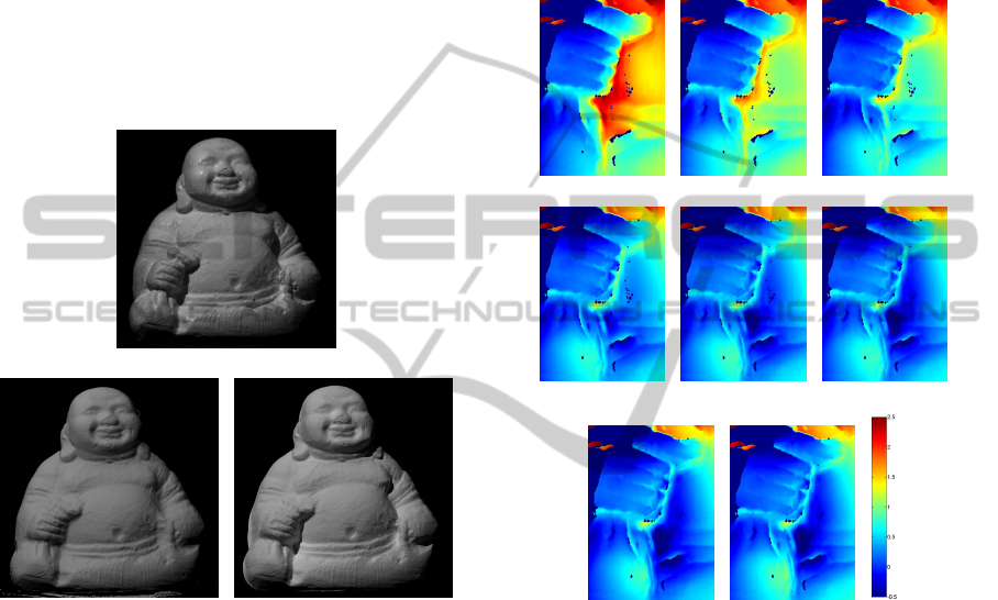
4.3 Quantitative Evaluation
Fig. 6 shows a comparison of the reconstructed depth
z
PS,n
and quantitatively measured depth data obtained
using a laser range scanner z
RS
for the iterations
n = 1...8. The registration of both (already pixelsyn-
chronous) depth profiles has been achieved by align-
ing the absolute depth of a convex surface part in
the “hand"-region. This ensures that the PS+Z depth
z
PS,n
is unaffected by interreflections in that area, and
thus allows unbiased registration. With naive photo-
metric reconstruction (no compensation of interreflec-
tions, z
PS,1
, Fig. 6(a)), there are very strong differ-
ences visible between the reconstructed surface z
PS,1
and the ground truth scanner depth z
RS
, which are in
the range of some mm. The differences initially reach
(a) z
RS
− z
PS,1
(b) z
RS
− z
PS,2
(c) z
RS
− z
PS,3
(d) z
RS
− z
PS,4
(e) z
RS
− z
PS,5
(f) z
RS
− z
PS,6
(g) z
RS
− z
PS,7
(h) z
RS
− z
PS,8
(i)
scale
Figure 6: Ground truth validation. Scale: −0.5 mm (dark
blue) to 2.5mm (red).
more than 2 mm (Fig. 6(a)), which is unacceptable in
terms of measurement accuracy for e.g. industrial ap-
plications. Tn the course of the iterations, the differ-
ences decrease quickly and already after the second
iteration with interreflection-compensated image data
(z
PS,3
, Fig. 6(c)), the error has decreased over a wide
range of the concavity.
4.4 Convergence Criterion
Although it seems to be of less importance when to
stop iterating due to e.g. shallow concavities remain-
ing unchanged while deeper concavities still deepen,
it makes sense to include another criterion for robust-
ness and for saving computational time. We found
it particularly useful to examine the mean absolute
VISAPP2013-InternationalConferenceonComputerVisionTheoryandApplications
212

1 2 3 4 5 6 7
0
0.1
0.2
0.3
0.4
0.5
0.6
iteration
mean absolute depth difference
Figure 7: Average change in depth ∆z
n
= mean(|z
PS,n
−
z
PS,1
|) per iteration in the “bag"-section.
change in depth of the photometrically reconstructed
depth data of iteration n (i.e. z
PS,n
) compared to the
initial PS+Z result without compensation of inter-
reflections (i.e. z
PS,1
) such that ∆z
n
= mean(|z
PS,n
−
z
PS,1
|). Once that change is lower than a certain
threshold (here: ∆z
n
< 0.02mm), the computation is
regarded as complete. In our case, convergence is
then reached after the 4
th
iteration.
5 SUMMARY
AND CONCLUSIONS
We have presented a novel, iterative approach for
dealing with interreflections in the context of PS
based shape reconstruction. The algorithm initially
reconstructs the depth profile without consideration of
interreflections using a PS approach and subsequent
absolute depth estimation based on the PS gradient
fields. Since that profile mainly bares errors in re-
gions affected by excessive light emission due to in-
terreflections, we have introduced an iterative scheme
that computes the intensity of the global illumination
at surface concavities and then removed these from
the physical image data before using that improved
data for PS and absolute depth reconstruction.
The evaluation showed a qualitatively and quan-
titatively beneficial effect for the extracted surface.
The results show furthermore, that convergence is
reached already after ≈ 4 iterations (for the given sur-
face). Furthermore, a criterion (mean absolute depth
change) has been presented that allows to determine
when the computation has finished.
In future work, there is mainly the need to perform
experiments with non Lambertian surfaces, which are
significantly more common in the real world than the
applied Lambertian surfaces. Conceptually, this re-
quires the algorithm to handle the BRDF estimation
and absolute depth estimation step with greater ro-
bustness, but the basic functionality and algorithm
principle will remain unchanged.
REFERENCES
Agrawal, A., Raskar, R., and Chellappa, R. (2006). What
is the range of surface reconstructions from a gradient
field? Proceedings of the European Conference on
Computer Vision (ECCV 2006), 1(TR2006-021):578–
591.
Alldrin, N., Zickler, T., and Kriegman, D. (2008). Pho-
tometric stereo with non-parametric and spatially-
varying reflectance. 2008 Conference on Computer
Vision and Pattern Recognition (CVPR2008).
Alldrin, N. G., Mallick, S. P., and Kriegman, D. J. (2007).
Resolving the generalized bas-relief ambiguity by en-
tropy minimization. 2007 Conference on Computer
Vision and Pattern Recognition (CVPR).
Basri, R., Jacobs, D. W., and Kemelmacher, I. (2007).
Photometric stereo with general, unknown lighting.
International Journal of Computer Vision (IJCV),
72(3):239–257.
Beckmann, P. and Spizzichino, A. (1987). The Scattering of
Electromagnetic Waves from Rough Surfaces. Num-
ber ISBN-13: 987-0890062382. Artech House Radar
Library.
Belhumeur, P. N., Kriegman, D. J., and Yuille, A. L. (1999).
The bas-relief ambiguity. International Journal of
Computer Vision (IJCV), 35(1):1040–1046.
Blinn, J. F. (1977). Models of light reflection for com-
puter synthesized pictures. ACM SIGGRAPH Com-
puter Graphics, 11(2):192–198.
Clark, J. J. (1992). Active photometric stereo. Proceedings
of the 1992 IEEE Computer Society Conference on
Computer Vision and Pattern Recognition (CVPR’92),
pages 29–34.
Couture, V., Martin, N., and Roy, S. (2011). Unstruc-
tured light scanning to overcome interreflections.
ICCV’2011, pages 1–8.
Freeman, W. T. (1994). The generic viewpoint assump-
tion in a framework for visual perception. Nature,
368:542–545.
Geisler-Moroder, D. and Dür, A. (2010). A new ward brdf
model with bounded albedo. Eurographics Sympo-
sium on Rendering 2010, 29:1391–1398.
Gu, J., Kobayashi, T., Gupta, M., and Nayar, S. K. (2011).
Multiplexed illumination for scene recovery in the
presence of global illumination. ICCV 2011, pages
1–8.
Gupta, M., Agrawal, A., Veeraraghavan, A., and
Narasimhan, S. G. (2011). A practical approach to
3d scanning in the presence of interreflections, subsur-
face scattering and defocus. CVPR’2011, IJCV’2012,
pages 1–24.
Hayakawa, H. (1994). Photometric stereo under a light
source with arbitrary motion. Journal of Optical So-
ciety of America A (JOSA A), 11:3079–3089.
3DReconstructionofInterreflection-affectedSurfaceConcavitiesusingPhotometricStereo
213

Horn, B. K. P. (1970). Shape from shading: A method for
obtaining the shape of a smooth opaque object from
one view. Technical Report 232, Messachusets Insti-
tute of Technology.
Ikeuchi, K. (1981). Determining surface orientations of
specular surfaces by using the photometric stereo
method. IEEE Transactions on Pattern Analysis and
Machine Intelligence, 3(6):661–669.
Iwahori, Y., Sugie, H., and Ishii, N. (1990). Reconstructing
shape from shading images under point light source
illumination. Proceedings of IEEE 10th International
Conference on Pattern Recognition (ICPR’90), 1:83–
87.
Lafortune, E. P. F., Foo, S.-C., Torrance, K. E., and Green-
berg, D. P. (1997). Non-linear approximation of re-
flectance functions. SIGGRAPH’97, pages 117–126.
Lambert, J.-H. (1760). Photometria, sive de mensura et
gradibus luminis, colorum et umbrae. Vidae Eber-
hardi Klett.
Lenoch, M., Herbort, S., and Wöhler, C. (2012). Robust and
accurate light source calibration using a diffuse spher-
ical calibration object. Oldenburger 3D Tage 2012,
11:1–8.
Nayar, S. K., Fang, X.-S., and Boult, T. (1997). Separation
of reflection components using color and polarization.
International Journal of Computer Vision, 21(3):163–
186.
Nayar, S. K., Ikeuchi, K., and Kanade, T. (1988). Extracting
shape and reflectance of lambertian, specular and hy-
brid surfaces. Technical Report CMU-FU-TR-88-14,
The Robotics Institute, Carnegie Mellon University.
Nayar, S. K., Ikeuchi, K., and Kanade, T. (1990a). De-
termining shape and reflectance of hybrid surfaces
by photometric sampling. IEEE Transactions on
Robotics and Automation, 6(1):418–431.
Nayar, S. K., Ikeuchi, K., and Kanade, T. (1990b). Shape
from interreflections. Technical Report CMU-RI-TR-
90-14, Carnegie-Mellon University of Pittsburgh, PA,
Robotics Institute.
Nayar, S. K., Krishnan, G., Grossberg, M. D., and Raskar,
R. (2006). Fast separation of direct and global com-
ponents of a scene using high frequency illumination.
ACM Transactions on Graphics (TOG2006), Proceed-
ings of ACM SIGGRAPH 2006, 25(3):935–944.
Oren, M. and Nayar, S. K. (1994). Generalization of lam-
bert’s reflectance model. Proceedings of the 21st An-
nual Conference on Computer Graphics and Interac-
tive Techniques (SIGGRAPH 1994), pages 239–246.
Pharr, M. and Humphreys, G. (2010). Physically Based
Rendering - From Theory to Implementation. Morgan
Kaufmann (Elsvier).
Phong, B. T. (1975). Illumination for computer generated
pictures. Communications of the ACM, 18(6):311 –17.
Seitz, S. M., Matasushita, Y., and Kutulakos, K. N. (2005).
A theory of inverse light transport. ICCV 2005, pages
1440 –– 1447.
Tan, P. and Zickler, T. (2009). A projective framework for
radiometric image analysis. CVPR 2009, pages 2977–
2984.
Tan, R. T. and Ikeuchi, K. (2005). Separating reflection
components of textured surfaces using a single image.
PAMI’05, 27(2):179–193.
Tankus, A., Sochen, N., and Yeshurun, Y. (2005). Shape-
from-shading under perspective projection. Interna-
tional Journal of Computer Vision, 63(1):21–43.
Thomas, D. and Sugimoto, A. (2010). Range image
registration of specular objects under complex il-
lumination. Fifth International Symposium on 3D
Data Processing, Visualization and Transmission
(3DPVT2010).
Torrance, K. E. and Sparrow, E. M. (1967). Theory for
off-specular reflection from roughened surfaces. Jour-
nal of the Optical Society of America A (JOSA A),
57(9):1105–1114.
Ward, G. J. (1992). Measuring and modeling anisotropic
reflection. ACM SIGGRAPH Computer Graphics,
26(2):265–272.
Wolff, L. B. (1989). Using polarization to separate reflec-
tion components. Proceedings of the IEEE Computer
Society Conference on Computer Vision and Pattern
Recognition (CVPR’89), 1(1):363–369.
Wolff, L. B. and Boult, T. E. (1991). Constraining object
features using a polarization reflectance model. IEEE
Transactions on Pattern Analysis and Machine Intel-
ligence, 13(7):635–657.
Woodham, R. J. (1980). Photometric method for determin-
ing surface orientation from multiple images. Optical
Engineering, 19(1):139–144.
Yu, Y., Debevec, P., Malik, J., and Hawkins, T. (1999).
Inverse global illumination: Recovering reflectance
models of real scenes from photographs. Association
for Computing Machinery, Special Interest Group on
Computer Graphics and Interactive Techniques (ACM
SIGGRAPH1999), pages 215–224.
Yuille, A. L., Coughlan, J. M., and Konishi, S. (2000). The
generic viewpoint constraint resolves the generalized
bas relief ambiguity. Conference on Information Sci-
ence and Systems.
Zhou, Z. and Tan, P. (2010). Ring-light photometric stereo.
Proceedings of the 11th European Conference on
Computer Vision (ECCV’10), pages 1–14.
Zickler, T., Belhumeur, P. N., and Kriegman, D. J. (2002).
Helmholtz stereopsis: Exploiting reciprocity for sur-
face reconstruction. Procedings of the European Con-
ference on Computer Vision 2002, 3:869–884.
VISAPP2013-InternationalConferenceonComputerVisionTheoryandApplications
214
