
Fabrication of Straight Stainless-steel Micro-coils for the Use of
Biodevice Components
Toshiyuki Horiuchi, Hiroshi Sakabe, Takao Yuzawa and Daichi Yamamoto
Tokyo Denki University, 5 Senju-Asahi-cho, Adachi-ku, Tokyo, Japan
Keywords: Micro-coil, Laser-scan Lithography, Electrolytic Etching, Electrode Array, Bio-device.
Abstract: Fabrication method of straight micro-coils of stainless steel was investigated for applying the coils to bio-
measurements. As a non-magnetizable material, SUS304 stainless steel pipes with outer and inner diameters
of 100 and 60 μm were used. Specimen pipes coated with positive resist films were exposed to a violet laser
beam, and helical resist patterns were delineated. The pipes masked by the helical patterns were wetly
etched in electrolytic etchant composed of sodium chloride, ammonium chloride, and boric acid. As a result,
micro-coils with almost homogeneous widths were successfully fabricated. The calculated spring constant
was in favourable a range of 0.7-2.4 N/mm. The new micro-coil fabrication method is feasible for the use of
bio-device components.
1 INTRODUCTION
Various micro-fabrication methods have been
developed for realizing new bio-devices.
Combination of lithography and etching is one of the
representative methods. Because fine patterns with
complicated shapes are easily formed on flat
substrates, various micro-fluidic devices, cell arrays
to separate bio-materials, electrodes of bio-sensors
are fabricated using the technology.
On the other hand, any methods had hardly been
developed to form patterns onto fine cylindrical
wires or pipes with diameters of 50-500 μm.
Recently, however, laser-scan lithography to
delineate arbitrary patterns onto cylindrical surfaces
of fine wires or pipes with diameters of less than 100
μm was developed (Horiuchi and Sasaki, 2012). As
an application of the new method, precise micro-
coils were successfully fabricated by etching the
pipes using the helical resist patterns as masking
materials (Horiuchi et al., 2011). Micro-coils were
also fabricated by electroplating nickel into helical
space patterns formed on a fine core wire, and
pulling the wire off afterwards (Horiuchi et al.,
2011).
Because nickel micro-coils fabricated by these
methods had appropriate rigidity and flexibility as
micro-springs, they were practically applied to the
springs packed in fine electrical probe pins of
semiconductor integrated-circuit testers.
In addition to this application, finely patterned
cylindrical parts will be very useful for developing
new bio-devices. For this reason, accuracies of the
patterning and etching are evaluated here, and it is
tried to fabricate stainless steel micro-coils durable
for bio-environments. From view points of cost,
strength and durability, stainless steel is superior to
nickel. Relationship between the spring constant and
the coil parameters are also clarified.
2 NEEDS OF CYLINDRICAL
BIODEVICE COMPONENTS
As important bio-devices, fine electrical probes
arrayed in two-dimensional matrixes are
conveniently used to pick up electrical signal flows
on the surfaces of living organs or dermis, as shown
in Fig. 1. For example, bipolar electrodes arranged
in a 10×12 matrix with an inter-electrode distance of
1 mm were used to detect the signal propagation on
the atrium surface of a rabbit (Honjo et al., 2003);
(Honjo et al., 2003). Besides, a 10×10 electrode
array was used for chemo-sensing of cancer cells
(Liu et al., 2009). Although rigid electrode pins were
also used, electrode pins with built-in coil springs or
electrode pins coupled with coil-springs are
preferable, as shown in Fig. 2, because the electrode
pins should be softly pressed to bio-tissues with
bumpy surfaces. In addition, to arrange electrode
114
Horiuchi T., Sakabe H., Yuzawa T. and Yamamoto D..
Fabrication of Straight Stainless-Steel Micro-Coils for the Use of Biodevice Components.
DOI: 10.5220/0004217201140119
In Proceedings of the International Conference on Biomedical Electronics and Devices (BIODEVICES-2013), pages 114-119
ISBN: 978-989-8565-34-1
Copyright
c
2013 SCITEPRESS (Science and Technology Publications, Lda.)
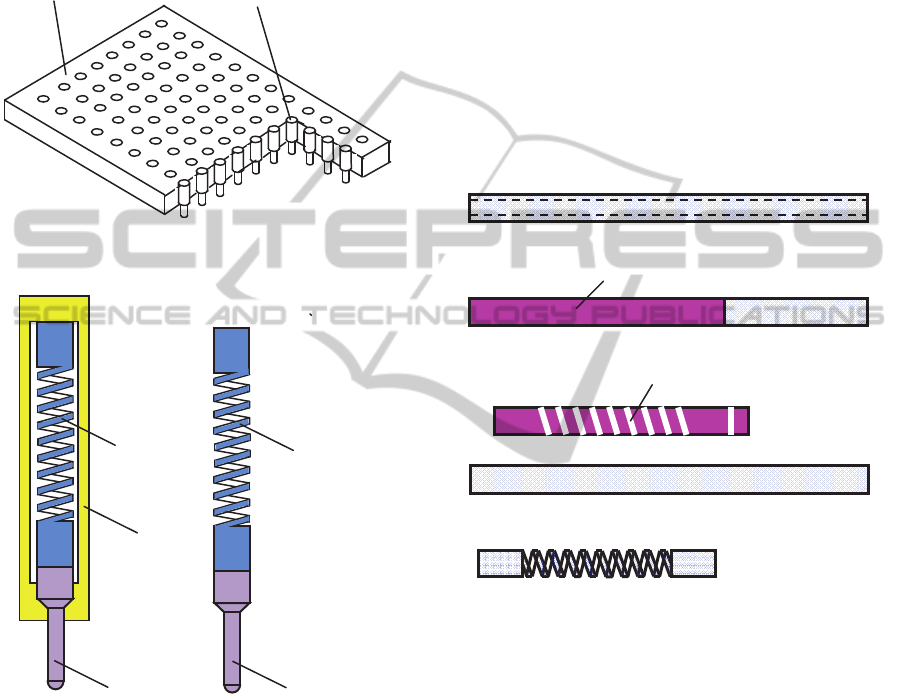
pins densely in an array, straight coil springs with a
small diameter are favourable.
In addition, micro-coils are also useful for
detecting various bio-signals in local narrow areas.
For this use, various types of sensing coils were
proposed (
Ramadan et al., 2006).
Electrodepin
Substrate
(Insulator)
Figure 1: Schematic figure of an electrode array.
Diameters and array size are deformed in the figure.
Barrel
Coilspring
Electrodepin
Coilspring
Electrode
p
in
(a) Built-in type (b) Naked type
Figure 2: Schematic figures of electrode pins for the use of
bio-sensing.
In such electrical measurement use, the micro-
coils should not be magnetisable, because induced
magnetic fields cause measurement errors. From this
point of view, coil-springs of non-magnetisable
materials are preferred.
On the other hand, micro-coils are also applied to
realize special magnetic actuators for biomedical use.
For example, actuators of micro-manipulator and
tweezers were presented (Barbic, 2002).
For the biomedical use, materials not becoming
rusty are very favourable in general, and strength
and durability for the repeating use are required
frequently. Considering these conditions, non-
magnetisable stainless steels are one of the most
appropriate materials.
3 FABRICATION METHOD OF
STAINLESS MICRO-COILS
3.1 Fabrication Process
Micro-coils were fabricated by the process shown in
Fig. 3. SUS304 stainless steel pipes with outer and
inner diameters of 100 and 60 μm and length of 50
mm were prepared as specimens.
(a) Preparation of a specimen pipe
(b) Resist coating
(c) Helical patterning
(d) Wet-etching
Figure 3: Micro-coil fabrication process.
They were coated with films of positive resist
PMER P LA900PM (Tokyo Ohka Kogyo) by the
dipping method. Using laser scan lithography,
helical coil patterns were delineated on the specimen
pipes. The patterned pipes were wetly etched in an
electrolytic etchant applying appropriate voltage.
Because the specimens were masked by the helical
resist patterns, they were etched into coils.
3.2 Laser Scan Lithography
Patterning principle of the laser-scan lithography
onto fine pipes is shown in Fig. 4. As a source,
semiconductor violet laser with a wavelength of 408
nm was used. Nominal output power of the laser was
15 mW. The ejected laser light beam was reshaped
using a pinhole with a diameter of 500 μm. The
Resist
Helical space patterns
FabricationofStraightStainless-SteelMicro-CoilsfortheUseofBiodeviceComponents
115
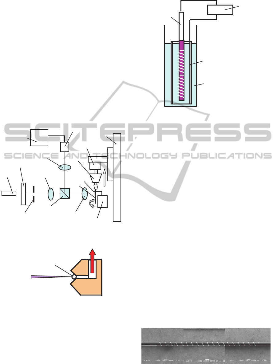
outlet of the pinhole was projected onto a specimen
pipe using the projection optics being composed of a
10X object lens and 2X imaging lens. Accordingly,
the laser spot size on the specimen was
approximately 25 μm. The specimen pipes and wires
were held and guided using a specially prepared half
vacuum chuck with a V-shape guide, as shown in
Fig. 5. The pipes were chucked at three separate
linear chucking vacuum ports. Because the
specimens were guided by the V-shape walls of the
chuck, the irradiated position of the laser beam was
maintained always constant, even if the specimens
were moved and rotated along the guide, or slightly
curved by nature before they were chucked.
Although the delineated pattern widths depended
on the laser beam spot size, they were considerably
adjusted by changing the scanning speed.
Vacuum
laser
Violet
Shutter
Imaginglens(1X)
Monitor
CCDcamera
Rotationstage
Chuck
guide
Imaginglens(2X)
Objectlens(10X)
Pinhole
Beamsplitter
Guideadjuststage
Linearstage
Display
Pipe
Figure 4: Principle of laser-scan exposure system.
Specimenpipe
Halfvacuum
Laserbeam
Figure 5: Principle of half-vacuum support guide.
3.3 Electrolytic Etching
Etching was performed holding the pipe specimen
vertically in an etchant bottle, and placing an
aluminium cylindrical cathode surrounding the
specimen. The specimen pipe was used as an anode,
as shown in Fig. 6. As an etchant, mixture of water,
sodium chloride (NaCl), ammonium chloride, and
boric acid was used. The etchant was heated on a
hotplate, and the temperature was kept at 40-60ºC.
Specimenpipe
(Anode)
−
Aluminumpipe
(Cathode)
Electrolyticetchant
(NaCl+NH
4
Cl+H
3
BO
3
+H
2
O
)
+
Power
supply
Figure 6: Schematic figure of dissociation etching.
4 FABRICATION OF
MICRO-COILS AND
EVALUATION
Micro-coils with a pitch of 150 μm, turn number of
20, and the length of 3 mm were fabricated, and the
accuracy was evaluated. In the lithography process,
the resist was coated in 4 μm thick, and the
delineation speed was set at 50 μm/s. The etching
time was determined by monitoring the electrolytic
etching voltage, and was approximately 40 s. The
resist patterns were removed after etching the
specimens by dipping them in the resist remover.
Figs. 7 and 8 show a patterned pipe and a
fabricated micro-coil. Space pattern widths along the
coil were almost constant, as shown in Fig. 9, and
the width variation was within ±1 μm for the mean
width of 15.5 μm. The error was almost equal to the
measurement error.
Resist patterns should have perpendicular
sidewalls to obtain the aimed widths stably with
good repeatability. From this point of view, the
resist patterns had favourite cross sections, as shown
in Fig. 10. This superiority probably comes from the
use of half-vacuum chuck and a fact that the
exposure beam spot size is kept always constant.
Figure 7: Helical pattern delineated on a specimen pipe.
BIODEVICES2013-InternationalConferenceonBiomedicalElectronicsandDevices
116
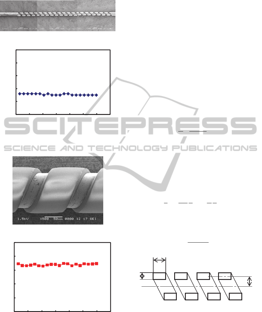
Figure 8: Micro-coil fabricated by electrolytic etching.
0
10
20
30
40
50
0 500 1000 1500 2000 2500 3000 3500
Position(μm)
Spacepatternwidth(μm)
Figure 9: Width variation of space patterns along the
specimen axis.
Figure 10: Sidewall profiles of a helical resist pattern.
0
20
40
60
80
100
0 500 1000 1500 2000 2500 3000 3500
Position(μm)
Spacepatternwidth(
μ
m)
Figure 11: Space width variation of a fabricated coil.
Because the pipes were undercut during the
etching, space widths of the fabricated coils were
wider than the space pattern widths, as shown in Fig.
11. The width differences between the resist pattern
and the coil were approximately equal to twice of
the pipe thickness. However, the coil space widths
were also almost homogeneous, and the deviation
was ±2 μm for the mean width of 68 μm. Because
the coil pitch was 150 μm, coil widths were
approximately 82 μm. It was also verified that
natural pipe parts were remained at both ends in
arbitrary lengths, if necessary.
5 SPRING CHARACTERISTICS
DEPENDENCE ON SIZES
Spring constant was calculated if micro-coils had
appropriate rigidity or flexibility. Spring constant k
was calculated by eq. (1) (Utoguchi et al., 1957).
3
3
2 nR
hbG
P
k
(1)
Here, P is the axial load [N],
δ
is the distortion [μm],
G is the shearing modulus [N/mm
2
], b is the
thickness of the coil [μm], h is the width of the coil
element [μm], n is the number, and R is the mean
radius, as shown in Fig. 12. β is the constant
dependent on the ratio of h/b, and calculated by eq.
(2) (Shibahara, 1977).
b
h
h
b
2
tanh
192
1
3
1
5
(2)
Since function tanh x is expressed by eq. (3), β is
calculated, as shown in Fig.13.
xx
xx
ee
ee
x
tanh
(3)
h
b
R
1
2...
n
Coil
number
Figure 12: Size parameters of a micro-coil.
When material pipes with an outer diameter of
100 μm, k was calculated, as shown in Figs. 14 and
15. Because k is proportional to 3rd power of b, the
rigidity largely changes depending on the pipe wall
thickness.
FabricationofStraightStainless-SteelMicro-CoilsfortheUseofBiodeviceComponents
117
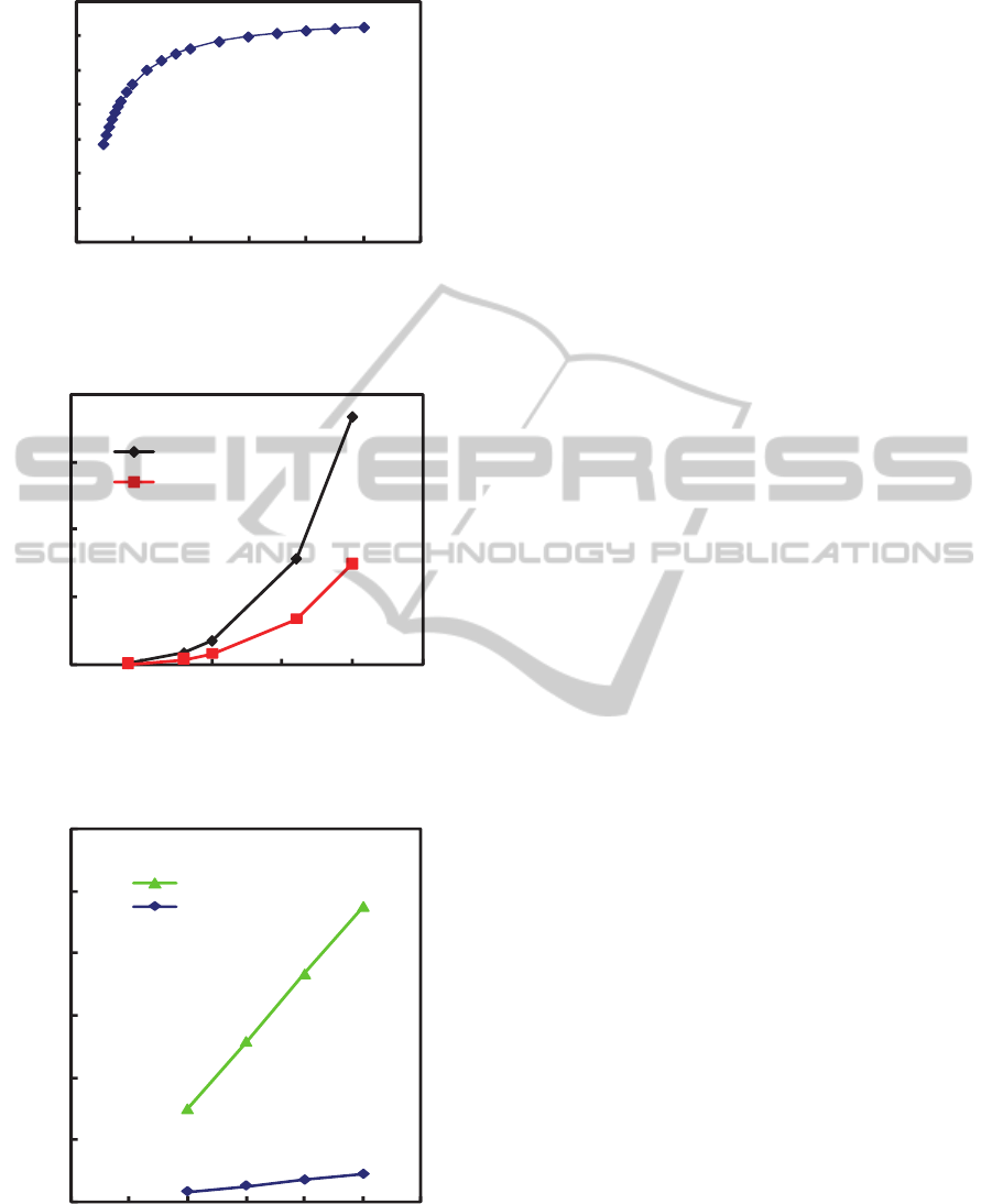
0
0.05
0.1
0.15
0.2
0.25
0.3
0.35
024681012
Sidelengthratioh/bofcoilcrosssection
Constantβ
Figure 13: Constant β used for the calculation of spring
constant.
Coilwidth
0
0.5
1
1.5
2
0 5 10 15 20 25
系列1
系列2
80μm
40μm
Wallthicknessofmaterialpipe(μm)
Springconstant(N/mm)
Figure 14: Spring constant dependence on wall thickness
of material pipe.
0
0.5
1
1.5
2
2.5
3
0 20406080100120
系列1
系列2
Coilwidth(μm)
20μm
10μm
Wallthicknessofmaterialpipe
Springconstant(N/m
m
)
Figure 15: Spring constant dependence on coil width.
Calculated spring constant values were in a
favourite range. However, perhaps it is felt
apprehensive that the coils are slightly too stiff. This
time, specimen pipes with a wall thickness of 20 μm
were used. However, pipes with a wall thickness of
10 μm are also commercially available. Therefore,
far flexible springs can also be fabricated, if
necessary.
Because the wall thickness is strictly cared by the
pipe maker, spring constant variation caused by the
wall thickness dispersion is very small. This is a
noteworthy advantage of this fabrication method.
On the other hand, k is simply proportional to the
width h of the coil element. Because h is
controllable by the scan exposure speed or the
etching time, the spring constant can be finely
adjustable by controlling h.
Required stiffness of the micro-coil spring
depends on the application. Therefore, it is
preferable that the spring constant can be easily
changed in a wide range.
6 CONCLUSIONS
Micro-coil springs of SUS304 stainless steel were
successfully fabricated by etching pipes masked by
helical patterns. Despite of the scan exposure, resist
patterns had good cross section profiles with
perpendicular sidewalls, and pattern width
fluctuation was small enough. This superiority
probably depends on the use of half-vacuum
specimen guide in the exposure system.
After the lithography, patterned pipes were finely
etched in the electrolytic etchant. Pattern width
variation in the longitudinal direction of the coil was
less than ±2 μm. Because the spring constant is
decided by the mean width of the coil, above width
fluctuation is permissible.
It was clarified that the spring constant was in an
expected range, and could be changed in
considerably wide ranges by selecting appropriate
shape parameters. The new stainless steel micro-
coils will be applicable to various bio-devices.
ACKNOWLEDGEMENTS
This work was partially supported by Research
Institute for Science and Technology of Tokyo
Denki University, Grant Number Q11T-01.
BIODEVICES2013-InternationalConferenceonBiomedicalElectronicsandDevices
118

REFERENCES
Barbic, M., 2002. Magnetic wires in MEMS and bio-
medical applications, Journal of Magnetism and
Magnetic Materials, 249, 357-367.
Horiuchi, T. and Sasaki, R., 2012. New Laser-Scan
Exposure System for Delineating Precise Helical
Patterns onto Sub-50-μm Wires, Japanese Journal of
Applied Physics, 51, 06FL01.
Horiuchi, T., Ishii, H., Shinozaki, and Y., Ogawa, T., 2011.
Laser Scan Lithography onto Fine Pipes and Wires
with Sub-100-nm Diameters, Journal of Photopolymer
Science and Technology, 24, 373-378.
Horiuchi, T., Ishii, H., Shinozaki, Y., Ogawa, T., and
Kojima, K., 2011. Novel Fabrication Method of
Microcoil Springs Using Laser-Scan Helical
Patterning and Nickel Electroplating, Japanese
Journal of Applied Physics, 50, 06GM10.
Honjo, H., Inada, S., Lancaster, M. K., Yamamoto, M.,
Niwa, R., Jones, S. A., Shibata, N, Mitsui, K.,
Horiuchi, T., Kamiya, K., Kodama, I., and Boyett, M.
R., 2003. Sarcoplasmic Reticulum Ca2+ Release Is
Not a Dominating Factor in Sinoatrial Node
Pacemaker Activity, Circulation Research, 1-4.
Honjo, H., Boyett, M. R., Niwa, R., Inada, S., Yamamoto,
M., Mitsui, K., Horiuchi, T., Shibata, N, Kamiya, K.,
and Kodama, I., 2003. Pacing Induced Spontaneous
Activity in Myocardial Sleeves of Pulmonary Veins
After Treatment With Ryanodine, Circulation, 1937-
1943.
Liu, Q., Yu, J., Xiao, L., Tang, J. C. O., Zhang, Y., Wang,
P., and Yang, M., 2009. Impedance studies of bio-
behavior and chemosensitivity of cancer cells by
micro-electrode arrays, Biosensors and Bioelectronics,
24, 1305-1310.
Ramadan, Q., Samper, V., Poenar, D. P., and Yu, C., 2006.
An integrated microfluidic platform for magnetic
microbeads separation and confinement, Biosensors
and Bioelectronics, 21, 1693-1702.
Shibahara, M., 1977. Zairyo Rikigaku (Strength of
Materials) Rikogaku-sha, 95-96.
Utoguchi, T., Kawada, Y., and Kuranishi, M.,1957. Zairyo
Rikigaku (Strength of Materials) Shokabo, 110-111.
FabricationofStraightStainless-SteelMicro-CoilsfortheUseofBiodeviceComponents
119
