
Real-time Video-based View Interpolation of Soccer Events using
Depth-selective Plane Sweeping
Patrik Goorts, Cosmin Ancuti, Maarten Dumont, Sammy Rogmans and Philippe Bekaert
Hasselt University, Expertise Centre for Digital Media, Wetenschapspark 2, 3590 Diepenbeek, Belgium
Keywords:
Sports Broadcasting, View Interpolation, Plane Sweep, Virtual Viewpoint, Real-time Processing.
Abstract:
In this paper we present a novel technique to synthesize virtual camera viewpoints for soccer events. Our
real-time video-based rendering technique does not require a precise estimation of the scene geometry. We
initially segment the dynamic parts of the scene to consequently estimate a depth map of the filtered foreground
regions using a plane sweep strategy. The depth map is indicatively segmented to depth information per
player. A consecutive plane sweep is used, where the depth sweep is limited to the depth range of each player
individually, effectively removing major ghosting artifacts, such as third legs or ghost players. The background
and shadows are interpolated independently. For maximum performance our technique is implemented using a
combination of NVIDIA’s shaders language Cg and NVIDIA’s general purpose computing framework CUDA.
The rendered results of an actual soccer game demonstrate the usability and accuracy of our framework.
1 INTRODUCTION
Nowadays, the demand for high-quality footage of
sport events is higher than ever. Current caption sys-
tems therefore deliver high definition video in real-
time. However, the viewpoints of these traditional
systems are in general limited to the position of the
physical cameras. In order to provide additional novel
views from arbitrary positions in the scene, we de-
velop a method that is able to synthesize virtual views
in real-time. Compared with the traditional acqui-
sition systems, our technique has the advantage to
provide additional important features such as creat-
ing pleasant looking camera transitions, time freezing
and interaction to the end users.
Our technique is a fully automatic real-time video-
based method that generates images of virtual cam-
era viewpoints, roughly placed in between physical
cameras being demonstrated for a real soccer game.
Video- and Image-based rendering techniques (IBR)
represent a powerful alternative to geometry-based
techniques to generate novel views. In contrast to ac-
curately modeling the geometry, IBR techniques al-
low to visualize 3D environments using only the in-
formation of the captured images.
Our proposed method uses cameras with a fixed
position in a semi-wide baseline setup, which is larger
than a typical interpolation setup. In our framework,
the dynamic parts (players) are first segmented and
consequently rendered independent from the back-
ground. Since we target a fast technique, a depth
map of the filtered foreground regions is calculated
using a plane sweep strategy. This initial depth map
is employed to estimate the depth range of every
player. Finally, the foreground is rendered using a
depth-selective plane sweep, thus limiting the player-
dependent depth range based on the previously calcu-
lated depth range of the foreground objects. This will
provide a detailed depth map of every player without
disturbing artifacts, while respecting its global depth.
This novel interpolated image of the foreground is
then merged with the interpolated background.
All algorithms are implemented using a combina-
tion of NVIDIA’s Cg shader language and NVIDIA’s
general purpose computing framework CUDA and
exploiting it’s interoperability. This combination
allows for maximum performance by using the
strengths of both frameworks and hiding the weak-
nesses (Rogmans et al., 2009b).
To demonstrate our method, we obtained video
streams from a real soccer match using computer
vision cameras placed approximately 1 meter apart
from each other. Thanks to commodity graphics hard-
ware and our parallel algorithmic approach, the in-
terpolated view is obtained in real-time. The results
show high-quality interpolation without typical inter-
polation artifacts, such as extra limbs, ghost players,
distorted parallax effects or warping errors.
131
Goorts P., Ancuti C., Dumont M., Rogmans S. and Bekaert P..
Real-time Video-based View Interpolation of Soccer Events using Depth-selective Plane Sweeping.
DOI: 10.5220/0004217301310137
In Proceedings of the International Conference on Computer Vision Theory and Applications (VISAPP-2013), pages 131-137
ISBN: 978-989-8565-48-8
Copyright
c
2013 SCITEPRESS (Science and Technology Publications, Lda.)
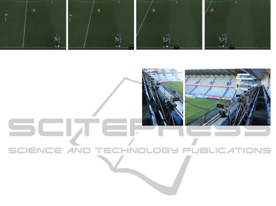
Figure 1: Examples of input images on positions 0, 1, 6 and 7.
In Section 2, we will discuss the context of our
work using related work. In Section 3, a detailed
description of our setup is given. The prerendering
phase of the method is elaborated in Section 4 and the
real-time rendering phase in Section 5. Finally, the
results are presented in Section 6, together with the
conclusions in Section 7.
2 RELATED WORK
To generate novel views, the existing methods are
divided in two main classes: geometry-based ren-
dering techniques and image-based rendering (IBR)
techniques. When using geometry, the scene is re-
constructed as a collection of 3D models. Visual hull
(Matusik et al., 2000; Miller et al., 2005), photo hull
(Kutulakos and Seitz, 2000) and space carving (Seitz
and Dyer, 1999) are the most known strategies of this
approach.
Some attempts transfer the studio-based recon-
struction techniques for the outdoor sport events. One
of these examples is the Eye vision system (eye, 2001)
used to record the Super Bowl 2001 described in the
work of Kanade et al. (Kanade et al., 1997). They
used thirty motorized camera heads slaved to a single
manually controlled camera to produce sweep shots
with visible jumps between viewpoints. The frame-
work of Hilton et al.(Hilton et al., 2011) reconstructs
a 3D scene proxy at each frame starting with a vol-
umetric reconstruction followed by a view-dependent
refinement using information from multiple views.
On the other hand, image-based rendering tech-
niques aim to visualize 3D scenes and objects in
a realistic way by replacing the geometry and sur-
face properties only with images. In contrast with
geometry-based rendering techniques, IBR methods
are more robust requiring more simpler and inexpen-
sive setups. The most known approach is the gen-
eration of depth maps for small baseline setups us-
ing stereo matching (Seitz et al., 2006; Zitnick et al.,
2004) and plane sweeping (Yang et al., 2004; Dumont
et al., 2009), including depth-selective sweeping for
two views (Rogmans et al., 2009a). Our method also
Figure 2: Overview of the camera setup. The setup consists
of 8 computer vision cameras with 25mm lenses placed 1
meter apart from each other.
belongs in the latter category of rendering techniques.
There have been several view interpolation sys-
tems that have been designed for soccer games. iView
(Grau et al., 2007), commercialized by Red Bee Me-
dia(red, 2001), uses a narrow baseline camera setup
and billboards or visual hulls to generate novel view-
points of the soccer players. Shadow is synthetically
applied to the result. However, some serious arti-
facts are reported when using the proposed methods,
e.g. ghosting, flickering, missing limbs and blurred
images.
Ohta et al.(Ohta et al., 2007) developed a tech-
nique that processes a simplified 3D model built on
billboards. Hayashi and Saito (Hayashi and Saito,
2006; Inamoto and Saito, 2007) employ as well a bill-
board representation of dynamic regions while the in-
terpolation is performed by estimating the projective
geometry among different views. A similar method
has been proposed recently by Germann et al. (Ger-
mann et al., 2010) that estimate the 2D pose using
a database of silhouettes. Based on the pose and
segmentation, the articulated billboard model is op-
timized in order to compensate for errors. Different
than our approach, this technique requires manual in-
tervention.
3 FRAMEWORK SETUP
To generate input video streams for our method, we
created a setup consisting of an array of 8 Basler
VISAPP2013-InternationalConferenceonComputerVisionTheoryandApplications
132
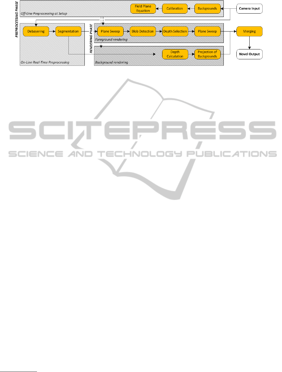
Figure 3: Overview of our method. There are two phases: a preprocessing phase, including calibration and background
extraction, and a real-time rendering phase, where the foreground and the background are rendered independently.
avA1600-50gc
1
computer vision cameras with 25mm
lenses. The cameras are placed approximately 1 me-
ter from each other, while the distance to the field is
approximately 20 meters (see Figure 2). The cameras
are triggered externally to provide global synchro-
nization between the image streams. To provide high-
quality results, the recording was done at 30 images
per second with a resolution of 1600 × 1200. Figure
1 shows some example input images.
The raw images captured by the cameras C
r
i
are
transmitted to a rendering computer using a 10 Giga-
bit Ethernet connection. The rendering computer al-
lows to choose the location of a virtual camera C
v
that,
as will be described in the following, is processed in
real-time. To acquire real-time processing, the com-
puter is equipped with an NVIDIA GeForce GTX 580
running at 1544 MHz.
An overview of our method is shown in Figure 3.
The method consists of two main phases: a prepro-
cessing and a real-time rendering phase. These main
tasks are discussed in the subsequent sections.
4 PREPROCESSING PHASE
In the first step of our technique the camera posi-
tions are calibrated. This step is performed based
on SIFT (Lowe, 2004) local feature points that are
detected in the scene to generate camera correspon-
dences. First, SIFT features are extracted from all in-
put images C
i
. Next, these features are matched be-
tween pairs of cameras using the k-d tree algorithm
that searches similar features based on their clos-
est distance. The pairwise correspondences are then
tracked across multiple cameras using a graph-based
search algorithm. The filtered matches are then used
to calculate the position, orientation and the intrinsic
parameters of the cameras based on the well-known
techniques of Svoboda et al. (Svoboda et al., 2005).
1
http://www.baslerweb.com/products/
aviator.html?model=204
This method consists of hole-filling to deal with oc-
clusions and a bundle adjustment with RANSAC. The
invalid matches from the previous steps are removed
based on the RANSAC procedure.
Moreover, we calculate the position, represented
as a plane equation, of the field. In our strategy this
equation is acquired by manually selecting several
matches (about 10 matches) on the field across all
camera images C
i
and using these matches to trian-
gulate 3D points on the field. More correspondences,
sparsely spreaded over the field, result in a more ac-
curate estimation of the field. Afterwards, standard
plane fitting is used to acquire the plane equation
(Hartley and Zisserman, 2003), usable as a geomet-
ric representation of the field.
Furthermore, in this preprocessing step, back-
grounds B
i
are calculated using a per-pixel median
filter. In order to provide a robust background gener-
ation, approximately 30 images are captured at a rate
of 2 frames per minute right before the actual record-
ing. When the lighting changes in the scene, it might
be required to repeat this procedure during the pro-
cessing using a subset of the captured images.
5 REAL-TIME RENDERING
PHASE
Our real-time rendering phase consists of four parts:
frame preprocessing, background rendering, fore-
ground rendering and merging.
5.1 Frame Preprocessing
When running the setup, every acquired frame must
be preprocessed before the actual rendering step.
These steps include debayering and segmentation.
Firstly, the raw input images C
r
i
(i ∈ [1, N]) need
to be debayered. The cameras provide raw images,
where every pixel only contains the value of one
color channel. The color is defined by the specific
Real-timeVideo-basedViewInterpolationofSoccerEventsusingDepth-selectivePlaneSweeping
133
color pattern used in the camera sensor, i.e. the Bayer
pattern. The values of the other color channels of
the pixel are interpolated using the surrounding pixel
values. This is done by uploading the raw image
to the GPU and applying the AHD method of Hi-
rakawa and Parks (Hirakawa and Parks, 2005), coded
in NVIDIA’s shader language Cg. By using our own
GPU implementation of debayering, we avoid uncon-
trolled and lower quality processing on camera hard-
ware, reduce the amount of camera-computer data
copying with a factor three, and therefore increase the
arithmetic intensity of the GPU by making the results
locally available for the subsequent algorithms.
Secondly, the debayered images C
i
are segmented
on the GPU using the backgrounds B
i
of the pre-
rendering step. To provide real-time processing, the
segmentation is processed on a pixel basis and uses
thresholds τ
f
, τ
b
, τ
a
, with τ
f
> τ
b
:
s
i
=
1 : τ
f
< kc
i
− b
i
k
1 : τ
f
≥ kc
i
− b
i
k ≥ τ
b
and cos(
d
c
i
b
i
) ≤ τ
a
0 : kc
i
− b
i
k < τ
b
0 : τ
f
≥ kc
i
− b
i
k ≥ τ
b
and cos(
d
c
i
b
i
) > τ
a
(1)
with s
i
= S
i
(x, y), c
i
= C
i
(x, y) and b
i
= B
i
(x, y),
for all pixels (x, y).
d
c
i
b
i
is the angle between the fore-
ground and background color. We measure the dif-
ference between the foreground and background pix-
els. When the difference is large (larger than τ
f
), the
pixel is considered as foreground. If the difference
is small (smaller than τ
b
), the pixel is considered as
background. When the difference is in between these
thresholds, we consider the vector angle between the
colors and apply the threshold τ
a
. Finally, the seg-
mentation is enhanced with an erosion and dilation
step to reduce small segmentation errors caused by
noise in the input streams (Yang and Welch, 2002).
The thresholds should be chosen such that the
foreground objects, like players and the ball, are con-
sidered as foreground, but the shadows are considered
as background. The shadows are in essence a darker
background, while foregrounds do not correlate with
the background, thus allowing the use of thresholds.
We do not consider shadow as foreground to re-
duce interpolation artifacts caused by mismatches in
shadow regions. Shadows are located on the back-
ground, thus eliminating the need for separate inter-
polation; the shadows are interpolated together with
the background.
After these preprocessing steps, the background
B
v
and foreground F
v
of the virtual view are rendered
independently.
Figure 4: Principle of plane sweeping. The space before the
virtual camera C
v
is discretized in planes. For every depth
D
j
, every pixel of the virtual view is deprojected on this
plane and back projected on every input camera C
1
− C
6
.
Using these color values, a cost error ε can be calculated,
thus deriving the optimal depth for that virtual pixel.
5.2 Background Rendering
To generate the background B
v
of the virtual image,
we take the input images C
i
and replace the fore-
ground pixels with the values from the background
images B
i
, according to the segmentation. This will
preserve the shadows of the objects, while removing
foreground pixels which can cause artifacts.
These generated frame backgrounds are then pro-
jected and blended on the plane as determined in the
preprocessing phase. The projection is dependent of
the parameters of the input cameras and the parame-
ters of the current virtual view and should be repeated
for every frame.
5.3 Initial Plane Sweeping
The foreground F
v
is rendered in three passes. First, a
global plane sweep is performed to generate a crude
depth map and segmentation of the virtual viewpoint.
Our plane sweep is an adopted and modified version
of the well-known method from Yang et al. (Yang
et al., 2003). The world before the virtual camera
is divided in M planes of depths D
p
∈ [D
min
, D
max
],
parallel to the virtual image plane, as can be seen in
Figure 4. For every plane, every pixel v(x, y) of the
virtual camera image is deprojected on this plane, re-
projected on the input images and the error ε is calcu-
lated per pixel and per depth plane using the sum of
VISAPP2013-InternationalConferenceonComputerVisionTheoryandApplications
134

squared differences (SSD):
ε =
N
∑
i=1
kγ −C
i
k
2
3N
with γ =
N
∑
i=1
C
i
N
(2)
where γ is the average of the reprojected pixels and
C
i
is the i
th
input image of total N. When a reprojected
pixel falls outside the segmentation mask, the error
ε for that depth is set to infinity. This will guaran-
tee consistency with the segmentation. The resulting
depth d
l
for a virtual pixel is the depth plane on depth
D
l
with the lowest error ε for that virtual pixel, and
the color is the average γ of the corresponding pixels
in the input images. When every ε is infinity, the pixel
in the virtual image is considered as background. The
calculation of the depth map and the resulting color
image can efficiently be implemented using Cg on
graphics hardware by exploiting the projective tex-
turing capabilities, resulting in real-time processing
(Dumont et al., 2009).
5.4 Depth Selection
After the initial plane sweep, we select a depth range
per player visible in the virtual view. The depth map
is split up in unconnected blobs of pixels. These rep-
resent an independent player or a group of players.
This is achieved using a parallel region growing al-
gorithm created for CUDA (Ziegler and Rasmusson,
2010). Initially, every pixel is assigned an unique
label. Next, we assign one thread per pixel. Every
thread will compare the label of its neighboring pix-
els with its own label and will assign the lowest of
the two to itself. Neighboring pixels that originate
from the background are ignored. This process is re-
peated until no more changes are made. Now every
foreground pixel has a label that is the same as ev-
ery other connected pixel. Pixels with the same label
form one distinct blob or foreground object. Every
detected object is then filled with the median of the
depth values of that object. This depth represents the
global depth d
l
of the player (or group of players) in
that foreground object. CUDA is used to harness the
utilization of a user-managed cache, allowing more
efficient memory management than can be obtained
by normal texture lookups (Goorts et al., 2009). By
exploiting the interoperability of Cg and CUDA, no
performance penalty is perceived.
5.5 Depth-selective Plane Sweeping
Finally, this filtered depth map is used in a second
“depth-selective plane sweep”, extending the stereo
principle of Rogmans et al. (Rogmans et al., 2009a).
While sweeping over the range of depth values D
p
∈
[D
min
, D
max
], only values within a certain fraction α
of the depths d
l
calculated in the previous step are
accepted if the following expression is satisfied:
|
D
p
− d
l
|
< α(D
max
− D
min
) (3)
Depths that are not accepted are explicitly as-
signed an error ε of infinity. If every error is infinity,
the virtual pixel will be considered as background, re-
moving artifacts caused by mismatching.
This assures a detailed depth map of the player,
while respecting its global depth. Extra limbs and
other ghosting artifacts are filtered out using this
method. Indeed, these arise from errors in the match-
ing process of the first plane sweep. For example,
the left leg of one player is matched to his right leg,
resulting in a third leg in the virtual view (this can be
seen in Figure 7 (a)). However, the depth of this ghost
leg is distinct from the depth of the correct pixels of
the player. Using our method, this depth is filtered out
and the ghost leg is considered as background. Small
artifacts due to errors in the reprojection are reduced
by limiting the depth range per player, thus obtaining
a high quality depth map without large errors in the
individual depth values.
While the former method will remove many arti-
facts, some artifacts can not be eliminated. Errors in
the matching process can result in the manifestation
of ghost players, i.e. when one player of one camera
image matches to another player in another camera.
However, in our experiments this rarely happens due
to our segmentation constraints. The depth filtering
will not eliminate these artifacts, because these are
disconnected from other desirable blobs of players.
Therefore, we also consider the depth of the back-
ground and remove every pixel where the depth devi-
ates more than a certain range β from the depth of the
background on that pixel. Because the background
is a plane and the foreground is related to the back-
ground, this method will effectively filter out extreme
mismatches in the foreground.
5.6 Merging
The rendering of the foreground F
v
and background
B
v
are then merged using the segmentation obtained
from the second plane sweep. To generate a pleasant-
looking result, the borders of the foreground are
slightly feathered and blended with the background.
6 RESULTS
Figure 5 shows interpolated views of a frozen frame.
Figures 6, 7 and 8 show some detailed results of our
Real-timeVideo-basedViewInterpolationofSoccerEventsusingDepth-selectivePlaneSweeping
135
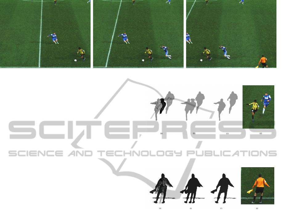
Figure 5: Final results of the method for a frozen frame. The positions are 0.5, 3.5 and 6.5.
method for different scenes. Figure 6a, 7a and 8a
show the resulting depth map of normal plane sweep-
ing. These depth maps contain significant noise and
artifacts, which reduce the quality of the final results.
The first filtering process applied in our strategy
consists of filtering the depth values per connected
blobs of pixels, as explained in Subsection 5.3. We
fixed the parameters of the method for every result on
0.01 for α and 0.2 for β. Figure 6b and 7b show the
depth map after foreground object detection and cal-
culating the median per object. Notice that only the
depth values are altered and artifacts (like a ghost leg
in Figure 7b) are still present. However, these artifacts
now have a very different depth value than the origi-
nal value. The final depth maps and the results after
the depth-selective plane sweep are shown in Figure
6c-d and 7c-d. Notice that after the filtering stage the
results are sharp and no visible artifacts are present.
Figure 8a and 8e show artifacts that can not be
removed with this filtering strategy. Here, an arti-
fact is visible in between the two players and is not
filtered out after the second plane sweep, as can be
seen in Figure 8b. When we use the depth informa-
tion (Figure 8c) of the background and remove every
blob where the depth value differs too much, we are
able to remove these artifacts also, as can be seen in
Figure 8d.
By using depth filtering, we effectively remove
large artifacts. The small artifacts, such as wrong col-
ors by reprojection errors, are removed due to the high
quality depth map obtained by the depth-selective
plane sweep.
7 CONCLUSIONS
In this paper, we presented a new method to acquire
interpolated views from a soccer game for physical
cameras in a semi-wide baseline setup. We firstly es-
timate the depth of every player and then refine this
depth, which allows the generation of a high quality
interpolated view of the players. The background and
Figure 6: Detail of the method: (a) Depth map of stan-
dard plane sweep. (b) Filtered depth. (c) Depth map of the
depth-selective plane sweep. The artifacts are effectively
removed. (d) Final merged result.
Figure 7: Detail of the method: (a) Depth map of standard
plane sweep. (b) Filtered depth. (c) Depth map of the depth-
selective plane sweep. The ghost leg and other artifacts are
effectively removed. (d) Final merged result.
shadows are generated separately using a geometry-
based interpolation. The main advantage of our tech-
nique is that the entire pipeline is implemented using
graphics hardware, which allows real-time processing
and interpolation. A one-time camera calibration and
background generation step is required at setup.
The results show that the method yields high-
quality results without disturbing ghosting artifacts,
parallax errors, etc., which most image-based algo-
rithms suffer from.
ACKNOWLEDGEMENTS
Patrik Goorts would like to thank the IWT for its PhD
specialization bursary.
VISAPP2013-InternationalConferenceonComputerVisionTheoryandApplications
136
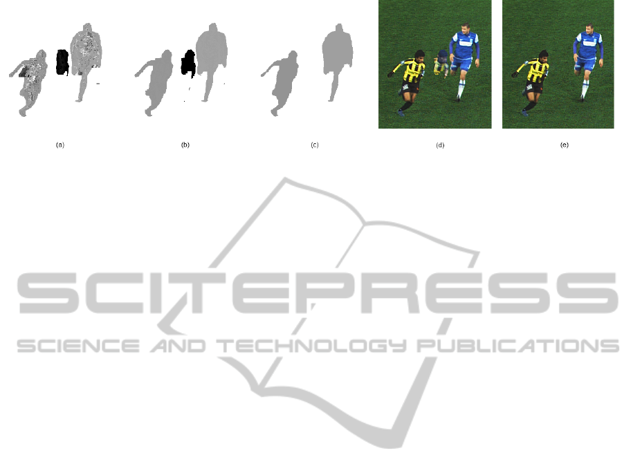
Figure 8: Detail of the method: (a) Depth map of standard plane sweep. (b) Filtered depth map after the depth-selective plane
sweep. Not all artifacts are removed. The depth of the artifact differs a lot from the depth of the background. (c) Depth after
the depth-selective plane sweep after the removal of the artifact. (d) Result without filtering using the background depth. (e)
Result with filtering using the background depth.
REFERENCES
(2001). 3d graphics systems by red bee media. http://
redbeemedia.com/html/live-graphic.html.
(2001). Eye vision at the super bowl. http://
www.ri.cmu.edu/events/sb35/tksuperbowl.html.
Dumont, M., Rogmans, S., Maesen, S., and Bekaert, P.
(2009). Optimized two-party video chat with restored
eye contact using graphics hardware. e-Business and
Telecommunications, pages 358–372.
Germann, M., Hornung, A., Keiser, R., Ziegler, R.,
W
¨
urmlin, S., and Gross, M. (2010). Articulated bill-
boards for video-based rendering.
Goorts, P., Rogmans, S., and Bekaert, P. (2009). Opti-
mal Data Distribution for Versatile Finite Impulse Re-
sponse Filtering on Next-Generation Graphics Hard-
ware using CUDA . In Proc. of The Fifteenth
Intl. Conference on Parallel and Distributed Systems,
pages 300–307.
Grau, O., Hilton, A., Kilner, J., Miller, G., Sargeant, T., and
Starck, J. (2007). A Free-Viewpoint Video System for
Visualization of Sport Scenes. SMPTE motion imag-
ing journal, 116(5/6):213.
Hartley, R. and Zisserman, A. (2003). Multiple view geom-
etry in computer vision, volume 2. Cambridge Univ
Press.
Hayashi, K. and Saito, H. (2006). Synthesizing Free-
Viewpoing Images from Multiple View Videos in Soc-
cer Stadium. In Intl. Conf. on Computer Graphics,
Imaging and Visualisation, pages 220–225.
Hilton, A., Guillemaut, J., Kilner, J., Grau, O., and Thomas,
G. (2011). 3d-tv production from conventional cam-
eras for sports broadcast. IEEE Transactions on
Broadcasting, (99):1–1.
Hirakawa, K. and Parks, T. (2005). Adaptive homogeneity-
directed demosaicing algorithm. Image Processing,
IEEE Transactions on, 14(3):360–369.
Inamoto, N. and Saito, H. (2007). Virtual viewpoint re-
play for a soccer match by view interpolation from
multiple cameras. IEEE Transactions on Multimedia,
9(6):1155–1166.
Kanade, T., Rander, P., and Narayanan, P. (1997). Virtu-
alized reality: Constructing virtual worlds from real
scenes. Multimedia, IEEE, 4(1):34–47.
Kutulakos, K. and Seitz, S. (2000). A theory of shape
by space carving. Intl. Journal of Computer Vision,
38(3):199–218.
Lowe, D. (2004). Distinctive image features from scale-
invariant keypoints. Intl. journal of computer vision,
60(2):91–110.
Matusik, W., Buehler, C., Raskar, R., Gortler, S., and
McMillan, L. (2000). Image-based visual hulls.
Miller, G., Hilton, A., and Starck, J. (2005). Interactive
free-viewpoint video.
Ohta, Y., Kitahara, I., Kameda, Y., Ishikawa, H., and
Koyama, T. (2007). Live 3D Video in Soccer Stadium.
Intl. Journal of Computer Vision, 75(1):173–187.
Rogmans, S., Dumont, M., Cuypers, T., Lafruit, G., and
Bekaert, P. (2009a). Complexity reduction of real-
time depth scanning on graphics hardware.
Rogmans, S., Dumont, M., Lafruit, G., and Bekaert, P.
(2009b). Migrating real-time depth image-based ren-
dering from traditional to next-gen gpgpu.
Seitz, S., Curless, B., Diebel, J., Scharstein, D., and
Szeliski, R. (2006). A comparison and evaluation of
multi-view stereo reconstruction algorithms.
Seitz, S. and Dyer, C. (1999). Photorealistic scene recon-
struction by voxel coloring. Intl. Journal of Computer
Vision, 35(2):151–173.
Svoboda, T., Martinec, D., and Pajdla, T. (2005). A conve-
nient multicamera self-calibration for virtual environ-
ments. Presence: Teleoperators & Virtual Environ-
ments, 14(4):407–422.
Yang, R., Pollefeys, M., Yang, H., and Welch, G. (2004). A
unified approach to real-time, multi-resolution, multi-
baseline 2d view synthesis and 3d depth estimation
using commodity graphics hardware. Intl. Journal of
Image and Graphics, 4(4):627–651.
Yang, R. and Welch, G. (2002). Fast image segmentation
and smoothing using commodity graphics hardware.
Journal of graphics tools, 7(4):91–100.
Yang, R., Welch, G., and Bishop, G. (2003). Real-time
consensus-based scene reconstruction using commod-
ity graphics hardware.
Ziegler, G. and Rasmusson, A. (2010). Efficient volume
segmentation on the gpu.
Zitnick, C., Kang, S., Uyttendaele, M., Winder, S., and
Szeliski, R. (2004). High-quality video view interpo-
lation using a layered representation.
Real-timeVideo-basedViewInterpolationofSoccerEventsusingDepth-selectivePlaneSweeping
137
