
3D Face Pose Tracking using Low Quality Depth Cameras
Ahmed Rekik
1
, Achraf Ben-Hamadou
2
and Walid Mahdi
1
1
Sfax University, Multimedia InfoRmation systems and Advanced Computing Laboratory (MIRACL),
P
ˆ
ole Technologique de Sfax, Route de Tunis Km 10, BP 242, 3021 Sfax, Tunisia
2
Paris-Est University, LIGM (UMR CNRS), Center for Visual Computing,
Ecole des Ponts ParisTech, 6-8 Av. Blaise Pascal, 77455 Marne-la-Vall
´
ee, France
Keywords:
3D Face Tracking, RGB-D Cameras, Visibility Constraint, Photo-consistency, Particle Filter.
Abstract:
This paper presents a new method for 3D face pose tracking in color image and depth data acquired by RGB-D
(i.e., color and depth) cameras (e.g., Microsoft Kinect, Canesta, etc.). The method is based on a particle filter
formalism. Its main contribution lies in the combination of depth and image data to face the poor signal-to-
noise ratio of low quality RGB-D cameras. Moreover, we consider a visibility constraint to handle partial
occlusions of the face. We demonstrate the accuracy and the robustness of our method by performing a set of
experiments on the Biwi Kinect head pose database.
1 INTRODUCTION
3D face pose tracking is becoming an important
task for many research domains in computer vision
like Human-Computer Interaction and face analy-
sis (Weise et al., 2011; Cai et al., 2010; Maurel
et al., 2008) and recognition (Kim et al., 2008).
Indeed, these research fields have dramatically in-
creased these very last years. This arises particularly
from the ubiquity of vision systems in our day life
(i.e., webcams in laptops, smart-phones, etc.) and
lately from the arrival of low-cost RGB-D cameras,
such as Microsoft Kinect and Canesta. Such new
cameras allow for synchronously capturing a color
image and a depth map of the scene with a rate of
about 30 acquisitions per second.These cameras pro-
vide a lower quality and much more noisy data that
bulky 3D scanners. However, they are efficient in sev-
eral domains like gesture recognition and video gam-
ing. Kinect is a good example. Nowadays, many
applications use Kinect-like cameras. For example,
(Weise et al., 2011) try to customize avatars using
Kinect data and (Ramey et al., 2011) use Kinect cam-
eras to interact with machines (e.g., robots and com-
puters).
This paper aims at developing a new method for
3D face pose tracking in color and depth images ac-
quired from Kinect like cameras using a particle filter
formalism. Our method is robust to the poor signal-
to-noise ratio of such cameras. The main idea is
to combine depth and image data in the observation
model of the particle filter. Moreover, we handle par-
tial occlusions of the face by integrating a visibility
constraint in the observation model.
This paper is organized as follows. In the next
section, we present the previous work related to 3D
face pose tracking using color images and/or depth
maps. Then, we detail our tracking method in section
3. Finally, section 4 presents the experiments and the
results obtained for the evaluation of our method.
2 RELATED WORK
Several research works have been proposed in the lit-
erature for face pose estimation and tracking. These
can be broadly categorized into 2D image or depth
data based approaches.
The first category gathers approaches that use
2D images to estimate the face pose. It refers to
the Appearance and Feature based methods. While
Appearance-based methods attempt to use holistic fa-
cial appearance (Morency et al., 2003), Feature-based
methods rely on the localization of specific facial fea-
tures and suppose that some of these are visible in all
poses (Yang and Zhang, 2002; Matsumoto and Zelin-
sky, 2000). In general, these methods suffer from par-
tial occlusions and are sensitive to the accuracy of fea-
ture detection methods.
223
Rekik A., Ben-Hamadou A. and Mahdi W..
3D Face Pose Tracking using Low Quality Depth Cameras.
DOI: 10.5220/0004220202230228
In Proceedings of the International Conference on Computer Vision Theory and Applications (VISAPP-2013), pages 223-228
ISBN: 978-989-8565-48-8
Copyright
c
2013 SCITEPRESS (Science and Technology Publications, Lda.)

Depth data based approach, however, rely only on
depth data to estimate the 3D face pose. Weise et
al. (Weise et al., 2011) use Iterative Closest Point
(ICP) with point-plane constraints and a temporal fil-
ter to track the head pose in each frame. In (Fanelli
et al., 2011), Fanelli et al. present a system for es-
timating the orientation of the head from depth data
only. This approach is based on discriminative ran-
dom regression forests, given their capability to han-
dle large training datasets. Another approach is pre-
sented in (Breitenstein et al., 2008) where a shape sig-
nature is first used to identify the nose tip in depth im-
ages. Then, several face pose hypotheses (pinned to
the localized nose tip) are generated and evaluated to
choose the best pose among them. These methods are
very sensitive to highly noisy depth data. Indeed, it is
difficult to distinguish the face regions in highly noisy
data.
Recently, (Cai et al., 2010) have used both depth
and appearance cues for tracking the head pose in-
cluding facial deformations. This idea behind the
combination of 2D images and depth data is to over-
come the poor signal-to-noise ratio of low-cost RGB-
D cameras. Their approach relies on detecting and
tracking facial features in 2D images. Assuming that
the RGB-D camera is already calibrated, one can find
the corresponding 3D coordinates of these detected
features. Finally, a generic deformable 3D face is
fitted to the obtained 3D points. Nonetheless, this
method does not handle partial occlusions of the face.
Moreover, like Feature based methods, it is sensitive
to the accuracy of feature detection and tracking al-
gorithms. In the same vein, Seemann et al. (Seemann
et al., 2004) present a face pose estimation method
based on a trained neural networks to compute the
head pose from grayscale and disparity maps. Sim-
ilar to the method proposed by (Cai et al., 2010), this
method does not handle partial occlusions of the face.
This paper presents a new Appearance-Based
method for 3D face pose tracking in sequences of im-
age and depth data. To cope with noisy depth maps
provided by the RGB-D cameras, we use both depth
and image data in the observation model of the parti-
cle filter. Unlike (Cai et al., 2010), our method does
not rely on tracking 2D features in the images to esti-
mate the face pose. Instead, we have used the whole
visible texture of the face. In this way, the method
is less sensitive to the quality of the feature detection
and tracking in images. Moreover, our method han-
dles the case of facial partial occlusions by introduc-
ing a visibility constraint.
3 3D FACE POSE TRACKING
METHOD
Our tracking method is based on the Particle filter
formalism which is a Bayesian sequential importance
sampling technique. It recursively approximates the
posterior distribution using a set of N weighted parti-
cles (samples). In the case of 3D face pose tracking,
particles stand for 3D pose hypotheses (i.e., 3D posi-
tion and orientation of the face in the scene). For a
given frame t, we denote X
t
= {x
i
t
}
N
i=1
the set of par-
ticles and x
i
t
∈ R
6
is the i-th generated particle that
involves the 6 Degrees of Freedom (i.e., 3 translations
and 3 rotation angles) of a 3D rigid transformation.
The general framework of the particle filter is to
throw an important number N of particles to populate
the parameter space, each one representing a 3D face
pose. The observation model allows for computing a
weight w
i
t
for each particle x
i
t
according to the simi-
larity of the particle to the reference model and using
the observed data y
t
in frame t (i.e., color and depth
images). Thus, the posterior distribution p(x
i
t
| y
t
)
is approximated by the set of the weighted particles
{x
i
t
, w
i
t
} with i ∈ {1, . . . , N}.
The transition model allows for propagating particles
between two consecutive frames. Indeed, at a current
frame t, particles ˆx
t−1
are assumed to approximate the
previous posterior. To approximate the current pos-
terior, each particle is propagated using a transition
model approximating the process function:
x
t
= ˆx
t−1
+ u
t
, (1)
where u
t
is a random vector having a normal distribu-
tion N (0, Σ) and the covariance matrix Σ is set exper-
imentally according to the prior knowledge on the ap-
plication. For instance, in Human-Computer Interac-
tion, the head displacements between two consecutive
frames are small and limited. Therefore, the values of
Σ entries may be small as well.
In last section, the general framework of our
method is presented. In the next section, the refer-
ence model and the observation model which are our
main contributions of this paper will be detailed.
3.1 Reference Model
To create the reference model M
re f
, we use a modi-
fied version of the Candide 3D face model (see Fig-
ure 1(a)). The original Candide model (Ahlberg,
2001) is modified in order to remove the maximum of
non-rigid part (e.g., mouth and chin parts). We con-
sider only parts that present the minimum of anima-
tion and expression (see Figure 1(b)). Our reference
model is defined as a set of K (K = 93) vertices V
VISAPP2013-InternationalConferenceonComputerVisionTheoryandApplications
224

(a) (b) (c)
Figure 1: Reference model initialization. (a) Original Can-
dide model; (b) Extracted rigid part of the Candide model;
(c) Extracted texture of the reference 3D face model by pro-
jecting the the fitted face model onto the color image.
and a set of J (J = 100) facets F . Each vertex v
k
∈ V
is a point in R
3
, and each facet f
j
∈ F is a triplet of
vertices.
The tracking process needs to initialize the refer-
ence model. This initialization step consists of fit-
ting the Candide deformable model to the user’s face
and extract its texture. Assuming that a neutral face
is available in the first frame, we detect the face in
the color image using the well-known Viola and Jones
method (Viola et al., 2003), then, we apply a facial
point detection algorithm (Valstar et al., 2010) on the
detected face to provide L=22 landmark points l
r
such
as eye corners, the nose tip, etc..Given the calibration
data between the color and the depth sensors of the
camera, we project each landmark point l
r
to the depth
map to compute its corresponding 3D point l
0
r
. Each
of these landmark points has a corresponding vertex
in the 3D face model. In a similar manner as (Lu and
Jain, 2006), to align the deformable face model to the
user’s face, we minimize a cost function C
init
which is
the euclidean distance between the extracted 3D land-
mark points and their corresponding points in the 3D
face model:
C
init
=
1
L
L
∑
r=1
kv
r
− l
0
r
k
2
. (2)
In equation (2), we abuse slightly the notation and de-
note v
r
the vertex of the 3D face model that corre-
sponds to the landmark point l
0
r
. This notation be-
longs only to this equation and will not be used in the
rest of the article. We use BFGS quasi-Newton opti-
mization method to solve the shape and pose parame-
ters of the 3D face model by minimizing the cost func-
tion C
init
. Thereby, the shape of the reference model
is adapted to the shape of the user’s face. Afterwards,
the texture T ( f
j
) of each facet in the reference model
is obtained by projecting the face model on the color
image (see Figure 1(c)). Thus, we end up with a refer-
ence model M
re f
corresponding to the shape and the
texture of the user’s face.
3.2 Observation Model
The observation model allows the filter to evaluate the
generated particles X
t
according to the observed data
y
t
and the obtained reference model M
re f
. In other
words, this evaluation allows for weighting each par-
ticle proportionally to the probability p(y
t
| x
i
t
) of the
current measurement y
t
given the particle x
i
t
. An ap-
pearance model A
i
t
is first generated from each parti-
cle x
i
t
. The appearance model A
i
t
consists of a set of K
vertices V
x
i
t
and a set of J facets F
x
i
t
. The co-
ordinates of each vertex v
i
k,t
∈ V
x
i
t
are computed
as follows:
v
i
k,t
= R
i
t
v
k
+ t
i
t
, (3)
where R
i
t
and t
i
t
are respectively the 3 × 3 rotation ma-
trix and the translation vector generated in a standard
way from the six parameters of the particle x
i
t
. The
texture T ( f
i
j,t
) of each facet f
i
j,t
in the appearance
model is defined as a set of pixels in the triangle given
by the projection of f
i
j,t
in the color image. An annoy-
ing situation that occurs very often in face tracking is
when the person’s face is partially hidden by another
object (e.g., hand, etc.). Consequently, the texture
T ( f
i
j,t
) may be affected by the texture of the object in
the foreground, and as a results, the evaluation of the
particle x
i
t
becomes inaccurate. To avoid such situa-
tion, we introduce in our filter a visibility constraint
which states that a given pixel p
m
∈ T ( f
i
j,t
) is con-
sidered invisible if an external object exists between
the 3D face model (obtained by equation (3)) and the
RGB-D camera. Lets q the corresponding 3D point
of p
m
in the depth map. We define a binary function
δ(p
m
) that returns 1 if p
m
is visible, 0 otherwise:
δ(p
m
) =
1, i f d < ε,
0, otherwise,
(4)
where d is the euclidean distance between q and its
corresponding 3D point locate on the facet f
i
j,t
. The
pixel p
m
is considered visible if the distance d is lower
than a threshold
1
ε. Only pixels with δ(p
m
) equals 1
are used in the evaluation of particles.
The particle evaluation of a given particle x
i
t
de-
pends on two energies. The first energy E
3D
A
i
t
, P
t
measures the superimposition of the 3D face model
(i.e., corresponding to the particle x
i
t
) on the 3D point
cloud
2
P
t
acquired by the depth sensor of the RGB-D
camera. The second energy is a photo-consistency en-
ergy denoted by E
ph
A
i
t
, M
re f
. It indicates the sim-
ilarity between textures of the reference model M
re f
1
The threshold ε is fixed experimentally to 10 mm in our
setup.
2
Given the calibration data of the RGB-D camera, one
can obtain the point cloud form the depth map acquired by
the camera.
3DFacePoseTrackingusingLowQualityDepthCameras
225

and the appearance model A
i
t
. The combination of
these two energies is given by:
w
i
t
=α exp
(
−E
3D
(
A
i
t
,P
t
))
+ (1−α) exp
(
E
ph
(
A
i
t
,M
re f
))
, (5)
where α ∈ [0, 1] is weighting scalar. We remember
that the weights w
i
t
are used to select the best particle.
In the next two sections, we define the 3D and photo-
consistency energies.
3.2.1 3D Energy
The 3D energy indicates the closeness of an appear-
ance model A
i
t
(corresponding to the particle x
i
t
to
evaluate) to the point cloud P
t
acquired at a time t
and compares their shapes. Given the calibration data
of the RGB-D camera, we can define a set of K cor-
responding points {(v
i
k,t
, p
i
k,t
)}
K
k=1
between the ver-
tices V
x
i
t
forming the appearance model A
i
t
and the
point cloud P
t
, where p
i
k,t
∈ P
t
, v
i
k,t
∈ V
x
i
t
, and p
i
k,t
corresponds to the closest 3D point to v
i
k,t
in the point
cloud P
t
.
The more the appearance model A
i
t
is close to
the point cloud P
t
, the more the euclidean distance
d
1
A
i
t
, P
t
tends towards 0:
d
1
A
i
t
, P
t
=
1
K
K
∑
k=1
kv
i
k,t
− p
i
k,t
k
2
. (6)
Similar to (Cai et al., 2010), we use the point to plane
distance as well. Let n
i
k,t
be the surface normal of
point v
i
k,t
. The point to plane distance reads:
d
2
A
i
t
, P
t
=
1
K
K
∑
k=1
n
i
k,t
T
v
i
k,t
− p
i
k,t
2
. (7)
These two distance measures defined in equations (6)
and (7) are combined following equation (8) to give
the final formula of the 3D energy E
3D
A
i
t
, P
t
.
E
3D
A
i
t
, P
t
=
1
2
d
1
A
i
t
, P
t
+ d
2
A
i
t
, P
t
(8)
3.2.2 Photo-consistency Energy
The photo-consistency energy E
ph
A
i
t
, M
re f
is de-
fined as the normalized cross-correlation between the
texture of the reference model M
re f
and the texture
of the appearance model A
i
t
. The photo-consistency
energy is computed as the average of the normal-
ized cross-correlation between each two correspond-
ing facet texture T ( f
j
) and T ( f
i
j,t
):
E
ph
A
i
t
, M
re f
=
1
J
J
∑
j=1
NCC
T ( f
j
), T ( f
i
j,t
)
. (9)
We employ a barycentric warping scheme to find
pixel correspondences between the texture of facets
T ( f
j
) and T ( f
i
j,t
). This is needed to compute the nor-
malized cross-correlation.
4 EXPERIMENTS AND RESULTS
This section details the experiments performed to
evaluate our face pose tracking method. We first
assess the interplay between the 3D and the photo-
consistency energies. This first assessment allows us
to demonstrate the importance of each of these ener-
gies and by the way to tune the weighting parameter
α of equation (5). Then, we evaluate the accuracy of
the 3D pose estimation using the Biwi Kinect Head
pose database (Fanelli et al., 2011) which is provided
with ground truth data. Finally, we demonstrate the
importance of the visibility constraint in our 3D face
tracking method.
Before detailing the evaluation, we will start by in-
troducing the Biwi database and the parameters of our
tracking method used during the evaluation. Then, we
will present the experiments and the obtained results.
Biwi Kinect Head Pose Database. (Cai et al.,
2010) evaluate the accuracy of their tracker by con-
sidering 2D errors only. It is basically the mean Eu-
clidean distance between manually annotated refer-
ence points (e.g., eye corners, etc.) in 2D images and
their corresponding ones estimated by the tracker and
back-projected on the images. We believe that this
process of manual annotation lacks precision and re-
peatability, which makes the evaluation unreliable for
3D pose estimation. We rather choose to perform the
evaluation of our method mainly with the Biwi Kinect
Head Pose Database (Fanelli et al., 2011) which con-
tains 24 sequences of 24 different persons. In each se-
quence, a person rotates and translates his face in dif-
ferent orientations. For each frame in the sequences,
depth and color images are provided as well as ground
truth face poses (3 translations in mm and 3 rotation
angles in degree).
The evaluation of our tracking method using the
Biwi database is done as follows. For a given se-
quence from the database, we apply our tracking
method. Then, we compare the obtained 3D face
poses to the ground truth ones. We define a position
error (i.e., distance between our face positions and the
ground truth ones) and three rotation errors which are
the difference between the obtained angles (i.e., yaw,
pitch, and roll) and the ground truth angles.
Parameters of the Tracking Method. Our track-
ing method is mainly designed for Human-Computer
Interaction applications. Generally in these applica-
tions, the head displacements between two consecu-
tive frames are limited. As a result, we experimentally
set Σ entries to small values (i.e., 4 mm for transla-
tions and 5
◦
for rotations). To populate the parameter
VISAPP2013-InternationalConferenceonComputerVisionTheoryandApplications
226

space, the number of particles is set to 200. More-
over, as it will be described later on, the weighting
parameter α is experimentally fixed to 0.8.
4.1 Photo-consistency vs 3D
To show the interplay between the two energies in-
volved in our tracker, we apply for a same sequence
three configuration of our method, namely, using
depth data only (α = 1), using 2D images only (i.e.,
α = 0), and using both depth and image data (i.e.,
α = 0.8). In Figure2, we show the variation of the
position and orientation errors with different values
of the weighting parameter α. We can see that the op-
timal combination of the 3D and photo-consistency
energies is given by α = 0.8.
Figure 2: Variation of the tracking errors with different val-
ues of α. Here all errors are normalized between 0 and 1
so they can be shown in a same scale. The tracking method
generates the best results with α equals 0.8. We can no-
tice that the position error continues to decrease even after
α = 0.8. However, the face pose is considered wrong be-
cause of the rotation errors.
4.2 Accuracy Evaluation
We apply our tracking method on each sequence of
the Biwi database. Then, we compare the obtained
3D face poses to the ground truth ones by considering
the position and orientation errors. The mean and the
standard deviation of the obtained errors are summa-
rized in Table 1.
Table 1: Mean and standard deviation of the position and
angle errors obtained for all sequences of the Biwi database.
mean error standard deviation
Position error 5.1 mm ±8 mm
Yaw error 5.13
◦
±3.33
◦
Pitch error 4.32
◦
±2.65
◦
Roll error 5.24
◦
±3.33
◦
These quantitative results show the accuracy of
our face pose tracking method. In comparison to
(Fanelli et al., 2011), we have better results. Indeed,
Fanelli et al. have 14.7 mm for the position mean er-
ror and 9.2
◦
, 8.5
◦
, and 8
◦
as mean errors respectively
on yaw, pitch, and roll angles.
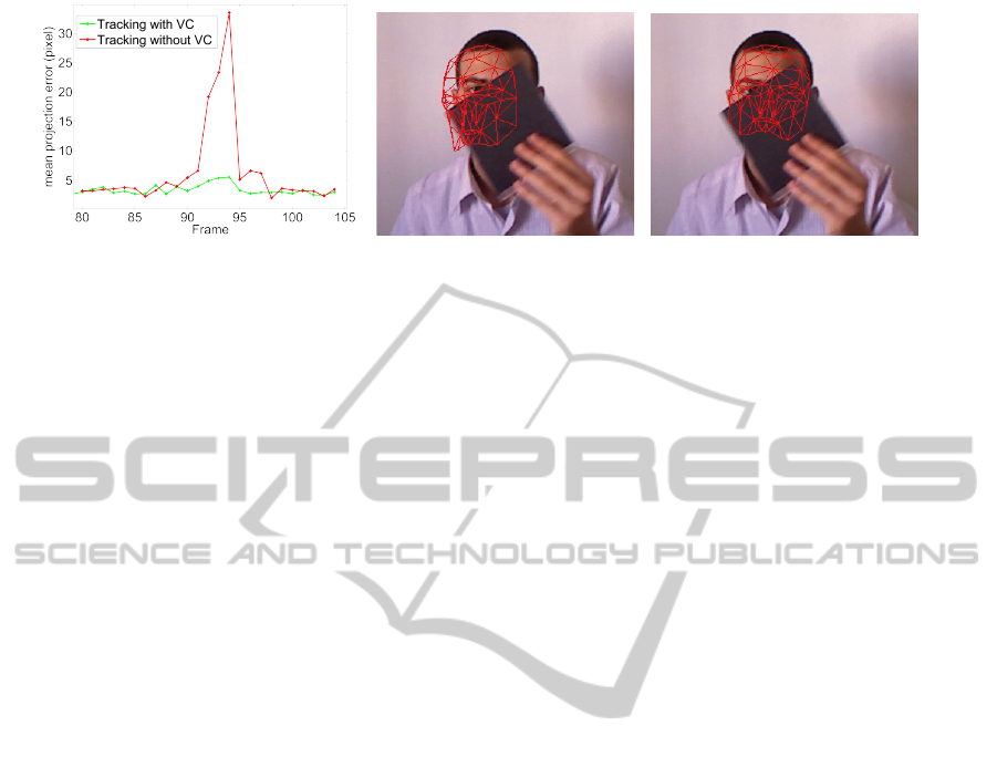
4.3 Visibility Constraint Importance
In addition to these evaluations, we demonstrate the
robustness of our method against partial occlusions.
The Biwi database doesn’t include this kind of situa-
tion. Thus, we acquire our own sequences in which
a person intentionally passes an object or his hand to
make a partial occlusion of his face. Then, we ap-
ply our tracking method twice: first with the visibility
constraint, second without visibility constraint. Fi-
nally, the evaluation is performed as follows. We have
manually labelled visible control points around the
eyes and the nose in every frame. Then, we computed
the average of the Euclidean distance between the la-
belled control points and the 2D projection of their
corresponding in the obtained 3D face model. Fig-
ure 3 shows the results of the tracking for a test data
sample. The evolution of these error measures along
the sequence is shown in Figure3(a). Even if this eval-
uation is done using 2D errors, we notice that the vis-
ibility constraint dramatically improves the quality of
out tracker in case of partial occlusions. Figures 3(b)
and 3(c) show the visual difference between the esti-
mated poses, respectively, with and without using the
visibility constraint.
5 CONCLUSIONS
This paper presents a new approach for 3D face pose
tracking using color and depth data from low-quality
RGB-D cameras. Our approach is based on the parti-
cle filter formalism. The particle evaluation model is
based on combining image and 3D data.
We have performed a quantitative evaluation of
the proposed method on the Biwi Kinect Head Pose
database, and we have demonstrated the impor-
tance of the interplay between the 3D and photo-
consistency energy computed to evaluate particles.
Future work, will extend our tracker to handle action
and expression deformation of the face.
Moreover, we intend to perform a GPU implemen-
tation of our method to evaluate simultaneously all
generated particles in each frame. Indeed, the actual
implementation of our method requires about 1 sec-
ond to estimate the face 3D pose for a new frame. The
GPU implementation can make the method faster and
we can rich a real time processing. The GPU imple-
mentation allows also to consider a larger number of
particles and to deal with more severe head displace-
ments.
3DFacePoseTrackingusingLowQualityDepthCameras
227
(a) (b) (c)
Figure 3: Tracking results in case of partial occlusions (occlusions occurred between frames 85 and 100). (a) Evolution of
the error along the sequence. (b) Visual result of the face pose estimation without visibility (VC) constraint for frame 94. (c)
Visual result of the face pose estimation using the visibility constraint for same frame. We notice a significant improvement
of the face pose estimation when the visibility constraint is used.
REFERENCES
Ahlberg, J. (2001). Candide-3 - an updated parameterised
face. Technical report.
Breitenstein, M. D., K
¨
uttel, D., Weise, T., Gool, L. J. V.,
and Pfister, H. (2008). Real-time face pose estimation
from single range images. In ”Proceedings of IEEE
Int. Conf. Computer Vision and Pattern Recognition,
pages 1–8.
Cai, Q., Gallup, D., Zhang, C., and Zhang, Z. (2010). 3d de-
formable face tracking with a commodity depth cam-
era. In European Conference on Computer Vision,
pages 229–242.
Fanelli, G., Weise, T., Gall, J., and Gool, L. V. (2011). Real
time head pose estimation from consumer depth cam-
eras. In Proceedings of the 33rd international confer-
ence on Pattern recognition, pages 101–110.
Kim, M., Kumar, S., Pavlovic, V., and Rowley, H. (2008).
Face tracking and recognition with visual constraints
in real-world videos. In ”Proceedings of IEEE
Int. Conf. Computer Vision and Pattern Recognition,
pages 1–8.
Lu, X. and Jain, A. K. (2006). Deformation modeling for
robust 3d face matching. In Proceedings of IEEE
Int. Conf. Computer Vision and Pattern Recognition,
pages 1377–1383.
Matsumoto, Y. and Zelinsky, A. (2000). An algorithm for
real-time stereo vision implementation of head pose
and gaze direction measurement. In International
Conference on Automatic Face and Gesture Recogni-
tion, pages 499–505.
Maurel, P., McGonigal, A., Keriven, R., and Chauvel, P.
(2008). 3D model fitting for facial expression anal-
ysis under uncontrolled imaging conditions. In Pat-
tern Recognition, 2008. ICPR 2008. 19th Interna-
tional Conference on, pages 1–4.
Morency, L.-P., Sundberg, P., and Darrell, T. (2003). Pose
estimation using 3d view-based eigenspaces. In In
Proceedings of the IEEE International Workshop on
Analysis and Modeling of Faces and Gestures, pages
45–52.
Ramey, A., Gonz
´
alez-Pacheco, V., and Salichs, M. A.
(2011). Integration of a low-cost rgb-d sensor in a
social robot for gesture recognition. In Proceedings
of the 6th international conference on Human-robot
interaction, pages 229–230.
Seemann, E., Nickel, K., and Stiefelhagen, R. (2004). Head
pose estimation using stereo vision for human-robot
interaction. In International Conference on Automatic
Face and Gesture Recognition, pages 626 – 631.
Valstar, M. F., Martinez, B., Binefa, X., and Pantic, M.
(2010). Facial point detection using boosted regres-
sion and graph models. In Proceedings of IEEE
Int. Conf. Computer Vision and Pattern Recognition,
pages 2729–2736.
Viola, M., Jones, M. J., and Viola, P. (2003). Fast multi-
view face detection. In Proc. of Computer Vision and
Pattern Recognition.
Weise, T., Bouaziz, S., Li, H., and Pauly, M. (2011). Real-
time performance-based facial animation. ACM SIG-
GRAPH 2011, 30(4):77:1–77:10.
Yang, R. and Zhang, Z. (2002). Model-based head pose
tracking with stereovision. In Automatic Face and
Gesture Recognition, pages 255–260.
VISAPP2013-InternationalConferenceonComputerVisionTheoryandApplications
228
