Hierarchical Roadmap Approach to Rough Terrain Motion Planning
Michael Brunner, Bernd Br
¨
uggemann and Dirk Schulz
Fraunhofer Institute for Communication, Information Processing and Ergonomics FKIE,
Wachtberg, Germany
Keywords:
Mobile Robot, Autonomy, Motion Planning, Rough Terrain, Active Actuators, Reconfigurable Chassis.
Abstract:
A reconfigurable chassis provides a mobile robot with a high degree of mobility and enables it to overcome
rough terrain in unstructured outdoor environments, like boulders or rubble, and challenging structures in
urban environments, like stairs or steps. Yet, many planning algorithms rarely exploit those enhanced capa-
bilities to the full extent, limiting these systems to mainly flat environments also traversable by less capable
fixed-chassis robots.
In this paper we introduce a two-stage roadmap approach to motion planning for reconfigurable robots which
utilizes the system’s actuators to traverse rough terrain and obstacles. First, by considering the platform’s op-
erating limits rather than the complete state, we quickly generate an initial path. Second, we refine the initial
path in rough areas within a constrained search space. So we are able to plan appropriate actuator configu-
rations to traverse rough areas and ensure the system’s safety. Our algorithm does not categorize the terrain
and does not use any predefined motion sequences. Hence, our planner can be applied to urban structures,
like stairs, as well as rough unstructured environments. We present simulation experiments to provide more
insight into our method and real-world experiments to prove the feasibility of our motion planning approach
on a real robot.
1 INTRODUCTION
Fixed-chassis robot platforms are commonly used to-
day. These platforms are limited to fairly flat areas as
their design prevents them from traversing structures
with high edges or steep inclinations. The challenges
they can overcome are directly related to the diame-
ter of their wheels or their track heights and to some
extend to their centers of mass.
In addition to commonly used fixed-chassis plat-
forms, there are systems with reconfigurable chassis.
Such a system is able to alter its state using actua-
tors to increase its traction, move its center of mass
to achieve a more stable state, or to lift itself over an
edge. This in turn enhances the mobility of the robot
and enables it to traverse a wide variety of environ-
ments which would be untraversable otherwise.
There exists a number of obstacles which are reg-
ularly encountered in robotic tasks. In urban en-
vironments single steps or stairs generally pose un-
traversable barriers for fixed-chassis robots, but can
be overcome by systems with reconfigurable drives.
In unstructured outdoor environments the shape of
obstacles is almost endless including, for instance,
coarse debris, rubble, rocks, or simply steep inclina-
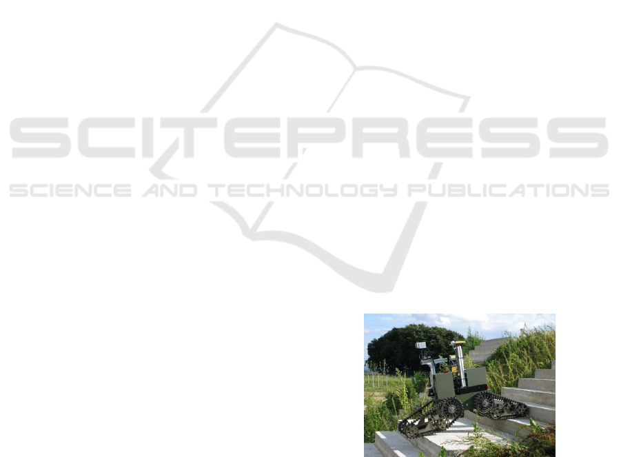
Figure 1: The Telemax robot is a tracked platform with four
actuators. It is able to traverse rougher terrain and to over-
come more obstacles than many fixed-chassis robots.
tions in hilly environments. In most cases usual robots
have to circumvent the structures as traversal is im-
possible or too risky.
To drive a mobile robot across the above men-
tioned structures is a challenging task even for a
trained operator. There are many aspects which have
to be considered when driving over obstacles. Most
of them can be neglected when navigating on flat ter-
rain. The stability of the robot is essential as the dan-
ger of falling over is greater on unstructured terrain.
Inertia and momentum will be increasingly important
if a robot is operated close to its limits. Moreover,
35
Brunner M., Brüggemann B. and Schulz D..
Hierarchical Roadmap Approach to Rough Terrain Motion Planning.
DOI: 10.5220/0004229000350046
In Proceedings of the 5th International Conference on Agents and Artificial Intelligence (ICAART-2013), pages 35-46
ISBN: 978-989-8565-38-9
Copyright
c
2013 SCITEPRESS (Science and Technology Publications, Lda.)

varying contact points of the mobile system change
its behavior to actuator and driving commands.
We developed a hierarchical roadmap approach
to motion planning for reconfigurable robots. First,
we generate an approximate solution and refine it
in a subsequent phase. The refinement concentrates
on path segments in rough regions and accounts for
the actuators and the robot’s stability and traction.
Since the algorithm does not need a previous ter-
rain/structure classification and does not use any pre-
defined motion sequences, it can be applied to rough
outdoor environments as well as obstacles in urban
surroundings.
The remainder of this paper is organized as fol-
lows: section 2 names related work in this area of
research. Section 3 gives a short overview of our
method and names differences to related works. In
section 4 we introduce the roughness quantification
used. Sections 5 and 6 describe the preliminary plan-
ning and the detailed motion planning phases, respec-
tively. In section 7 we discuss the parameters and
guidelines on how to set them. Experiments are pro-
vided in section 8, and we conclude in 9.
2 RELATED WORK
This section focuses on common approaches to rough
terrain path planning and on previous work using
methods similar to ours, i.e. hierarchical methods,
methods employing a graph-search and algorithms for
tracked robots.
Many algorithms for traversing rough terrain or
climbing structures, like stairs, involve a preceding
classification step (e.g. using line detection to identify
stairs). This information is used to steer the system
during climbing, fixing its heading to the gradient of
the staircase (Mourikis et al., 2007; ?). In (Dornhege
and Kleiner, 2007) a two dimensional A*-search on
behaviour maps is used to find paths in rough environ-
ments for a tracked robot, similar to our model. The
path represents a sequence of predefined skills en-
coded in the behavior maps. Fuzzy rules and Markov
random fields are used to classify the environment and
facilitate skill selection. A comprehensive approach
to traverse rough outdoor terrain as well as stairs is
presented in (Rusu et al., 2009). The framework in-
cludes a mapping component, a terrain classification
and a two-phase planning algorithm. A high-level
planner samples a transition graph across different ter-
rain types and provides an initial path. In the second
phase specialized terrain sub-planners refine the path
and return gait primitives for a RHex robot (e.g. stair-
climbing gait primitives). The approaches above are
limited to the set of terrain types or structures which
are imposed by their classification scheme or the set
of motion sequences. On the contrary, our algorithm
does not rely on such a terrain/structure classification
or on a set of motion sequences. Hence, it can be ap-
plied to a range of different environments.
We utilize a two-phase planning method which
produces an initial approximate solution followed
by a refinement of the initial result. As in (Rusu
et al., 2009), other works also use a similar approach.
Kalakrishnan and colleagues introduced a controller
for fast quadruped locomotion over rough terrain
(Kalakrishnan et al., 2010). The controller decom-
poses the controlling task into several sub-tasks; first,
they generate a terrain reward map using a learned
foothold ranking function and then produce an ap-
proximate path. In subsequent steps this first so-
lution is improved to ensure kinematic reachability
and a smooth and collision-free trajectory. Like our
method, this is a multi-phase algorithm which re-
quires a map and implements a terrain analysis. How-
ever, our terrain analysis relies on a roughness quan-
tification similar to (Molino et al., 2007) instead of
a ranking function of the actuator contacts. On the
contrary, the authors of (Kalakrishnan et al., 2010)
propose a reactive controller to traverse rough terrain
rather than a planning algorithm. Also the terrain in-
teraction of tracked robots is quite distinct compared
to the interaction of their legged robot.
Further, path refinement can also be achieved by
path optimizing methods. CHOMP (Ratliff et al.,
2009) is an optimization method for continuous tra-
jectories using covariant gradient descent. It can op-
timize a path over a variety of criteria. Since it is ap-
plicable to unfeasible paths, it can be used as a stan-
dalone motion planner. STOMP (Kalakrishnan et al.,
2011) is a stochastic path optimizer using a path in-
tegral approach which does not require any gradient
information like CHOMP. Therefore, it can overcome
local minima and more general costs are applicable.
The major drawback of both methods is the limita-
tion to trajectories of a predefined fixed length. This
makes them inapplicable to our problem.
In this work we present a roadmap algorithm for
rough terrain path planning. Roadmap methods are
commonly applied to this problem in the literature.
An Anytime A*-search is used to find paths in a multi-
resolution 4D state lattice for indoor environments
(Rufli et al., 2009). The resolution of the lattice is
adjusted with respect to terrain or task characteristics
(e.g. narrow passages and goal proximity). The on-
line navigation utilizes a precomputation step which
determines paths for constrained areas. In (Miro et al.,
2010) the Fast Marching Method (FMM), a breadth-
ICAART2013-InternationalConferenceonAgentsandArtificialIntelligence
36
first search algorithm, is used on a 3D lattice to plan
stable paths for actively reconfigurable robots. The
system’s stability guides the search on a triangular
mesh of the environment. The actuators of the Pack-
bot robot used in this research are actively controlled
like the actuators of our Telemax platform.
The authors of (Hait et al., 2002) present an
approach to motion planning on rough terrain for
a wheeled robot with passive suspension using an
A*-search on a discretized configuration space with
heuristics to limit the search space. The algorithm
considers the robot’s stability, mechanical limits, col-
lisions with the ground, and uncertainties on the ter-
rain model and the robot position. While they also
use a graph-search and measure the robot’s stability,
their algorithm does not have to account for actuators
due to the robot’s passive suspension. In contrast, we
must include the actively controlled actuators during
planning.
Magid et al. developed a rough terrain plan-
ning algorithm for a tracked robot with four actively
controlled crawlers (Magid et al., 2011). They use
a graph-search to find motion sequences in a dis-
cretizied state space which also allows for motions
of controlled balance losing (e.g. insignificant falls
from small edges). However, rather than autonomous
navigation their application is to reduce the burden on
operators of search and rescue missions by propos-
ing paths through rough terrain. Unlike us, they
categorize the states to distinguish between different
transition types and consider controlled balance los-
ing states. However, they also plan on a discrete
state space and use a robot with actively controlled
crawlers, similar to our model.
3 OVERVIEW AND
DISCRIMINATORS
We start with a short overview of our algorithm. We
employ a hierarchical roadmap algorithm for motion
planning of actively reconfigurable robots in rough
environments. Although we developed our algorithm
for a tracked robot model, it is likely to be usable
for other articulated robot models with similar loco-
motion (e.g. wheeled platforms). Given a map we
compute the roughness of the environment (section
4). In the preliminary planning phase we build a mo-
tion graph according to the robot’s operating limits
and perform a graph-search to find an initial path (sec-
tion 5). During the detailed motion planning step we
refine the initial path in rough areas only. To this end,
we first identify the path segments leading through
rough terrain. In flat areas we do not perform a de-
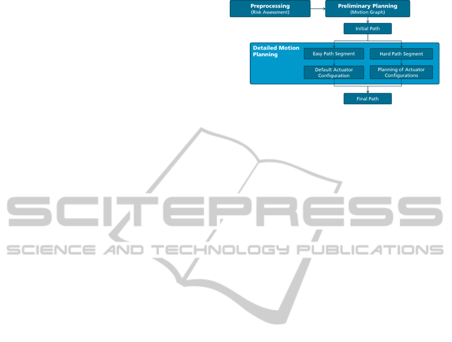
Figure 2: Algorithm overview: First, a preprocessing step
analyzes the environment, followed by a preliminary plan-
ning step to find an initial path and a detailed motion plan-
ning step which refines the preliminary solution in rough
areas using the actuators. In flat areas, a default configura-
tion is applied.
tailed planning and apply default configurations in-
stead. We construct a state graph considering the ac-
tuators for a tube-like area around each rough path
segment. Using a graph-search we find sequences of
robot states including the actuators (section 6). Con-
sult figure 2 for a scheme of our algorithm.
Our algorithm applies to tracked reconfigurable
robots like ours (see figure 1), but not to systems
with legged locomotion since the robot-terrain inter-
actions are very distinct. However, parts may be used
across different locomotion models, e.g. the rough-
ness quantification and some of the metrics. Further,
looking at a complete robot system, we consider our
method to be the global planning component which
provides a plan followed by a feedback controller
which takes care of the plan execution using sensor
data for localization and obstacle avoidance in poten-
tially dynamic environments. Such a controller is be-
yond the scope of this paper.
In the following we state how our approach differs
from other approaches. First, we distinguish between
flat and rough regions but do not rely on a previous
terrain classification or on motion sequences a priori
designed to overcome specific challenges. Therefore,
we are not limited to a previously defined set of terrain
classes or a set of motion sequences. However, our
contact points algorithm depends on a least-squares
plane approximation of the terrain (similar to (Magid
et al., 2008)), which works reasonably well on gen-
erally continuous surfaces, but not on discontinuous
environments. Nevertheless, our algorithm can be ap-
plied to traverse rough outdoor environments as well
as to overcome challenging structures in urban sur-
roundings.
Second, rather than taking the entire preliminary
path to guide the second detailed motion planning,
we solely consider path segments which lead through
rough areas. Since a detailed motion planning is not
necessary for path segments on flat regions, planning
HierarchicalRoadmapApproachtoRoughTerrainMotionPlanning
37

can be significantly simplified. Thus, we are able to
speed up planning.
Further, we use simpler robot and terrain mod-
els compared to planetary rover path planning ap-
proaches. They often utilize detailed dynamic and
mechanic models to capture the robot-terrain interac-
tion in depth (Howard and Kelly, 2007). Such models
are not always obtained easily and, thus, not necessar-
ily available for a specific robot model.
4 MAP AND TERRAIN
ROUGHNESS
Whether a given structure is traversable or not cannot
be determined easily. In 2D navigation this is usu-
ally addressed with a simple threshold on the height
differences; everything above this threshold is un-
traversable. For rough terrain and structures this ques-
tion becomes very hard to answer. While for 2D nav-
igation a 2D laser range finder is sufficient to gather
the necessary information about the surroundings, a
3D sensor is often not enough to navigate through
rough environments due to the still limited sensor
coverage.
There are several reasons why it seems to be ex-
tremely difficult to reliably decide on the traversabil-
ity of a structure and rough terrain based on local sen-
sor information solely. First, the dimensions of rough
terrain areas or challenging structures usually exceed
the sensor range; second, some sections of the envi-
ronment are often occluded; third, the limiting nar-
row view of sensors mounted on a mobile robot makes
it difficult to get a sufficient overview; finally, while
traversing rough terrain the robot’s state often orients
the sensors such that they are unable to cover the en-
vironment. For example, consider a flight of stairs;
the very narrow view makes it hard to recognize the
stairs especially all the way to the top. While on the
stairs and close to the top the sensors cover very little
of the ground.
Additionally, the robotic system is exposed to un-
necessary risk if it starts to traverse an area which
turns out to be ultimately untraversable. A map allows
to decide whether an area is likely to be traversable
(without considering traction) and to assess the risk of
a path and whether driving through a hazardous area
is worth the risk or circumventing the region with rea-
sonable additional costs is more appropriate.
On the other side, the validity of the planning is
closely related to the level of detail of the map. Large
detailed maps are rarely available. This may be solved
by a coarse map with detailed patches for rough re-
gions. For our research, we use a map of the environ-
ment to avoid the complex perceptual task of 3D nav-
igation in rough terrain. This simplifies the percep-
tual component and allows us to focus on the motion
planning aspect of this problem (Kalakrishnan et al.,
2010).
4.1 Risk Distribution
In our approach we use a heightmap to represent the
environment because it is simple to use and sufficient
for our application. In order to assess the difficulty
of a position within the map, we use techniques from
image processing to compute a roughness quantifica-
tion. First, we apply a maximum filter with a window
w
x,y
of size x × y to the height differences. A dis-
tortion of the range of values can be prevented by a
threshold h
max
which conveniently can be set to the
robot’s maximal traversable height. The threshold is
also used to scale the values to [0, 1]. Subsequently,
we apply a two dimensional Gaussian blur to smooth
the transitions. The maximum filter prevents isolated
peaks to be smoothed by the Gaussian filter. Figure 3
shows an example of the roughness quantification.
Using an appropriate kernel size allows us to vir-
tually inflate hazardous areas. This is commonly done
in 2D navigation to keep the robot away from obsta-
cles. In contrast, our high risk areas are avoided by the
robot, but if required, will not prohibit traversal. An-
other benefit is the simple and highly parallelizable
computation.
We use this roughness quantification in both the
preliminary planning as well as the detailed motion
planning to adjust the planning according to the diffi-
culty of the environment.
5 PRELIMINARY PLANNING
Driving with actively reconfigurable robots on rough
terrain introduces a large planning space. Addition-
ally, aspects of the robot state, like the stability, are
not naturally satisfied and must be tested. The robot’s
actuators must be incorporated into the planning pro-
cess and the quality of the path must be judged not
only by its length, but also by the robot’s stability
and traction as well as the time required for transla-
tion, rotation and for actuator movements. First, we
employ a preliminary path search to quickly find an
environment-driven path to the goal location. Subse-
quently, the path is used to constrain the search space
for the detailed planning. The detailed planning phase
determines the final path consisting of the robot con-
figurations including the actuators.
ICAART2013-InternationalConferenceonAgentsandArtificialIntelligence
38
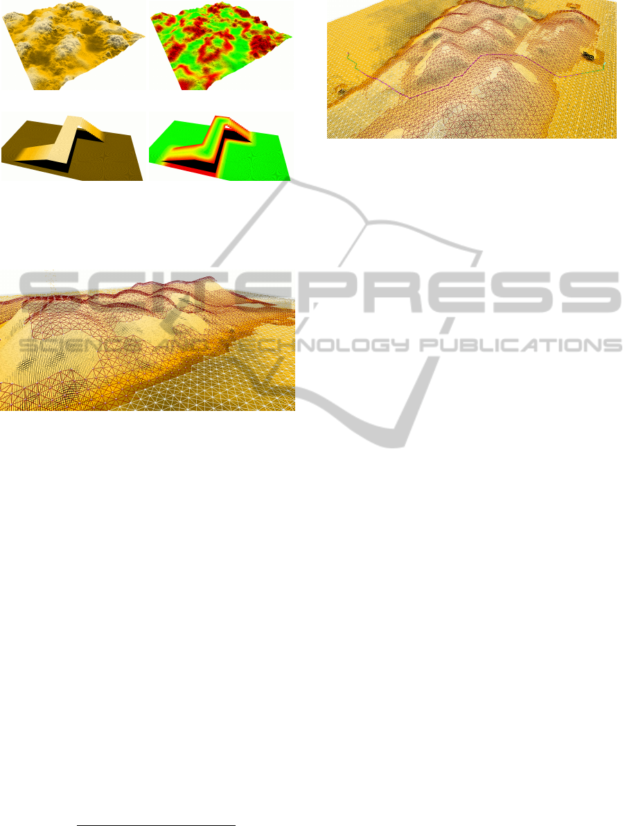
Figure 3: Two maps (left) and the corresponding roughness
quantifications (right); The risk value associated with a re-
gion is based on the height differences in this area. The
colors indicate the degree of roughness, ranging from green
for flat regions over yellow to red, high risk areas.
Figure 4: The motion graph encodes the traversability of
the terrain. Areas with low height differences are white and
those with higher differences are red.
The preliminary planning utilizes the previously
discussed roughness quantification to force the robot
to avoid hazardous areas and to prefer less risky
routes. In flat regions the consideration of the com-
plete state is not necessary, whereas it is essential in
rough regions to increase the robot’s safety and en-
sure successful traversal. At the beginning we do not
know through which parts of the environment the path
will lead and if considering the complete state is re-
ally necessary. Therefore, we use the utmost operat-
ing limit of the mobile base setting the actuators aside.
The maximal traversable height of the robot consti-
tutes the operating limit. This way we obtain the least
restrictive limit. We build a motion graph which rep-
resents the ability of the mobile robot to traverse the
environment. The motion graph is based on the op-
erating limits of the robot. The transition costs are
given by the time t required to traverse a graph edge
e. Hereby, we reduce the permissible velocity accord-
ing to the terrain roughness:
t =
d
max
v
min
, (1 −w
p
· r) · v
max
,
where d is the length of edge e and r the maximal
Figure 5: The motion graph and the initial path split into
segments. Path segments through flat regions are green;
segments through rough regions are purple.
risk of the vertices of e from the roughnes quantifi-
cation. v
min
and v
max
are the minimal velocity the
robot should drive in high risk areas and the robot’s
maximal velocity, respectively. A safety weight w
p
allows the adjustment of the importance of safety.
Low safety weights diminish the influence of the risk,
hence lead to possibly shorter, but riskier paths. On
the contrary, high values increasingly force the robot
to take low risk paths. With those edge weights we
find a path performing a usual graph-search, e.g. A*-
search or Dijkstra-search. Please refer to (Brunner
et al., 2012) for a more detailed description of the
metrics used by our algorithm.
While constructing the motion graph, we distin-
guish between areas of convenient risk levels (cor-
responding to moderate height differences) and re-
gions with higher risks (corresponding to challenging
height differences). See figure 4 for an example. We
use this distinction in the second planning phase to
split up the initial path into easy and hard segments
and to determine whether a detailed planning of the
robot motions is necessary.
6 DETAILED PLANNING
Rough terrain is more challenging and exposes the
mobile robot to a greater risk than flat environments.
Therefore, we have to refine the preliminary path in
rough areas using the complete robot states. The state
of a reconfigurable robot may look like
(x, y, z, θ, ψ, φ, v, ω, ˙v,
˙
ω, a
1
, . . . , a
n
),
where the first part describes the 6D pose of the robot.
The translational and rotational velocities are v and
ω, and the corresponding accelerations are depicted
by ˙v and
˙
ω. a
i
are the control values of n actuators.
Reducing the state to the controllable part leads to
(x, y, θ, v, ω, ˙v,
˙
ω, a
1
, . . . , a
n
).
HierarchicalRoadmapApproachtoRoughTerrainMotionPlanning
39

Figure 6: A tube around a rough segment (purple). The tube
is used to restrict the search space of the second planning
step.
The controllable parts still lead to a large in-
tractable search space. Therefore, we use the pre-
liminary path to constrain the robot’s state space for
the second planning phase. First, we split the path
into segments leading through flat areas with low
risks and segments through rough regions with high
risk levels (see figure 5). For flat segments the sta-
bility of the robot system can be safely assumed as
done in 2D navigation. Further, any robot configura-
tion may be applied with no or little risk. This way,
we avoid unnecessary planning in a high dimensional
space for easily accessible parts of the environment
and speed up planning. However, rough regions re-
quire an additional planning of the robot’s actuators to
ensure safety and task completion. We constrain the
state space further through focusing the refinement on
tube-like areas around rough path segments (see fig-
ure 6). This concentrates the search on the promising
region and makes the search feasible.
The detailed motion planning accounts for the en-
vironmental risk, the system’s stability and its trac-
tion, and for the time consumed by translation, rota-
tion and actuator movements. Since the robot’s speed
is very low when traversing hazardous areas, we put
forces and dynamic stability aside. To quantify the
stability and the traction we approximate the robot’s
footprint by the best fitting plane (Magid et al., 2008).
This limits the current approach to mainly continuous
environments (e.g. hills, stairs, ramps, etc.).
The state graph models a discrete configuration
space including the actuators. The edge weights are
defined by a more accurate cost function which con-
siders more aspects of the robot state compared to the
preliminary planning. The cost c of an edge in the
graph breaks down into a safety part c
safety
and a time
part c
time
:
c = w · c
safety
+ (1 − w) · c
time
.
To quantify the safety, we examine the stability of
the robot S using a stability margin and the center of
mass, the traction T by considering the actuator an-
gles to the surface and the environmental risk r from
the roughness quantification. We take the maximal
corresponding values of the involved vertices.
c
safety
=
r +
1
2
(S + T )
2
.
The time term includes the time required for transla-
tion t
v
and rotation t
ω
as well as for actuator move-
ments t
a
. We use a triangle inequality to favor simul-
taneous execution.
c
time
=
t
2
v
+t
2
ω
+(1−w·c
safety
)
2
·t
2
a
t
v
+t
ω
+(1−w·c
safety
)·t
a
.
Moving the actuators needs time, but does not result
in spatial gain. Therefore, the time is a more appro-
priate measure than a distance measure. If the robot
is in an unsafe state (small values of c
safety
), we will
reduce the costs of actuator movements to enable the
robot to improve its state with small costs. A safety
weight w allows to adjust the robots behavior, result-
ing in faster paths with less actuator movements or
safer configurations through better suited actuator po-
sitions. However, adjusting the actuators to the cur-
rent situation requires more time, which increases the
execution time of the path. A detailed description of
the cost function and the different measures involved
can be found in (Brunner et al., 2012).
Using a graph-based model with the above men-
tioned costs allows us to perform a usual graph-
search, e.g. A*-search or Dijkstra-search, on the state
graph to find the most stable and most efficient path
to the goal. In contrast to the first planning phase,
this path consists of complete robot states. If several
rough path segments exist, the path planning can be
parallelized.
The detailed motion planning can fail to find a
valid path because the simplification of the prelim-
inary planning discards several aspects of the robot
state, like the orientation and the actuators. In this
case, the preliminary planning must be triggered to
produce another path using a different safety weight
(see sections 7 and 8.1 for more information).
7 PARAMETER SETTINGS
The purpose of this section is to name the parameters
of our method and to give guidelines for appropriate
values. First of all, many of the quantities used in
our method are determined by the robot model or our
setup, e.g. the maximal traversable height or the max-
imal velocity.
The kernel size of the filters employed in the
preprocessing step to calculate the roughness values
should be the diagonal of the robot dimensions. So a
ICAART2013-InternationalConferenceonAgentsandArtificialIntelligence
40
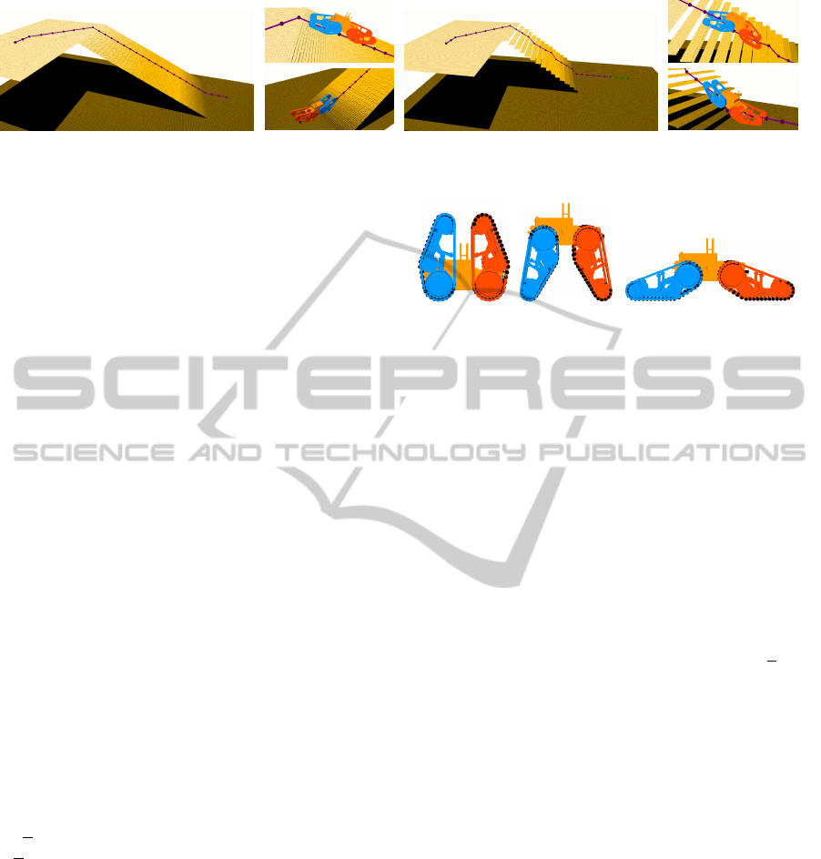
(a) A ramp. (b) A steep flight of stairs.
Figure 7: The images show simulation environments posing different challenges and the robot during execution.
cell’s risk value considers the area of the robot’s foot-
print if it is placed at the same cell. As the robot di-
mensions change with the actuator configurations we
used the average of the smallest and largest configu-
ration, i.e. 100 cm for a squared window.
We consistently set the resolution of our maps to
5cm. The resolution of the motion graph should be set
such that the diagonal edges are shorter than the robot
length. Using half the robot size, we do not need any
validity tests between robot positions (i.e. vertices)
as the tests at the robot positions cover the transition
edges between them. To distinguish between flat ar-
eas and rough areas we specify the maximal height
which can be traversed using a 2D navigation scheme
which does not use the actuators. We set the value
to 9 cm considering the robot’s capabilities using the
default actuator configuration.
The size of the tube around rough segments deter-
mines the state space expansion for the detailed mo-
tion planning. We required all positions to be less
than 75 cm away from the path. Hence, we include
all positions (vertices) which need at most two edges
to reach the path provided a graph resolution of 30 cm
(half the Telemax length). We found including two
positions to either side of the path in the tube as a rea-
sonable trade-off between the state space expansion
and planning time.
The minimal velocity v
min
used in the cost terms
for the translation time specifies the velocity the robot
should drive in the riskiest areas. We set the value to
0.12
m
s
, i.e. 10% of the robot’s maximal velocity of
1.2
m
s
.
The two safety weights w
p
for the preliminary
planning and w for the detailed motion planning allow
to adjust the importance of the safety for the planning
queries. The former will influence the major direction
of the path as it determines the initial path. The later
influences the robot configurations and the actuators.
Appropriate values depend on the application and the
robot model. However, we used values of w
p
= 0.75
and w = 0.5 in our experiments. Section 8.1 discusses
the effect of different values for w
p
and w.
(a) (b) (c)
Figure 8: Telemax actuator configurations: (a) completely
folded (all actuators at −90
◦
), (b) completely expanded (all
actuators at 80
◦
) and (c) maximal ground contact (all actu-
ators at 15
◦
).
8 EXPERIMENTAL RESULTS
We use a Telerob Telemax robot model in our re-
search, see figure 1. The robot is 60cm long, 40 cm
wide and weighs about 70 kg. It has four tracks which
can be rotated 170
◦
from entirely folded (−90
◦
) all
the way down (80
◦
) lifting the robot about 45 cm up
(see figure 8). Completely stretched the robot has a
length of 120 cm. The robot is equipped with a skid-
drive, and its maximal translational speed is 1.2
m
s
.
We present simulation experiments to illustrate
the effects of different safety weights on both plan-
ning phases. We also analyze the benefit of the state
space restriction using the initial path. Further, we
describe two experiments with our Telemax robot in
real-world scenarios. They show that the plans of our
motion planner are feasible and can be executed by
our robot. We implemented a simple controller which
will adjust the actuators if they differ from the current
target angle, then rotates to the current target orienta-
tion, and finally drives. Its localization is solely based
on differential GPS.
8.1 Safety Weights
The safety weight of the preliminary planning phase
determines the major direction of the path as subse-
quent route corrections are limited to the tubes around
the rough segments. We performed several planning
queries with different safety weights keeping start and
goal location the same (figure 9). We increased the
safety weight w
p
from 0.0 to 1.0 with increments of
HierarchicalRoadmapApproachtoRoughTerrainMotionPlanning
41
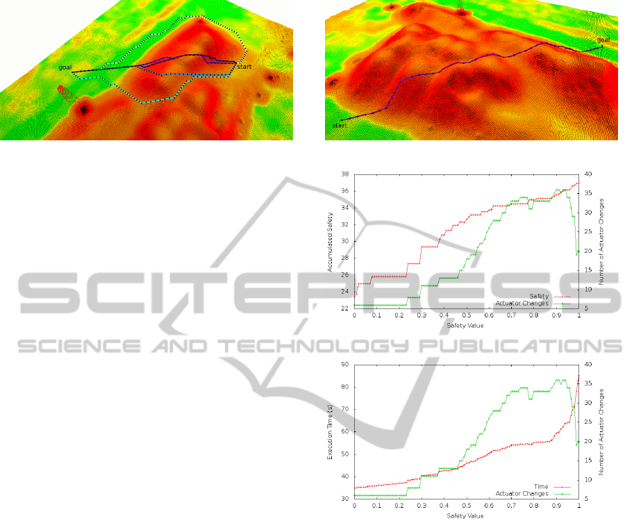
Figure 9: Influence of the safety weight on the preliminary
path planning. The image shows five paths with different
safety weights w
p
∈ {0.0, 0.25, 0.5, 0.75, 1.0}. The higher
the safety weight, the lighter is the coloring of the path. The
map is colored according to the risk values.
0.25. Disregarding safety completely (w
p
= 0.0) leads
to a straight path within the motion graph. Increasing
the value to 0.25 changes the path slightly, crossing
some of the high risk areas directly with the inclina-
tion. This reduces the time spend in those regions and
increases the safety by reducing the system’s roll an-
gle. At w
p
= 0.5 the path avoids the first high risk
region and crosses the second straight. Further incre-
mentation (w
p
= 0.75) forces the path to follow the
dig in the middle of the hill and to circumvent the high
risk areas. Finally, with a value of w
p
= 1.0 the path
leads through the low risk regions around the hill.
Summarizing, as desirable for different missions,
the safety weight w
p
significantly influences the direc-
tion of the path. A value around w
p
= 0.75 provides a
reasonable trade-off between safety and path length.
The safety weight of the second planning phase
mainly influences the choice of actuator configura-
tions; higher values will result in safer states at each
path position. To achieve a common basis for the
comparison, we selected an initial path, held it con-
stant for all second phase planning queries and shrunk
the tube to solely include the initial path (figure 10
top). Hence, we prevented impacts of different initial
paths and of route corrections within the tube during
the second planning phase. This also fixes the number
of translations and rotations leaving only the actuator
configurations to be determined.
The middel image of figure 10 shows the accumu-
lated safety (inverted safety cost c
safety
) of the state
space paths plotted against the safety weight. Also on
the second y-axis we plotted the number of actuator
changes since they are the reason for the increasing
safety. Raising the safety weight leads to more actu-
ator adjustments in order to reach better suited robot
states in every position. Ultimately, this increases the
total safety of the final path. Even though the actu-
ator changes decrease for higher safety weights, the
path safety still rises. This is explained by longer
sequences of stable configurations rendering changes
(a)
(b)
(c)
Figure 10: Influence of the safety weight on the detailed
motion planning: The path used for evaluation is shown on
top. We fixed the initial path and reduced the tube to the
initial path, leaving only the actuator configurations muta-
ble. The curves show the total safety (inverted safety cost
c
safety
) and the execution time (seconds) of the final state
space paths for different weights. As only the actuator con-
figurations are mutable, we include the number of configu-
ration changes on the second y-axis to illustrate their corre-
lation. The decrease in actuator changes for higher values
of w is due to long sequences of the same actuator configu-
ration. The increasing execution time for those values of w
are caused by higher rotation times in stable and high trac-
tion configurations.
unnecessary.
Similar, the bottom image of figure 10 displays
the execution time of the state space paths using dif-
ferent safety weights. The higher number of state
corrections through actuator adjustments results in a
higher execution time comprising the time required
for the adjustments. The execution time more than
ICAART2013-InternationalConferenceonAgentsandArtificialIntelligence
42
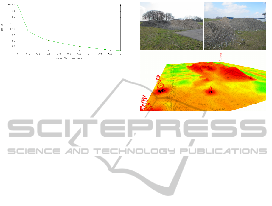
Figure 11: The effect the path segmentation into flat and
rough segments has on the planning time. The y-axis is in
log-scale. The plot shows the mean ratios between the plan-
ning times without path segmentation and with path seg-
mentation for paths with different portions of roughness.
We performed 100 for each portion; 50 without path seg-
mentation and 50 with path segmentation.
doubles from about 35 s at w = 0.0 to roughly 85 s at
w = 1.0. The still growing execution time for falling
actuator changes towards higher values of w is caused
by lower rotational velocities of more stable config-
urations with higher traction. The rotational velocity
of reconfigurable robots depends on its actuator con-
figuration. For example, consider the Telemax robot.
If the flippers are completely stretched, the robot will
be 120 cm long with maximal ground contact. In this
configuration rotation takes considerable longer than
with all flippers folded.
Ultimately, the planning of the actuator positions
is essential to increase the safety of the robotic system
during rough terrain traversal. This leads to a signif-
icant increase of the path’s execution time due to the
time needed for the actuator adjustments and the in-
creased duration of rotational maneuvers.
8.2 Restriction of the State Space
This section discusses the restriction of the state space
of the detailed motion planning. We constrain the
state space using the preliminary path. As a detailed
assessment of the robot state is unnecessary in flat ar-
eas, we consider only segments of the path which lead
through rough regions. This allows us to handle larger
planning queries as we focus on a subset of the state
space. Also, this significantly reduces the planning
time.
The size of the state graph in the second plan-
ning phase depends on the chosen discretization, the
tube size and the length of the rough segments. If we
plan without a preliminary path constraining the state
space, the graph size depends on the size of the map
(if Dijkstra-search is used) or the roughness and the
distance to the goal (if a A*-search is used). Depend-
ing on these factors, our roadmap method will run out
of memory before returning a valid path.
Figure 12: The first real-world scenario: Two pictures of
the hill of rubble and the the map of size 36.4 × 30.45 m
captured with a laser range finder.
Additionally to using just the initial path, we con-
centrate the path refinement during the second plan-
ning phase on the path segments which pass through
rough areas. We generated several paths with differ-
ent portions of flat and rough areas, ranging from 0%
to 100% in steps of 10%. We then performed 100
queries for each portion; 50 queries without splitting
the path into flat and rough segments, i.e. consider-
ing the entire path to be rough, and 50 queries us-
ing the segments to plan only the rough portion in de-
tail. Figure 11 shows the mean values of the ratio be-
tween planning times without path segmentation and
with segmentation. The curve indicates that planning
the flat path segments in detail increases the planning
time considerable. If more than one rough segment
exist, the second phase planning can be parallelized.
The planning queries of the real-world experiments
(see figures 13 and 16) have rough segment rates of
0.65 and 0.5, i.e. about 1.5 times faster and twice as
fast, respectively.
8.3 Real-world Experiments
We also performed tests with a real robot, the Telerob
Telemax model. The environments are shown in fig-
ures 12 and 15. Both maps were recorded using a
laser range finder and were subsequently filled and
smoothed to facilitate planning. Their sizes are 36.4×
30.45m and 43.95 × 32.95 m, respectively. These are
quite large environments compared to related works
which usually focus on smaller patches of purely
rough terrain. For the tests we used the following
values: The resolution of the maps was 0.05m and
0.3m (half the robot length) for the motion graphs.
HierarchicalRoadmapApproachtoRoughTerrainMotionPlanning
43

Figure 13: Results of the first real-world experiment: The
top image shows the path followed by images of the robot
during the execution.
Figure 14: The actuator joint values of the path in the first
real-world scenario on the hill of rubble. Values below zero
indicate folded configurations and values greater zero cor-
respond to expanded configurations.
We considered eight orientations in each position (45
◦
steps). The actuator values were bound to [−45
◦
, 45
◦
]
in steps of 15
◦
since more folded (smaller −45
◦
) or
more expanded (greater 45
◦
) configurations provide
little more benefit. Further, both front, respectively
both rear actuators were required to be the same. The
safety weights were set to w
p
= 0.75 and w = 0.5. We
chose a folded configuration with all actuator values
equal to −45
◦
as default configuration. The default
configuration was applied in flat areas. The maxi-
mal ground contact is reached with all actuators at 15
◦
(see figure 8).
Figure 15: The second real-world scenario: Two pictures
of our testing hill and the the map of size 43.95 × 32.95 m
captured with a laser range finder.
We performed several planning queries of which
we present two, one for each map. Figures 13 and
16 show the planning queries and pictures of the ex-
ecution by our robot. In the first scenario (figure 13)
the robot had to cross the hill of rubble through the
low risk areas, avoiding high elevations. The robot
was able to follow the proposed path while falling
over was prevented by the changing actuator configu-
rations (figure 14). The robot slipped casually due to
the small-grained material of the rubble.
Equally, the hill of the second scenario was tra-
versed by our robot given the plan shown in figure
16. The robot climbed the steep ramp with the most
stable configuration, returned to the default setting on
the flat top of the hill and adjusted the actuators anew
for the descent (see figure 17 for the actuator values).
The localization which was solely based on differen-
tial GPS, and the map’s noise caused some difficulties
for the controller when determining which part of the
plan should be executed.
However, in general, the robot was able to exe-
cute all plans of our motion planning algorithm and
successfully traversed the rough terrain. Further, the
proposed configurations proved to be suited to ensure
the safety of the robot. Problems during the execution
were related to terrain parameters (the small-grained
rubble) or to inaccuracy of the sensor data (the map
and the localization with differential GPS).
9 CONCLUSIONS AND FUTURE
WORK
In this paper we presented a motion planning algo-
rithm for robots with actively reconfigurable chassis
ICAART2013-InternationalConferenceonAgentsandArtificialIntelligence
44
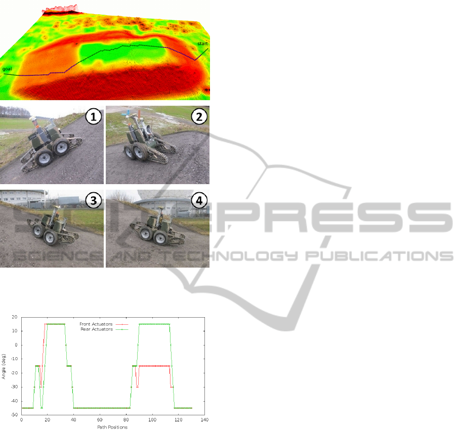
Figure 16: Results of the second real-world experiment:
The top image shows the planned path followed by images
of the robot during the execution.
Figure 17: The actuator joint values of the path in the sec-
ond real-world scenario on the testing hill. Values below
zero indicate folded configurations and values greater zero
correspond to expanded configurations.
to find safe paths through rough terrain. We intro-
duced a hierarchical roadmap planner which quickly
determines a preliminary path considering the robot’s
operating limits rather than the complete states. The
initial path is used to constrain the high dimensional
state space of the second detailed motion planning
phase. We plan the robot’s motions in detail only in
rough areas where it is really necessary. Our algo-
rithm does not rely on predefined motion sequences
or on a terrain classification. Hence, it can be applied
to urban structures, like stairs, as well as to rough un-
structured environments.
Future work will focus on overcoming more chal-
lenging obstacles, like boxes or high steps. This will
require a more accurate modeling of the robots foot-
print and the contact points with the environment.
Also, we will investigate using optimal sampling-
based methods for continuous motion planning in the
second phase. The current controller is solely based
on differential GPS; we are planning to improve our
path execution through a better localization.
REFERENCES
Brunner, M., Brueggemann, B., and Schulz, D. (2012). Au-
tonomously Traversing Obstacles: Metrics for Path
Planning of Reconfigurable Robots on Rough Terrain.
In Int. Conf. on Informatics in Control, Automation
and Robotics. Best Paper Award.
Dornhege, C. and Kleiner, A. (2007). Behavior maps for
online planning of obstacle negotiation and climbing
on rough terrain. In IEEE/RSJ Int. Conf. Intell. Robots
Syst.
Hait, A., Simeon, T., and Taix, M. (2002). Algorithms
for Rough Terrain Trajectory Planning. Advanced
Robotics, 16:673–699.
Howard, T. M. and Kelly, A. (2007). Optimal Rough Terrain
Trajectory Generation for Wheeled Mobile Robots.
Int. J. Robot. Res., 26(2):141–166.
Kalakrishnan, M., Buchli, J., Pastor, P., Mistry, M., and
Schaal, S. (2010). Learning, Planning, and Control
for Quadruped Locomotion over Challenging Terrain.
Int. J. Robot. Res., 30:236–258.
Kalakrishnan, M., Chitta, S., Theodorou, E., Pastor, P., and
Schaal, S. (2011). STOMP: Stochastic Trajectory Op-
timization for Motion Planning. In Int. Conf. Robot.
Autom.
Magid, E., Ozawa, K., Tsubouchi, T., Koyanagi, E., and
Yoshida, T. (2008). Rescue Robot Navigation: Static
Stability Estimation in Random Step Environment.
LNCS - Simulation, Modeling, and Programming for
Autonomous Robots, 5325:305–316.
Magid, E., Tusubouchi, T., Koyanagi, E., Yoshida, T.,
and Tadokoro, S. (2011). Controlled Balance Los-
ing in Random Step Environment for Path Planning
of a Teleoperated Crawler-Type Vehicle. J. of Field
Robot., 28:932–949.
Miro, J., Dumonteil, G., Beck, C., and Dissanayake, G.
(2010). A kyno-dynamic metric to plan stable paths
over uneven terrain. In IEEE/RSJ Int. Conf. Intell.
Robots Syst.
Molino, V., Madhavan, R., Messina, E., Downs, A., Bal-
akirsky, S., and Jacoff, A. (2007). Traversability met-
rics for rough terrain applied to repeatable test meth-
ods. In IEEE/RSJ Int. Conf. Intell. Robots Syst.
Mourikis, A. I., Trawny, N., Roumeliotis, S. I., Helmick,
D. M., and Matthies, L. (2007). Autonomous Stair
Climbing for Tracked Vehicles. Int. J. Robot. Res,
26(7):737–758.
Ratliff, N., Zucker, M., Bagnell, J. A., and Srinivasa, S.
(2009). CHOMP: Gradient Optimization Techniques
HierarchicalRoadmapApproachtoRoughTerrainMotionPlanning
45

for Efficient Motion Planning. In IEEE Int. Conf.
Robot. Autom.
Rufli, M., Ferguson, D., and Siegwart, R. (2009). Smooth
Path Planning in Constrained Environments. In IEEE
Int. Conf. Robot. Autom.
Rusu, R. B., Sundaresan, A., Morisset, B., Hauser,
K., Agrawal, M., Latombe, J.-C., and Beetz, M.
(2009). Leaving Flatland: Efficient Real-Time Three-
Dimensional Perception and Motion Planning. J. of
Field Robotics, 26:841–862.
ICAART2013-InternationalConferenceonAgentsandArtificialIntelligence
46
