
Pedestrian Tracking based on 3D Head Point Detection
Zhongchuan Zhang and Fernand Cohen
Electrical and Computer Engineering Department, Drexel University, 3141 Chestnut Street, 19104, Philadelphia, U.S.A.
Keywords: Pedestrian Tracking, Overhead Camera, Head Detection, 3d Position Estimation, Facial Image Capture.
Abstract: In this paper, we introduce a 3D pedestrian tracking method based on 3D head point detection in indoor
environment, such as train stations, airports, shopping malls and hotel lobbies where the ground can be non-
flat. We also show that our approach is effective and efficient in capturing close-up facial images using pan-
tilt-zoom (PTZ) cameras. We use two horizontally displaced overhead cameras to track pedestrians by
estimating the accurate 3D position of their heads. The 3D head point is then tracked using common
assumptions on motion direction and velocity. Our method is able to track pedestrians in 3D space no matter
if the pedestrian is walking on a planar or a non-planar surface. Moreover, we make no assumption about
the pedestrians’ heights, nor do we have to generate the full disparity map of the scene. The tracking system
architecture allows for a real time capturing of high quality facial images by guiding PTZ cameras. The
approach is tested using a publicly available visual surveillance simulation test bed.
1 INTRODUCTION
With the prevalence of video surveillance, face
recognition and tracking is drawing more attention
and is pursued more rigorously. Usually, a high
resolution frontal view facial image is required by
most face recognition systems. Accurate 3D tracking
of a head is fundamental in capturing close-up facial
images. Our camera system architecture consists of a
stereo overhead camera set that helps a distributed
set of PTZ cameras in effectively and efficiently
capturing close-up facial images.
Most existing tracking method uses one side
view camera, which cannot handle well occlusions
between people. To resolve this problem, multiple
side view cameras are used. Orwell et al. (1999)
model the connected foreground blobs in multiple
views using colour histograms and then the blobs are
used to match and track objects. Khan and Shah
(2009) use a planar homography constraint that
combines foreground likelihood information from
different views to resolve occlusions and determine
regions on scene planes that are occupied by people.
Similar to our approach, Eshel and Moses (2008)
focus on tracking people’s head. They derive
homograghy matrices at different height to align
frames from different views and detect 2D patches
of a person using intensity correlation at various
heights. The highest patch is regarded as the head
patch. However, the thresholds of intensity
correlation are set manually for each sequence and
the method doesn’t work on non-planar surface. To
localize targets more accurately, more side view
cameras are needed. This, in turn, increases the
computation and data transmission.
Overhead cameras, which are usually deployed
in indoor environment, have their own advantages.
An overhead (perpendicular) view is less likely to be
occluded compared with a side view where almost
no person is viewed by him/herself. Bellotto et al.
(2009) use only one overhead camera to localize a
person, where the centroid of the foreground blob is
taken as the ground position. The method is not
accurate especially when people are close to the
camera and walk around the boundaries of the field
of view (FOV). Oosterhout et al. (2011) detect 3D
head positions in highly crowded situations by
matching a sphere crust template on the foreground
regions of the depth map and then track those using
Kalman filters. Boltes and Seyfried (2012) present to
build the perspective height field from stereo images
which are represented by a pyramid of ellipses. A
person is then tracked using the centre of the second
ellipse from the head downward.
In this paper, we use two identical horizontally
displaced overhead cameras to estimate the 3D
position of the pedestrian’s head. For each extracted
foreground blob a segment that passes through the
382
Zhang Z. and Cohen F..
Pedestrian Tracking based on 3D Head Point Detection.
DOI: 10.5220/0004232203820385
In Proceedings of the International Conference on Computer Vision Theory and Applications (VISAPP-2013), pages 382-385
ISBN: 978-989-8565-48-8
Copyright
c
2013 SCITEPRESS (Science and Technology Publications, Lda.)
head top is estimated and the disparity of each point
on the segment is computed. The 3D head point is
determined as the centre of points with largest
disparity. To track the pedestrians over time, the
pedestrian velocity is used to estimate their next
locations. Our approach has several advantages over
what is out there: 1) there is no assumption made
about people’s heights to localize the 3D head point;
2) it does not constrained the walking platform to be
flat or planar; 3) lower computation and data
transmission load when compared to using several
side view cameras; 4) no full disparity map of the
scene is needed unlike other methods using stereo
vision; 5) better scalability.
2 PEDESTRIAN LOCALIZATION
Our proposed approach is based on the following
assumptions, which are the general cases in real
world: a) people in the scene are upright; b) the head
top is the highest part of a person; c) a human body
is symmetrically distributed around an axis, the
central vertical axis; d) this axis intersects a person
at the ground point and highest point. We define the
highest point as the 3D head point which is usually
the centre of the head top from an overhead view.
2.1 Potential Head Top Segment
Detection
A potential head top segment containing head top
points is estimated only for each foreground blob in
the left images. The blobs are extracted using
background subtraction which is done using HSV
rather than RGB colour space to remove the shadow.
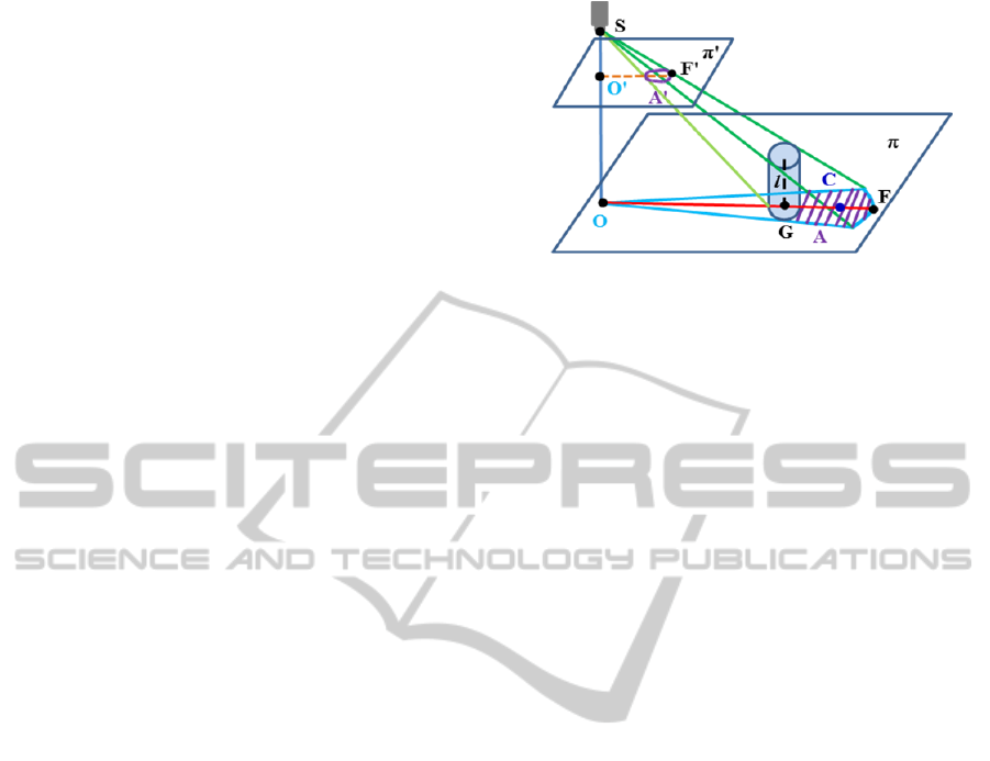
Figure 1 shows the geometric relationship when
an image of a person is taken by an overhead camera
S. A person is modeled as a cylinder with the central
vertical axis l. π is the plane perpendicularly
intersecting l at the ground point G. If the ground is
flat, π is the ground plane since the person is upright.
Otherwise π is a hypothetical plane. The optical
axisOS
is vertical with O in plane π. The perspective
projection of l lies on the lineOG
. Thus with the
assumption d), the highest head top point lies on OG
as well. And the shadow area A, the projected area
of the person on plane π, is divided into two halves
byOG
. The point C as the centroid of A should be
also on OG
which is denoted as OC
for later use. F is
the furthest point defined as
argmax
∈,∈
|
|
(1)
Figure 1: Determination of the potential head top segment.
From assumptions a) and b) we can safely argue that
a part of projected head top points lies on the
segment
no matter if the walking platform is flat.
Plane π' (in figure 1) is the image plane of camera S
and A' is the image of A, i.e. foreground blob of a
person. F' is the furthest point on the image plane,
similarly to equation (1), defined as
′ argmax
∈,∈
′′
(2)
where C' (not denoted in figure 1 because of the
limited space) is the centroid of A' and O' the image
center. So ′′
is the potential head top segment in
the image plane, with head top pixels on it.
2.2 3D Head Position Estimation
The 3D head point is the highest point of a person.
With the detected potential head top segment,
locating the 3D head point reduces to finding the
centre of points on the segment which are closest to
the cameras and thus have the largest disparity.
To calculate the disparity of each point on the
potential head top segment, its corresponding point
needs to be established from the synchronized right
image. For each pixel on the segment from left
image, we compare the RGB values of an N*N
region about the point (the template) with a series of
the same size regions extracted from the right image
(the samples). The centre of each sample, the
candidate matching point, has the same row number
as the pixel in the left image, since the left and right
camera are aligned horizontally. The pixel on the
segment is descripted as an N*N*3 vector ,
containing the RGB values of all pixels in the
template, and the candidate pixel is described as the
same size vector . The similarity of the two vectors
is evaluated by the Euclidean Distance(ED)
,
between them. A corresponding point of the point on
the potential head top segment is established if
1 ∙ 2
(3)
PedestrianTrackingbasedon3DHeadPointDetection
383
where 1 is the closest distance, 2 the second-
closest distance and the distance ratio (typically
0.8). The disparity of the point on the segment
is computed from the image coordinate difference of
the two matching pixels.
To get more accurate 3D position, we estimate
the sub-pixel disparity by considering the minimum
ED that satisfies (3) and the two neighbouring ED
values instead of just taking the point of the
minimum ED as the matching point. We fit a
parabola to the three values and analytically solve
for the minimum to get the sub-pixel correction.
The centre of the pixels with the largest rounded
disparity instead of only the pixel with largest
disparity on the potential head top segment is
determined as the head point. Thus both the disparity
and the position of the head point have sub-pixel
resolution, making the localization of the 3D head
point more robust and accurate. With the head point
in the image and its disparity (not rounded), the 3D
head position can be computed by triangulation.
3 PEDESTRIAN TRACKING
Once the 3D positions of pedestrians, denoted as the
3D head points, are obtained in each frame, they are
tracked by assuming constant moving direction and
velocity within two consecutive frames. The position
of a person is predicted at the next time interval and
a search is implemented in a neighbourhood around
the predicted point. The position of the person is
then updated by the estimated 3D head point that is
nearest to the predicted point. If no head point is
found in the search area, the person’s location is
updated using the predicted one. The person is
deleted if not found over certain extend period of
time. Similarly, if an object is not associated with
any object in the previous frame over some frame
intervals, it is regarded as a new target.
4 EXPERIMENTS
We test our approach using a publicly available
visual surveillance simulation test bed, ObjectVideo
Virtual Video. Two virtual scenes of the train station
concourse are created, one with flat ground and the
other with a small bump, whose cross section is a
trapezoid, added on the flat ground. Seven people
walk in an area of about 180*160 inches, which is an
average crowded scene: the blobs of people don’t
merge in the overhead view.
The ceiling is 348 inches high from the flat part
of the ground. Two identical synchronized cameras
are installed on the ceiling with perpendicular views.
The baseline is 40 inches. The frame rate is 15
frames per second and the frame size is 640*480
pixels. A PTZ camera is installed on the wall in both
scenes with the resolution 320*240 pixels and the
height 160 inches. We let a group of people walk on
the planar ground and then let the same group walk
on the non-planar ground using the same paths.
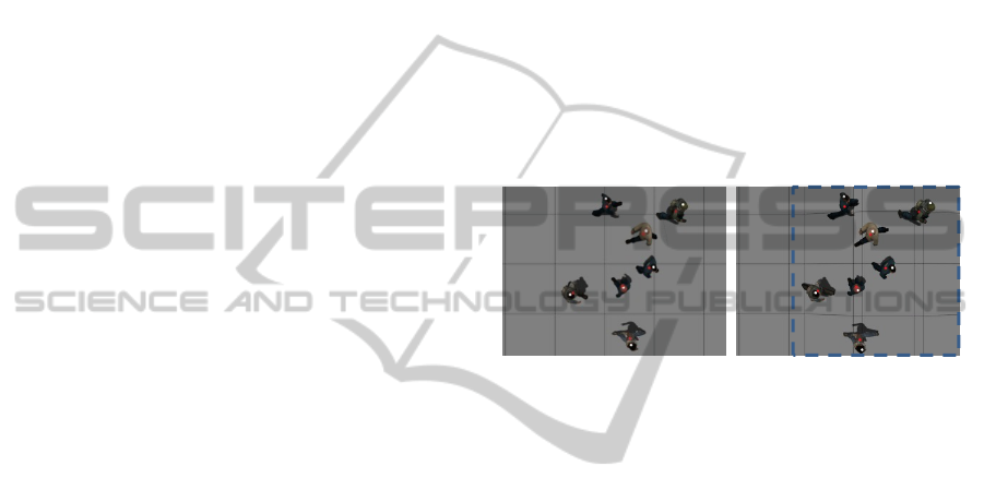
The images in figure 2 are captured by the left
camera when people walk on the planar and non-
planar ground, respectively. The foreground
centroids and the detected head points are marked as
in red and white. The detected head points are very
close to the head top centres in both scenes. The
dashed line square shows the bump area.
(a) Planar ground (b) Non-planar ground
Figure 2: The frames captured by the left camera with
people walking on the planar and non-planar ground.
The estimated 3D tracks are projected to the X-Y
plane and Z plane (height) separately. The X-Y
plane tracking results are shown in figures 3, where
the solid lines are the ground truth and the dashed
lines the estimated trajectories. The square is the
FOV centre. The number at the one end of each
trajectory denotes its object ID. The trajectories are
very close to the ground truth. Since the bump
changes people’s speeds, the tracks in the two scenes
are a little different though the same paths are set.
The Z plane tracking results are not shown
because of limit space. The errors of Z and X-Y
plane values in the two scenes are tabulated in table
1. The 3D head position errors can result from the
two reasons: a) the estimated potential head top
segment is slightly off the head top centre due to
pedestrians’ movement which makes the foreground
blob not perfectly symmetrical about the line from
image centre to blob centre; b) robust corresponding
points (in section 2.2) are not found on the head top
part of the segment or are not established correctly.
b) can cause relatively big error in both X-Y and Z
plane yet rarely happens. The ellipse in figure 3(b)
highlights the relatively big errors due to reason b).
The main errors are caused by reason a) instead and
are usually smaller than the head radius(see table 1).
VISAPP2013-InternationalConferenceonComputerVisionTheoryandApplications
384
(a) Planar ground (b) Non-planar ground
Figure 3: X-Y plane tracking results when people walking
on the planar and non-planar ground.
Table 1: The errors of the estimated tracks with planar and
non-planar ground (error unit: inch, and 1 inch=2.54 cm).
Object
ID
Planar ground Non-planar ground
X-Y
errors
Z errors
X-Y
errors
Z errors
1
1.35 1.13 1.44 1.14
2
1.87 1.48 1.47
1.43
3
1.07 1.24 0.94 1.21
4
1.70 1.70 1.64 1.46
5
1.29 1.03 2.43
2.06
6
1.88 1.02 1.90 1.53
7
1.04 1.24 1.49 1.20
With accurately estimated 3D head positions, the
PTZ camera on the wall is guided to capture close-
up facial images. Figure 4 shows the capturing
results in the scene with planar (1
st
row) and non-
planar ground (2
nd
row). The images in the first and
second row from left to right are captured when
person 5 arrives at the locations marked by the
circles in figures 3(a) and (b). The arrows show the
walking directions. Our method is very effective in
capturing close-up facial image, with almost all the
captured faces around the image centre. Even for the
point inside the ellipse in figure 3(b) where both X-
Y and Z plane errors are relatively big, the whole
face is still captured (middle image in the 2
nd
row).
Figure 4: The close-up facial images captured in the scene
with planar and non-planar ground.
5 CONCLUSIONS
We present an approach based on 3D head point
detection to track people in an average crowded
indoor environment using two overhead cameras.
Our mainly contribution is to use the perspective
projection to find the potential head top segment and
then establish the highest point on the segment to
detect the 3D head point. This makes our method
work well for accurate 3D tracking without
assuming the heights of people, without the
constraint that the ground is flat or planar, and
without using full disparity map that is
computationally expensive. Thus our method is well
suited for capturing close-up facial image. The
experiments show that the average error of the
estimated X-Y and Z plane values of the 3D head
point is usually smaller than 2 inches and high
quality close-up facial images are captured.
In the future we plan to investigate a global
matching method to obtain more accurate and robust
disparity along the potential head top segment, thus
improving on the 3D head point localization. And
we intend to extend our method to very crowded
scenes where the foreground blobs of people from
the overhead view may merge.
REFERENCES
Bellotto, N., Sommerlade, E., Benfold, B., Bibby, C.,
Reid, I., Roth, D., Fernandez, C. Gool, L. V. and
Gonzalez, J., 2009. A distributed camera system for
multi-resolution surveillance. In ACM/IEEE
International Conference on Distributed Smart
Cameras, 2009.
Boltes, M. and Seyfried, A., 2012. Collecting pedestrian
trajectories. Neurocomputing, [online] Available at<
http://dx.doi.org/10.1016/j.neucom.2012.01.036>.
Eshel, R. and Moses, Y., 2008. Homography based
multiple camera detection and tracking of people in a
dense crowd. In IEEE Conference on Computer Vision
and Pattern Recognition. Anchorage, Alaska, USA 24-
26 June, 2008, pp. 1-8.
Khan, S.M. and Shah, M., 2009. Tracking multiple
occluding people by localizing on multiple scene
planes, IEEE Transactions on Pattern Analysis and
Machine Intelligence, 31 (3), pp. 505–519.
Oosterhout, T. van, Bakkes, S. and Kröse, B., 2011. Head
detection in stereo data for people counting and
segmentation. In International Conference on
Computer Vision Theory and Applications, 2011.
Orwell, J., Massey, S., Remagnino, P., Greenhill, D. and
G. Jones, 1999. A Multi-agent framework for visual
surveillance. In IEEE International lst Conference on
Image Processing, 1999.
0 50 100 150
-240
-220
-200
-180
-160
-140
-120
-100
-80
3
5
4
7
2
6
1
0 50 100 150
-240
-220
-200
-180
-160
-140
-120
-100
-80
1
7
3
4
5
6
2
PedestrianTrackingbasedon3DHeadPointDetection
385
