
Improving Neuron Stimulation Efficency by Altering Electrode
Geometry
A. Ghazavi
1
, D. Westwick
1
, C. Luk
2
, N. I. Syed
2
and C. Dalton
1
1
Department of Electrical and Computer Engineering, University of Calgary, Calgary, Alberta, Canada
2
Department of Anatomy and Cell Biology, University of Calgary, Calgary, Alberta, Canada
Keywords: Neuron-electrode Interface, Neuron Stimulation, Sealing Resistance, Finite Element Model, Micro
Electrode Array.
Abstract: Microelectrode arrays (MEA) are non-invasive tools for recording brain cell activity and have been
successfully applied to a variety of neurons. However, MEAs fail where consistent stimulation of neurons is
desired over an extended period of time. Here, a model is presented to study features that provide optimum
stimulation threshold from different sizes and shapes of electrodes. Both simulation and in vitro
experimental results suggest that star-shaped electrodes enable a threshold voltage that is 25% lower than
that of an electrode with a circular shape, and are thus considered more efficient for neuronal stimulation.
These findings are important as they will help produce more efficient microelectrode arrays for in vivo
applications such as prosthetic devices, as well as for long-term in vitro neuron stimulation for studying
neuronal networks and function.
1 INTRODUCTION
Stimulating microelectrode arrays are the basis for
neuroprosthetic devices such as cochlear and retinal
implants, bladder prostheses, upper and lower limb
prosthetics as well as treatments for neurological
disorders such as nerve regeneration electrodes, deep
brain stimulation and vagus nerve stimulation
(Cogan, 2008). Electrodes used for neuron
stimulation should be able to stimulate the neurons
for a long time period without causing neural
damage (Rutten, 2002). Efficient power
consumption of the electrode is also an important
feature to be considered in their design (Wei and
Grill, 2009). In order to optimize the neuron
stimulation to achieve physiological levels of
stimulation, it is necessary to design a more effective
neuron-electrode junction. Several models have been
used to investigate different approaches for
improving an individual neuron-electrode interface.
Investigations have considered: the effect of
complete and defect sealing on sealing resistance
and stimulus transfer; the effect of cell size on
membrane depolarization (Buitenweg et al., 1999);
the effects of neuron eccentricity; sealing gap size,
and both cell and microelectrode radius for circular
microelectrodes smaller than the cell on passive
membrane depolarization (Buitenweg et al., 2003);
the effects of anodic and catodic current stimuli on
cell excitation for a circular microelectrode larger
than the cell (Schoen and Fromherz, 2008) and the
efficiency of high-perimeter planar electrodes for
exciting axons (Wei and Grill, 2009).
In the present research, the electric field pattern
for different planar microelectrode dimensions and
shapes was investigated, in order to optimize the
electrode geometry and to obtain the largest electric
field within a cell. Our research shows that shapes
with sharp edges and longer perimeters result in
higher electric fields and sealing resistances.
2 MATERIALS AND METHODS
2.1 Experimental Methods
Neurons were experimentally stimulated by a
microelectrode array and their responses were
measured using sharp electrodes. The lowest
stimulation amplitude which caused an action
potential was compared between the different
electrode designs.
51
Ghazavi A., Westwick D., Luk C., Syed N. and Dalton C..
Improving Neuron Stimulation Efficency by Altering Electrode Geometry.
DOI: 10.5220/0004238900510056
In Proceedings of the International Conference on Biomedical Electronics and Devices (BIODEVICES-2013), pages 51-56
ISBN: 978-989-8565-34-1
Copyright
c
2013 SCITEPRESS (Science and Technology Publications, Lda.)
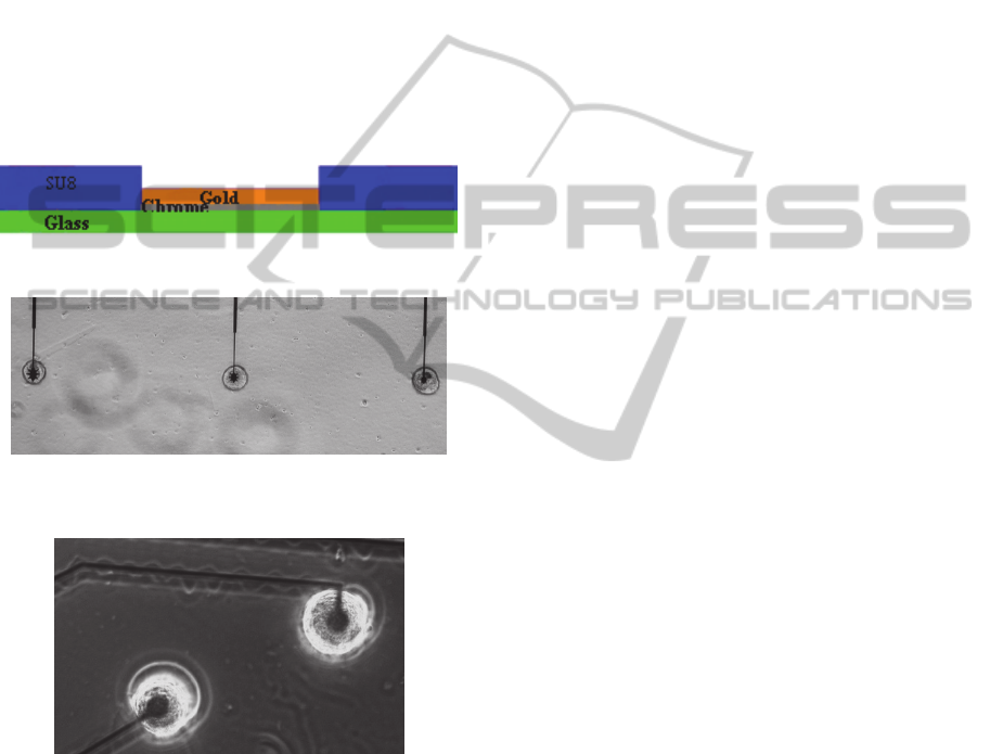
2.1.1 Planar Electrodes
Electrolyte/SU8/Au/Cr electrodes were used in this
research. Electrodes are fabricated onto 1mm glass,
with 10nm chrome and 150nm gold (Figure 1). The
electrodes are covered with 0.5µm SU-8, which is
patterned to have holes through the SU-8 to the star
electrodes. The SU-8 layer aids physical location of
the cell. The star-shaped electrodes are made in three
different sizes with areas of approximately 280
,
478
and 798
and perimeters of
approximately 106µm, 148µm and 186µm (Figure
2), respectively. On each chip, there were three star
shaped electrodes, each one with a Lymnaea
stagnalis neuron, left pedal dorsal1 (LPeD1),
cultured on it.
Figure 1: Cross section of one electrode.
Figure 2: Star electrodes with LPeD1 neurons cultured on
them. The distance between electrodes is 100µm.
Figure 3: Circular electrodes with LPeD1 neuron cultured
on them.
Conventional circular electrodes, 30µm in
diameter were used for comparison purposes (Figure
3). The area and perimeter of the circular electrodes
was 707
and 94µm, respectively. Four neurons
were cultured onto four different circular electrodes.
The electrodes were set at a distance of 100µm from
each other.
2.1.2 Neurons
Neurons were extracted from isolated Lymnaea
Stagnalis brains. The cell culture process was done
according to previously published protocols as
described by Syed et al. (1999). The cells were
cultured on the electrodes which had been coated
with poly-L-Lysine one day prior to the stimulation
experiments.
2.2 Finite Element Modelling
An individual neuron-electrode interface has been
modelled using the electric current mode of
COMSOL 4.3(COMSOL Inc, USA), a Finite
Element Modelling (FEM) software package. The
transient FEM was developed in three-dimensions to
model neuronal response in the subthreshold region.
The model was meshed with 772014 and 622573
tetrahedral mesh elements for the star and circular
electrodes, respectively. Poisson equation was
solved numerically via FEM.
. 0
(1)
V the electrical potential and σ is the medium
conductivity. The model includes an insulating
surface around the glass. A falling voltage ramp with
a slope of -60mV/ms in the duration of 10ms has
been applied to the electrode. The passive response
of neurons to subthreshold voltage ramp
stimulations was compared for different electrodes.
Since the membrane as well as the sealing gap and
electrode double layer have small thicknesses
compared to the other dimensions of the model, they
have been modelled with a thickness larger than
their actual thickness and their conductivity and
permittivity have been compensated for the
difference, as described by Buitenweg et al. (1999)
and Choie and You (2012).
The level of discretization was validated by
comparing both denser and coarser meshes.
2.2.1 Microelectrode
Several models have been proposed to represent the
electrode-electrolyte impedance. There are two
processes at the interface; faradaic and non-faradaic.
In this research it has been assumed that there is no
faradaic current at the gold-extracellular interface so
the charge-transfer resistance and Warburg
impedance have not been implemented in this
model. Capacitive charging of the electrode double
layer (DL) has been assumed to be the source of
neuron stimulation. These currents are produced by
the electrode double layer which acts as a capacitor.
The pseudo capacitive resistance is assumed to be
purely capacitive so:
BIODEVICES2013-InternationalConferenceonBiomedicalElectronicsandDevices
52

;β=1 , k=1/C
(2)
In this work, the value 15µF/
as reported in
literature, has been used for electrode impedance
(Huang et al., 2004); (Yúfera et al., 2003). In reality
the electrode DL is about 2nm (Huang et al., 2004).
Since meshing very thin layers in FEM is
computationally costly, in the model a higher
thickness 0.5µm has been considered and the
difference is implemented in the permittivity.
.
(3)
2.2.2 Neuron
The neuron was simulated as a paraboloid shape
with radius 30µm and height 20µm
(height0.7*radius). Variation of the height of
neuron has a very small effect on stimulus transfer
(Buitenweg et al., 1999). Since passive membrane
properties have been assumed in the model,
capacitive and resistive properties of the membrane
are implemented in the model. Since a membrane’s
capacitance is inversely related to its thickness,
which has a constant value for animal cells
(Molleman, 2003), we have considered the
value1µF/
, as reported in other literature (Choi
and You, 2012); (Molleman, 2003); (Huang et al.,
2004); (Moulin et al., 2008); (Elia et al., 2009);
(Buitenweg et al., 2003); (Schoen and Fromherz,
2007) for membrane specific capacitance.
The resistive properties of the membrane were
represented by its conductivity. Right Pedal Dorsal1
(RPeD1) neuron’s electrophysiology and size is
almost the same as those of Left Pedal Dorsal1
(LPeD1) neuron, so the conductivity of RPeD1,
10nS (Lu and Feng, 2011), was used. The
conductance and relative permittivity for the
intracellular medium was considered to be 1.43S/m
and 80, respectively. Due to the small thickness of
the membrane, 8 nm (Huang et al., 2004), a large
number of mesh elements was required. So it has
been modelled as an interface layer between the
intracellular and extracellular media (Choi and You,
2012).
.
(4)
.
(5)
The gap between the cell and electrode is in reality
around 50nm (Schoen and Fromherz, 2008), which
was implemented as 0.5µm in the model, and then
compensated for by using a higher conductivity.
.
(6)
A geometric visualization of a neuron sitting on top
of the star-shaped electrode, as implemented in
COMSOL, is depicted in (Figure 4).
Figure 4: 3D geometry used in finite element modelling.
2.2.3 Electrolyte Bath
The values 1.65S/m and 80 were assigned to the
conductivity and relative permittivity of the
extracellular medium. It was modelled as a 60µm
diameter hemisphere. The boundary of this area was
considered as an electrical ground representing an
electrode faraway and its potential was set to zero
potential.
3 RESULTS
3.1 Passive Response under
Current-clamp
Experiments were performed with three electrodes
of each shape and size. Since falling voltage ramps
depolarize the membrane with a lower slope than is
required by rising ramps (Schoen and Fromherz,
2008), falling voltage ramps with steps of -50mV
were used for the experiments. The cells were
stimulated by the microelectrode arrays and the
intracellular response was measured using a sharp
electrode. A circular electrode with an area of
707µ
and perimeter of 94µm caused an action
potential (AP) when the stimulus exceeded -
1000mV. The small, medium and large star shaped
electrodes with perimeters of 106µm, 148µm,
186µm and areas of about 280
, 478
and
798
all caused APs with -750mV stimuli, which
is 25% less than the circular electrode. So although
the large star shaped electrode has a larger area than
the circular electrode, it can stimulate the cells using
lower voltages.
Simulation results of intracellular response of the
star-shaped electrode versus horizontal displacement
from the centre of electrode, is depicted in (Figure
5).
ImprovingNeuronStimulationEfficencybyAlteringElectrodeGeometry
53
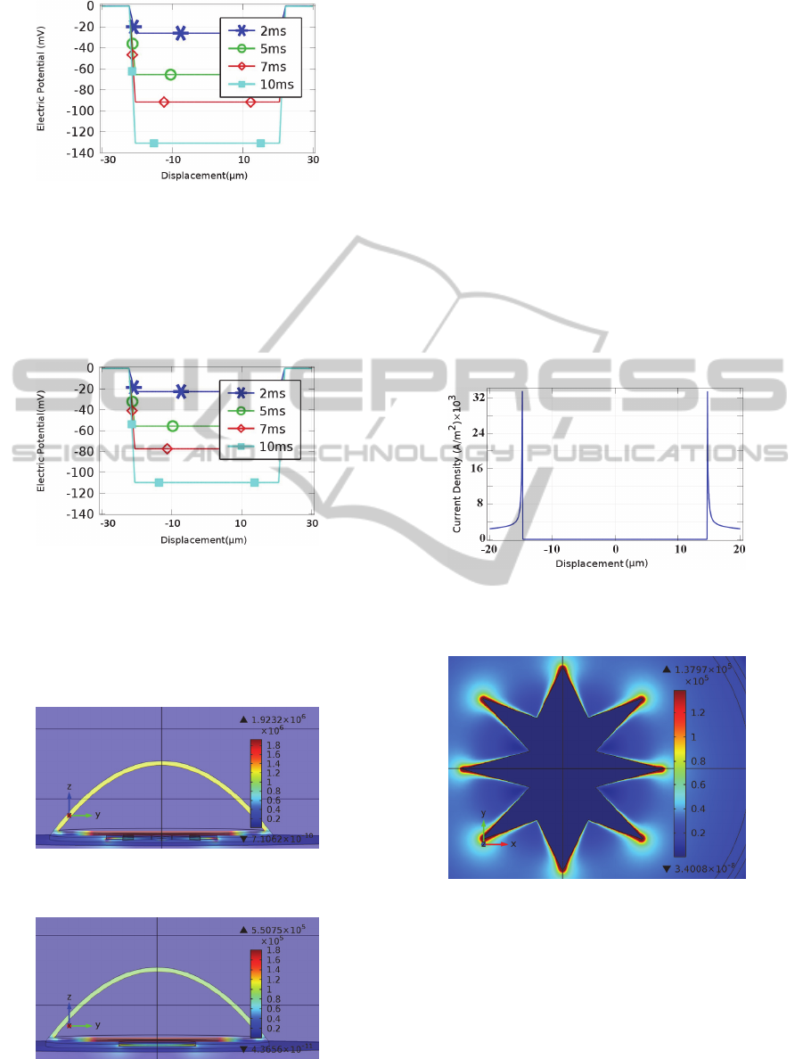
Figure 5: Intracellular Response to extracellular
stimulation with falling voltage ramp of -60mv/ms and
star electrode with respect to displacement from the
centre, at times 2ms, 5ms, 7ms and 10ms.
Simulation results of the intracellular response
due to a circular electrode with the same area as the
star-shaped electrode is illustrated in (Figure 6).
Figure 6: Intracellular response to extracellular stimulation
with falling voltage ramp of -60mv/ms and circle electrode
with respect to displacement from the centre, at times 2ms,
5ms, 7ms and 10ms.
As can be seen, the star electrode, results in a
larger hyperpolarisation of the intracellular medium.
Figure 7: Electric field at different areas of the cell at the
termination of stimulus voltage ramp on star electrode.
Figure 8: Electric field at different areas of the cell at the
termination of stimulus voltage ramp on circular electrode.
Figures 7 and 8 show that the electric field is
larger in the unattached membrane for the star-
shaped electrode in comparison to the round
electrode.
3.2 Current Density Distribution on
Electrode
It has been reported that high charge density on the
electrode surface can result in cell damage when
these electrodes are used for stimulating parts of
brain tissue (McCreery et al., 1990). With the
experiments performed here it was observed that
using star shaped electrodes did not cause cell death
or visibly damage the individual cells. Figures 9 and
10 illustrate the current density distribution on the
star-shaped electrode surface at the termination of a
stimulus.
Figure 9: Current density on star electrode due to -
60mV/ms falling voltage ramp stimuli, versus
displacement from the centre of electrode at t=10ms.
Figure 10: Current density distribution on star electrode
due to -60mV/ms falling voltage ramp stimuli at t=10ms.
Figures 11 and 12 illustrate the current density
distribution on the circular electrode surface at the
termination of a stimulus.
As seen in figures 9 and 11, the star electrode
results in a spatial non-uniformity in the current
density which is almost three times that of the
circular electrode. Since the activating function is
proportional to the spatial derivative of current
BIODEVICES2013-InternationalConferenceonBiomedicalElectronicsandDevices
54
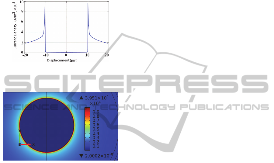
density, larger non-uniformity results in a larger
activating function and thus more effective
stimulation (Wei and Grill, 2009). Furthermore,
during the experiment no cell damage was observed
and the threshold voltage was reduced for the star
electrodes, as compared to the circular electrode.
Figure 11: Current density on circular electrode due to -
60mV/ms falling voltage ramp stimuli, versus
displacement from the centre of electrode at t=10ms.
Figure 12: Current density distribution on circular
electrode due to -60mV/ms falling voltage ramp stimuli at
t=10ms.
The sealing resistance obtained from FEM
ANALYSIS was calculated by dividing the
electrode voltage by the whole current on the
electrode surface while assuming that current
through the cell is negligible compared to current
through the sealing gap (Buitenweg et al., 1999).
The sealing resistance of the star electrode at 9ms
was 5GΩ while for the circular electrode it was
32.9MΩ. This shows that sealing resistance
increases by changing the electrodes shape from
circular to star.
3.3 Model Validation
The simulation results were compared with
experimental data using custom made MEAs with
various electrode geometries. The results of FEM
ANALYSIS matched well with the experimental
results. Since experimentally star-shaped electrodes
were excited at lower voltages compared to round
electrodes.
The experimental results showed that an action
potential was triggered by smaller stimulus
amplitudes when star shaped electrodes were used
instead of circular electrodes. Previous studies
(Buitenweg et al., 2003) show that smaller circular
electrodes result in higher intracellular response. The
electrode areas of two star shaped electrodes are
smaller than the circular electrode and they resulted
in a cell excitation with lower stimulus. However the
larger star electrode which had a larger area than the
circular electrode caused neuron excitation with
lower stimulus amplitudes as well.
4 CONCLUSIONS
Circular microelectrodes with smaller radius
produce a larger response to extracellular
stimulation (Buitenweg et al., 2003). Serpentine
electrodes in centimetre dimensions reduced the
threshold voltage at higher perimeters and farther
distances from the electrode (Wei and Grill, 2009).
In the present study we examined the effect of sharp
edges as well as perimeter and area on neuron
stimulation by microelectrodes. Results show that
sharp edges have a higher impact than other
geometries since the medium and large star
electrodes were excited by the same voltage. The
model result showed that using electrodes with the
same area but different perimeter and sharp edges
results in larger hyperpolarisation in the cell and a
higher current density, almost three times that of the
round electrode, at the edges. Therefore, it would be
ideal if electrodes were designed to be smaller than
the neuron being investigated and also to contain
sharp edges. Future work will investigate different
electrode geometries, both through simulation and
also via experimental study.
ACKNOWLEDGEMENTS
The authors wish to acknowledge the research grants
from the Alberta Ingenuity Fund, The Natural
Sciences and Engineering Research Council of
Canada (NSERC) and The Canadian Institute of
Health Research (CIHR), Regenerative Medicine
and Nanomedicine Program RMF 82496.
We also wish to thank the Advanced
Micro/Nanosystems Integration Facility at the
University of Calgary for fabricating the devices.
ImprovingNeuronStimulationEfficencybyAlteringElectrodeGeometry
55

REFERENCES
Buitenweg, J. R., Rutten, W. L. C. and Marani, E., 1999.
‘Finite element modeling of the neuron-electrode
interface’, IEEE Engineering in Medicine and Biology
Magazine, vol.19, no.6, pp. 46-52.
Buitenweg, J. R., Rutten, W. L. C., Marani, E., 2003.
‘Geometry-based finite-element modeling of the
electrical contact between a cultured neuron and a
microelectrode’, Biomedical Engineering, IEEE
Transactions on, vol.50, no.4, pp.501-509.
Choi, C. T. M., You, S., 2012. ‘Finite element models of
neuron electrode sealing interfaces’, Magnetics, IEEE
Transactions on, vol.48, no.2, pp.643-646.
Cogan S. F., 2008. ‘Neural stimulation and recording
electrodes’, Ann. Rev. Biomed. Eng, vol.10, pp.275-
309.
Elia S., Lamberti P., Tucci V., 2009. ‘A finite element
model for the axon of nervous cells’, COMSOL
Conference.
Huang, X., Nguyen, D., Greve, D. W., Domach, M. M.,
2004. ‘Simulation of microelectrode impedance
changes due to cell growth’, Sensors Journal, IEEE,
vol.4, no.5, pp. 576- 583.
Lu T. Z., Feng Z-P, 2011. ‘A sodium leak current
regulates pacemaker activity of adult central pattern
generator neurons in Lymnaea Stagnalis’. PLoS ONE,
vol.6, no.4, p.e18745.
McCreery, D. B., Agnew, W. F., Yuen, T. G., Bullara, L.,
1990. ‘Charge density and charge per phase as
cofactors in neural injury induced by electrical
stimulation’. IEEE Trans. Biomed. Eng., vol.37, no.10,
pp.996–1001.
Molleman A., 2003. ‘Basic Theoretical Principles, in
Patch Clamping: An Introductory Guide To Patch
Clamp Electrophysiology’, John Wiley & Sons, Ltd,
Chichester, UK.ch2.
Moulin C., Gliere A., Barbier D., Joucla S., Yvert B.,
Mailley P., Guillemaud R., 2008. ’A new 3-D finite-
element model based on thin-film approximation for
microelectrode array recording of extracellular action
potential’ IEEE Trans. Biomed. Eng., Vol.55, pp.683-
92.
Rutten, W. L. C. 2002. Annu. Rev. Biomed. Eng. 4, 407.
Schoen I, Fromherz P., 2007. ‘The mechanism of
extracellular stimulation of nerve cells on an
electrolyte-oxide-semiconductor capacitor’. Biophys.
J., 92, vol.92, no.3, pp.1096–1111.
Schoen, I., Fromherz, P., 2008. ‘Extracellular stimulation
of mammalian neurons through repetitive activation of
Na+ channels by weak capacitive currents on a silicon
chip’. J Neurophysiol, vol.100, no.1, pp.346–357
Syed, N. I., Zaidi, H., Lovell, P., 1999. U. Windhorst, H.
Johansson (Eds.),’ Modern Techniques in
Neuroscience Research’, Springer, Berlin, Heidelberg
, pp. 361–377.
Wei X. F., Grill W. M., 2009. ‘Analysis of high-perimeter
planar electrodes for efficient neural stimulation’.
Front. Neuroeng. , vol.2, no.15.
Yúfera, A., Olmo, Daza, P and Cañete, D. A., 2003. ‘Basic
Theoretical Principles, in Patch Clamping: An
Introductory Guide To Patch Clamp
Electrophysiology’, John Wiley & Sons, Ltd,
Chichester, UK. ch2.
BIODEVICES2013-InternationalConferenceonBiomedicalElectronicsandDevices
56
