
BITtalino: A Biosignal Acquisition System based on the Arduino
Ana Priscila Alves
1
, Hugo Silva
1
, Andr
´
e Lourenc¸o
1,2
and Ana Fred
1
1
Instituto de Telecomunicac¸
˜
oes, Instituto Superior T
´
ecnico, Avenida Rovisco Pais, 1, 1049-001 Lisboa, Portugal
2
Instituto Superior de Engenharia de Lisboa, Rua Conselheiro Em
´
ıdio Navarro, 1, 1959-007 Lisboa, Portugal
Keywords:
Biomedical Instrumentation, Arduino, Signal Acquisition, ECG, Biometrics.
Abstract:
Our work presents a low-cost biosignal acquisition system, BITalino, based on the Arduino hardware platform;
both the hardware and software components are detailed, together with experimental evaluation. This system
was designed to be integrated in a biometric platform based on Electrocardiographic (ECG) signals, that will
be used for identity recognition. The experimental evaluation revealed that this system is not only capable
of ECG signal acquisition, for biometric purposes, but it can also be used as a generic platform for other
biomedical applications, greatly extending its applicability. In this paper we describe the proposed platform,
with special emphasis on the design principles and functionality. Future work will focus on further developing
our hardware, targeting its integration in a prototype system for ECG-based biometric recognition.
1 INTRODUCTION
Biosignal acquisition has been a topic of increas-
ingly growing development, since it constitutes the
basis for diagnostic systems, and contributes to a bet-
ter understanding of the body functions. Nowadays,
novel applications of biosignals are emerging in areas
where they are not traditionally found, such as the use
of Electrocardiographic (ECG) signals for biometric
purposes (Biel et al., 2001) (Lourenc¸o et al., 2011).
Therefore, the main objective of our work was to de-
velop a low-cost acquisition system, capable of cap-
turing vital signs, using the ECG as a testbed.
There are multiple hardware choices available,
however the Arduino is currently the most flexible and
easy-to-use hardware and embedded software plat-
form, with low cost, easy communication, and soft-
ware running on a computer or other devices. Our
goal was to integrate the Arduino board with the An-
droid Operating System, targeting the development of
a mobile biometric system; as such, the chosen com-
munication protocol was Bluetooth, since it is avail-
able in almost every mobile device, and also in com-
puters. The integration between Arduino and Android
is not new (Google ADK, 2011), but very few initia-
tives are based on Bluetooth.
The first use of our acquisition system targets the
integration in a biometric platform, allowing real-time
recognition. However, it can be extended to numerous
other important applications, depending on which sig-
nals are to be acquired.
Nowadays, the use of the Arduino in medical and
health applications has been widely explored for sim-
ple usage scenarios. One particular example is avail-
able at (Medicarduino, 2012), where the Arduino is
used to acquire EEG signals, measure pulse, detect
alcohol levels, and many other examples. Therefore,
this project will contribute to the creation of a new
system, modular, multi-purpose, easily accessible and
with the possibility to be assembled by anyone inter-
ested on biosignal acquisition.
In the following sections we describe the acquisi-
tion system, designed especially for ECG data collec-
tion. The document is organized as follows: Section 2
focuses on the global system architecture, and in Sec-
tion 3, 4 and 5 the hardware, firmware and software
are detailed; Section 6 presents experimental results
obtained with this system. Finally, Section 7 outlines
the main conclusions and future work.
2 SYSTEM ARCHITECTURE
The proposed acquisition system has two main parts:
Hardware and Software. In this particular work, the
hardware is composed by the Arduino platform, Blue-
tooth transceiver and ECG sensor.
In the case of ECG acquisition, the electrical activ-
ity of the heart is captured using electrodes placed on
two fingers of opposed hands. Those signals are ac-
261
Alves A., Silva H., Lourenço A. and Fred A..
BITtalino: A Biosignal Acquisition System based on the Arduino.
DOI: 10.5220/0004243502610264
In Proceedings of the International Conference on Biomedical Electronics and Devices (BIODEVICES-2013), pages 261-264
ISBN: 978-989-8565-34-1
Copyright
c
2013 SCITEPRESS (Science and Technology Publications, Lda.)
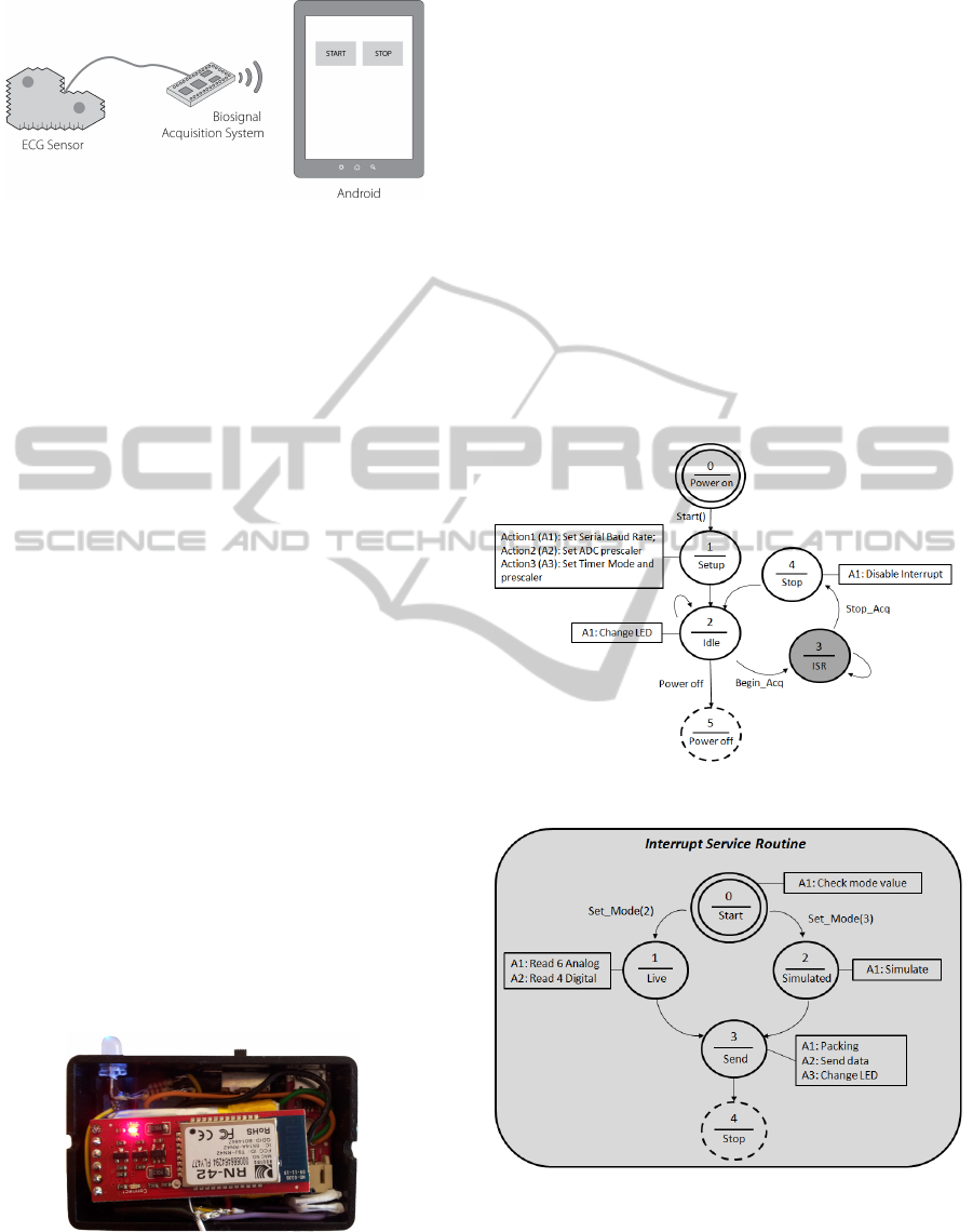
Figure 1: Diagram of the Android Biometric Platform.
quired through the analog input ports on the Arduino
board, and subsequently converted using the internal
analog-to-digital converter. Then, the digitalized data
is sent via Bluetooth to the base station (e.g. Android
mobile phone). The diagram represented in Figure 1
synthesizes the overall architecture of the hardware
subsystem, showing a schematic of the main compo-
nents.
Regarding the software, there are two main pro-
grams developed: the Arduino Firmware, which con-
trols its operation, and an Application Programming
Interface (API) in Java, which communicates with the
Arduino, controls the acquisition process, allows the
access to the collected raw data and enables high-level
applications to access both the device and the data.
These two parts of the system will be detailed in the
next sections.
3 HARDWARE
The main component of this section is the Arduino.
Figure 2 shows the final prototype, with main com-
ponents: one Arduino Pro Mini (3.3V and 8MHz),
directly connected to a Bluetooth Mate module; and
one Lithium Ion Polymer battery with nominal volt-
age of 3.7V at 400mAh, as power supply. The ECG
sensors are connected to one of the BITalino analog
input pins, and its specifications are detailed in (Silva
et al., 2011).
Figure 2: BITalino prototype.
4 FIRMWARE
The firmware development performed in our work
was designed to define the behavior of the Arduino
microcontroller, setting its parameters, such as sam-
pling rate, baud rate and communication protocol. In
this section we will describe the major objectives,
problems encountered, and solutions achieved.
The main purpose of the firmware is to control
the analog and digital acquisition, using a pre-defined
sampling rate; all the data acquired is sent to another
device via Bluetooth or USB connection. The open-
source Arduino environment makes it easy to write
code and upload it to the I/O board, which is one of
the main reasons why this platform was chosen as the
base for our system. The global operation is repre-
sented in Figures 3 and 4.
Figure 3: State diagram of the firmware operation.
Figure 4: State diagram of the ISR operation.
There are three modes in which the Arduino can
be operating:
a) Live: In this mode, the system continuously sam-
ples the physical analog and digital channels,
packs all the data, and sends it through the UART.
BIODEVICES2013-InternationalConferenceonBiomedicalElectronicsandDevices
262

All these tasks should be concluded within a time
frame, which is imposed by the sampling rate.
b) Simulated: Although it is similar to what happens
in acquisition mode, in this mode, the system will
simulate the acquisition, transmitting synthesized
signals. These correspond to sinusoidal, square
and sawtooth waves. This way, the communica-
tion and interaction between the base station and
the device can be tested.
c) Idle: The system disables any mode in which it is
in, and stays in stand-by until it receives a com-
mand to start the Live or Simulated modes.
When in Live mode, 2 analog and 4 digital in-
put pins are read, and their data saved in an array.
In order to make the most efficient of the available
bandwidth on the communication channel, those val-
ues are packed into 4 bytes, including also a sequence
number, and a 4-bit Cyclic Redundancy Check (CRC)
value to detect possible errors in the message. This
packing process is done using bitwise operators, and
its schematic can be seen in Figure 5.
(a) Unpacked. (b) Packed.
Figure 5: Data packets schematic.
After concluding this step, all data is sent to the
computer through the UART.
One important requirement of this system is the
accuracy in the sampling rate. In the live and simu-
lated mode, all the tasks are completed inside a func-
tion called at a specified frequency. The approach
used was based on timer interrupts.
An interrupt is an external event that stops the run-
ning program to execute a special interrupt service
routine (ISR). After completing the ISR, the running
program is resumed to execute the next instruction.
These interruptions can occur at a specific frequency,
when associated with timers.
The Arduino Pro Mini has a clock speed of 16
MHz and 3 timers: Timer 0 (8 bits), Timer 1 (16 bits)
and Timer 2 (16 bits).It can be configured in 16 oper-
ation modes. In this work, we used the Clear Timer
on Compare match (CTC) mode, based on compari-
son, that is, the timer compares a counter value with
an output compare register defined by the user, and
every time they match, an interruption occurs and the
ISR function is called.
5 SOFTWARE
An Application Programming Interface (API) was de-
veloped in Java in order to control the Arduino. Its
main purpose is to establish Bluetooth connection,
and then start or stop the acquisition, receiving the
acquired samples, and configuring the device.
An abstract class Device was created, which was
subdivided into 2 main subclasses: Bluetooth and
Test.
a) Bluetooth: This subclass establishes a Bluetoothl
connection with the Arduino, and control its oper-
ation sending commands that activate start or stop
methods. When start is activated, all data received
from the device is saved in a text file for further
processing.
b) Test: The Test subclass does not communicate
with the device, but is used to test the API func-
tionality.
The configuration parameters used in these sub-
classes, such as baud and sampling rates, are speci-
fied in a document with a standard notation based on
JSON (JavaScript Object Notation). It creates an easy,
standard, Human-readable and structured way to rep-
resent diverse information, and works regardless of
the adopted programming language. An example of
setup parameters defined using the JSON notation is
as follows:
{ "BaudRate":115200,"Mode":"Live",
"Sampling Rate":1000}
Focusing on the particular operations that can be
performed using the Bluetooth subclass, the main
methods are:
1. Setup: A JSON Object containing information
about Sampling Rate, Acquisition mode (Live or
Simulated), and Baud Rate is parsed and, with
this information, a Bluetooth connection is estab-
lished.
2. Start: The mode number corresponding to start
acquisition, Live or Simulated, is sent to the sys-
tem, which will activate its acquisition state.
3. Acquire: After activating the acquisition state,
this method reads the incoming data, and saves
each sample in a text file, using the test applica-
tion described in the next subsection.
4. Stop: When this method is called, the acquisition
state is stopped, and the system returns to the idle
state.
To test the API functionality and benchmark the de-
vice, a test application was developed; it creates an
BITtalino:ABiosignalAcquisitionSystembasedontheArduino
263

applet with Start and Stop buttons, and calls the corre-
sponding methods. Thus, when the application starts,
the Bluetooth communication is established, and it re-
mains waiting for a button to be pressed, executing the
method Start and Acquire when the button “start”
is pressed, and calling Stop method when the button
“stop” is pressed.
6 EXPERIMENTAL EVALUATION
Tests were performed to the final system, to check
the sampling rate and the quality of ECG signals ac-
quired. Therefore, to verify if the Arduino was ac-
quiring at the specified sampling rate of 1000 Hz, a
synthesized square wave with a frequency of 10KHz,
duty cycle of 50%, 4 V
pp
and offset of V
cc
/2 was
acquired, and the data was analysed using Matlab.
The signals were generated using an Agilent 33220A
function generator. The synthesized wave revealed
a square wave, as expected, but after measuring the
number of samples in each pulse we verified an av-
erage loss of 5 samples per second. However, since
our main purpose is to acquire ECG signals, and its
bandwidth is approximately 100Hz, a much lower
sampling rate of 200Hz can be used for data acqui-
sition, leading to a maximum loss of 1 sample per
second, which is negligible for biometric recognition
purposes.
(a) Raw Waveform. (b) Filtered Waveform.
Figure 6: ECG signal acquisition.
This behaviour was already expected due to the
Arduino’s clock accuracy error of 0.2%. However,
there are some possible solutions to overcome this
problem, which will be a part of future work, and de-
scribed in section 7.
In what concerns the ECG signals, the acquisition
was performed using 2 finger electrodes on opposed
hands, with a sampling rate of 1KHz. In Figure 6
the raw 6(a) and filtered 6(b) signals are represented.
The filtering was done with a low-pass kaiser filter be-
tween 2.5 and 30 Hz. Therefore, it was concluded that
this system is able to acquire these signals with qual-
ity, being possible to distinguish the different com-
plexes of a characteristic ECG signal, when filtered.
Moreover, the battery lifetime was tested, and it oper-
ates, on average, 6 hours in constant acquisition.
7 CONCLUSIONS AND FUTURE
WORK
We have designed and implemented a first prototype
of an ECG acquisition system, applicable to biomet-
ric applications. Experimental results have shown that
the data collected through the proposed system, pre-
serves the waveform properties that are used by the
ECG-biometric systems. Although this system was
designed to integrate a biometric platform, it can also
be used to acquire other types of biosignals, becoming
a more generic acquisition system.
Future work will be focused on the integration of
an external oscillator in the system, separating the ex-
ecution lines for data acquisition and the data trans-
mission, and increasing the resolution of the system,
through an external ADC. However, in it’s current
state, this prototype system is already prepared for de-
ployment in real-world test beds, and is an adequate
low-cost alternative for large-scale data acquisition.
ACKNOWLEDGEMENTS
This work was funded by the Fundac¸
˜
ao para a
Ci
ˆ
encia e Tecnologia (FCT) under grants PTDC/EIA-
CCO/103230/2008, SFRH/BD/65248/2009 and
SFRH /PROTEC/49512/2009 whose support the
authors gratefully acknowledge. The authors would
also like to thank the Institute for Systems and
Technologies of Information, Control and Communi-
cation (INSTICC), the graphic designer Andr
´
e Lista,
Prof. Pedro Oliveira, and the Instituto Superior de
Educac¸
˜
ao e Ci
ˆ
encias (ISEC), for their support to this
work.
REFERENCES
Biel, L., Petterson, O., Phillipson, L., and Wide, P. (2001).
ECG analysis: A new approach in human identifica-
tion. IEEE Transactions on Instrumentation and Mea-
surement, 50(3):808–812.
Google ADK (2011). Accessory development kit.
http://developer.android.com/tools/adk/adk2.html.
Lourenc¸o, A., Silva, H., and Fred, A. (2011). Unveiling
the biometric potential of Finger-Based ECG signals.
Computational Intelligence and Neuroscience.
Medicarduino (2012). Medical and health related projects
with arduino. http://medicarduino.net/.
Silva, H., Lourenco, A., Lourenco, R., Leite, P., Coutinho,
D., and Fred, A. (2011). Study and evaluation of a sin-
gle differential sensor design based on electro-textile
electrodes for ecg biometrics applications. In Sensors,
2011 IEEE, pages 1764 –1767.
BIODEVICES2013-InternationalConferenceonBiomedicalElectronicsandDevices
264
